EP0802084A1 - Transmission unit - Google Patents
Transmission unit Download PDFInfo
- Publication number
- EP0802084A1 EP0802084A1 EP97104374A EP97104374A EP0802084A1 EP 0802084 A1 EP0802084 A1 EP 0802084A1 EP 97104374 A EP97104374 A EP 97104374A EP 97104374 A EP97104374 A EP 97104374A EP 0802084 A1 EP0802084 A1 EP 0802084A1
- Authority
- EP
- European Patent Office
- Prior art keywords
- friction
- output
- section
- gear
- axis
- Prior art date
- Legal status (The legal status is an assumption and is not a legal conclusion. Google has not performed a legal analysis and makes no representation as to the accuracy of the status listed.)
- Withdrawn
Links
Images

Classifications
-
- B—PERFORMING OPERATIONS; TRANSPORTING
- B60—VEHICLES IN GENERAL
- B60R—VEHICLES, VEHICLE FITTINGS, OR VEHICLE PARTS, NOT OTHERWISE PROVIDED FOR
- B60R1/00—Optical viewing arrangements; Real-time viewing arrangements for drivers or passengers using optical image capturing systems, e.g. cameras or video systems specially adapted for use in or on vehicles
- B60R1/02—Rear-view mirror arrangements
- B60R1/06—Rear-view mirror arrangements mounted on vehicle exterior
- B60R1/062—Rear-view mirror arrangements mounted on vehicle exterior with remote control for adjusting position
- B60R1/07—Rear-view mirror arrangements mounted on vehicle exterior with remote control for adjusting position by electrically powered actuators
- B60R1/074—Rear-view mirror arrangements mounted on vehicle exterior with remote control for adjusting position by electrically powered actuators for retracting the mirror arrangements to a non-use position alongside the vehicle
-
- F—MECHANICAL ENGINEERING; LIGHTING; HEATING; WEAPONS; BLASTING
- F16—ENGINEERING ELEMENTS AND UNITS; GENERAL MEASURES FOR PRODUCING AND MAINTAINING EFFECTIVE FUNCTIONING OF MACHINES OR INSTALLATIONS; THERMAL INSULATION IN GENERAL
- F16D—COUPLINGS FOR TRANSMITTING ROTATION; CLUTCHES; BRAKES
- F16D7/00—Slip couplings, e.g. slipping on overload, for absorbing shock
- F16D7/02—Slip couplings, e.g. slipping on overload, for absorbing shock of the friction type
- F16D7/024—Slip couplings, e.g. slipping on overload, for absorbing shock of the friction type with axially applied torque limiting friction surfaces
- F16D7/028—Slip couplings, e.g. slipping on overload, for absorbing shock of the friction type with axially applied torque limiting friction surfaces with conical friction surfaces
-
- H—ELECTRICITY
- H02—GENERATION; CONVERSION OR DISTRIBUTION OF ELECTRIC POWER
- H02K—DYNAMO-ELECTRIC MACHINES
- H02K7/00—Arrangements for handling mechanical energy structurally associated with dynamo-electric machines, e.g. structural association with mechanical driving motors or auxiliary dynamo-electric machines
- H02K7/10—Structural association with clutches, brakes, gears, pulleys or mechanical starters
Definitions
- the invention relates to a gear unit according to the preamble of claim 1.
- an electric motor and a multi-stage reduction gear are provided in a housing.
- the slipping clutch formed by a plurality of disks in the manner of a disk clutch is arranged between an output section of the reduction gear and an output part designed as an output pivoting part.
- the disks are compressed by a helical compression spring which is supported on the one hand on the disks and on the other hand against a head of a screw which is screwed into the output section.
- Motor-gear units of this type are used to drive exterior mirrors of motor vehicles and, in particular, of trucks.
- the slip clutch is required in each case so that the part coupled to the output part, for example a motor vehicle mirror, can also be adjusted by hand.
- the reduction gears are self-locking.
- the invention is therefore based on the object of creating a transmission unit of the generic type which consists of a few components, is easy to assemble and has a slip torque which can be specified very precisely.
- the measures according to the invention ensure that there is a very precisely definable frictional torque on the frustoconical friction surfaces, so that in turn there is also a very precisely defined slip torque, i.e. the torque at which the slip clutch slips is essentially constant within small tolerance ranges.
- the motor-gear unit shown in the drawing has a housing which consists of a lower housing part 1 and an upper housing part 2 and is made of a weldable thermoplastic, the two housing parts being provided with flanges 3, 4 which can be put together.
- the flange 3 facing the lower housing part 1 is provided with centering holes 5, while pins 6 assigned to these centering holes 5 are formed on the flange 4 of the upper housing part 2, which are inserted into the centering holes 5 and welded after assembly and assembly of the lower housing part 1 and the upper housing part 2 are, so that they also serve for the firm connection of the lower housing part 1 and upper housing part 2.
- the housing 1, 2 is provided with a receiving space 7 for an electric motor 8, the electrical supply lines 9 of which are led through an opening 10 into the receiving space 7.
- the motor 8 is reversible in the direction of rotation, that is to say it can be driven in both possible directions of rotation.
- the electric motor 8 lies in the receiving space 7 against stops 11 formed in the housing, and is therefore already aligned in its position when it is inserted into the lower housing part 1.
- the electric motor 8 is provided with a shaft 12 projecting freely from the housing 1, 2, the free end 13 of which is removed from the electric motor 8 is supported in a bearing shell 14 formed in the lower housing part 1.
- a plastic cylindrical worm 15 of a worm gear 16 is mounted such that it cannot be rotated relative to the shaft 12, for example by a press fit.
- the helical toothing 17 of the worm 15 engages in a correspondingly adapted toothing 18 of a worm wheel 19, which together with the worm 15 forms the worm gear 16.
- a planetary gear 20 is arranged downstream of the worm gear 16.
- the planetary gear 20 has a sun gear 21 which is formed in one piece with the worm gear 19 and is connected to it in a rotationally fixed manner, in whose external toothing 22 three planet gears 23, only one of which is shown, engage with their corresponding external toothing 24.
- the planet gears 23 are supported on a ring gear 25, which is provided with an internal toothing 26 in which the respective external toothing 24 of the planet gears 23 engages.
- the ring gear 25 is non-rotatable relative to the housing 1, 2, for which purpose it is provided with projections 27 on its outer circumference, which engage in adapted recesses 28 in the housing 1, 2.
- the planet gears 23 are rotatably mounted on bearing journals 29 of a web lower part 30 and are thereby held at equal angular distances from one another.
- the planet gears 23 are each formed in one piece with a gear 32 of a ring gear 33.
- the external teeth of these gears 32 of the ring gear 33 engage in an internal toothing 35 of an output ring gear 36 of the ring gear 33.
- a bearing journal 37 of an upper web part 38 engages in each of the gear wheels 32.
- the lower part 30 of the web and the upper part 38 of the web are connected to one another by means of receiving openings 39 formed on the lower part 30 of the web and connecting pins 40 engaging in them, formed on the upper part 38 of the web, to form a housing-like web.
- the output ring gear 36 has a cylindrical bearing section 41 formed in one piece with it, which is mounted radially to the common axis of rotation 42 of the worm wheel 19, the planetary gear 20 and the ring gear 33 in a bearing shell 43 which is formed on the upper housing part 3.
- the output ring gear 36 is further fixed in the direction of the axis of rotation 42 relative to the upper housing part 2 by stop surfaces 44, 45 which extend radially to the axis of rotation 42 and which prevent the rotation of the Output ring gear 36 does not hinder, but limit the play, ie the displaceability of the ring gear 36 in the direction of the axis of rotation 42 to about 0.1 mm.
- the worm gear 16, the planetary gear 20 and the ring gear 33 form a reduction gear.
- the worm wheel 19 is mounted on a continuous cylindrical axis 46 made of steel, one end of which is held in a receptacle 47 in the lower housing part 1 with a press fit, that is to say non-rotatable relative to the lower housing part 1.
- the other end of the axis 46 is supported largely without play in a cylindrical recess 48 of the output ring gear 36 which is concentric with the axis of rotation 42 radially to the axis of rotation 42, but the non-rotatable axis 46 does not hinder the rotation of the output ring gear 46.
- the worm wheel 19 is freely rotatable on the axis 46 and is supported in the direction of the axis of rotation 42 against the end face 49 of the receptacle 47 in the direction of the lower housing part 1. In the direction of the output ring gear 36, it is axially supported on the ring gear 25 of the planetary gear 20.
- the output ring gear 36 which is made entirely of metal, for example cast zinc, has an essentially cylindrical output section 50 which adjoins the bearing section 41 and which has at least one, but preferably two longitudinal grooves running diametrically opposite to the axis of rotation 42 and parallel to the axis of rotation 42 51 has.
- a friction ring 52 of a slip clutch 53 Arranged on the output section 50 is a friction ring 52 of a slip clutch 53, which engages with a protrusion 54 in each of the longitudinal grooves 51, as a result of which a rotationally fixed connection between the output ring gear 36 and the friction ring 52 is produced.
- the friction ring 52 lies against an annular collar 55 at the transition from the bearing section 41 to the driven section 51 in the direction of the axis of rotation 42. It forms the abutment surface 45 already mentioned above.
- the output section 50 is surrounded by an output pivoting part 56 which has a recess 57 running parallel to the axis of rotation 42, into which a bolt (not shown) of a part to be pivoted can engage.
- the output pivoting part 56 has a friction surface 58 which bears on a friction surface 59 of the friction ring 52. Both friction surfaces 58, 59 are frustoconical and taper away from the upper housing part 2 at a half cone opening angle a. 7 ° ⁇ a ⁇ 15 ° and preferably a ⁇ 10 °.
- the output pivoting part 56 is pressed in the direction of the friction ring 52 by means of a prestressed helical compression spring 60, only the friction surfaces 58, 59 of the pivoting part 56 and the friction ring 52 abutting one another.
- the above-mentioned slip clutch 53 is thus formed, the slip moment of which is caused by the friction coefficient between the friction surface 59 of the friction ring 52 and the friction surface 58 of the swivel part 56 and by the force, which is normal - that is, perpendicular - to the friction surfaces 58, 59 the average diameter d of the friction surface 58, 59 is determined.
- the force acting perpendicular to them between the friction surfaces 58, 59 is greater for a given force of the compression spring 60 in the direction of the axis of rotation 42, the smaller the half cone opening angle ⁇ of the friction surfaces 58, 59.
- the force acting perpendicularly to the friction surfaces 58, 59 between them is in any case several times greater, that is to say the force of the compression spring 60.
- the friction ring 52 is made of metal, for example of cast zinc, while the Output swivel part 56 consists of a common plastic.
- the helical compression spring 60 bears against the output swivel part 56 with the interposition of an annular disk serving as a pressure disk 61.
- This thrust washer 61 is also fixed in the longitudinal grooves 51 by means of projections 54 to the output ring gear 36.
- the frictional torque acting between the thrust washer 61 and the swivel part 56 is smaller than the slip torque of the slip clutch 53 by at least the quotient 10.
- the compression spring 60 also lies in the region of the free end 64 of the output section 50 against another ring disk serving as an abutment 62, which is connected to the output section 50 by means of a bayonet catch 63 is locked.
- the two washers are made of metal, for example steel. They are of identical design and have projections 54 which are adapted to the longitudinal grooves 51 and which are identical in cross section to the projections 54 on the friction ring 52.
- a partial circumferential groove 65 is formed on the output section 50 thereof, which has a longitudinal groove on one side 51 leads out.
- Each partial circumferential groove 65 is thus open at one end 66 to form a longitudinal groove 51. In contrast, it is closed at the other end 67 to the other longitudinal groove 51.
- Each partial circumferential groove 65 has a recess 68 directed towards the free end 64, which corresponds to the projections 54 on the abutment ring disk 62.
- All gearwheels with the exception of the output ring gear 36, are made of plastic and can be rotated about the axis of rotation 42 or an axis parallel thereto.
- the assembly takes place in such a way that the electric motor 8 is inserted into the receiving space 7 in the lower housing part 1 and the lines 9 are led out through the opening 10.
- the free end 13 of the shaft 12 already provided with the worm 15 is inserted into the bearing shell 14.
- the axis 46 is pressed into the receptacle 47.
- the worm wheel 19 of the planetary gear 20 is pushed onto the axis until it comes to rest on the end face 49 of the receptacle 47.
- the ring gear 25 of the planetary gear 20 is then pushed onto the axis.
- the preassembled unit consisting of the lower web part 30, planet gears 23 with gear wheels 32 and the upper web part 38 is inserted into the ring gear 25 such that the external toothings 24 of the planet wheels 23 come into engagement with the internal toothing 26 of the ring gear 25.
- the output ring gear is pushed onto the axis 46, at the same time the external toothing 34 of the gearwheels 32 engaging with the internal toothing 35 of the output ring gear 36.
- the axis 46 is in the recess 48 of the output ring gear 36 and radially supported to the axis of rotation 42.
- the upper housing part 2 is placed on the lower housing part 1, the output section 50 being passed through the bearing shell 43.
- the pins 6 of the upper housing part 2 engage in the centering holes 5 of the lower housing part 1 and are welded to it, for example by ultrasound.
- the output ring gear 36 is now mounted radially with its bearing section 41 in the bearing shell 43 of the upper housing part 2. Subsequently, the friction ring 52 of the slip clutch 53 is pushed onto the output section 50 and then the output pivoting part 56 is placed so that the two friction surfaces 58, 59 abut one another. Then the thrust washer 61 is pushed onto the driven section 50 and the helical compression spring 60 is also placed onto the driven section 50.
- the helical compression spring 60 is then pretensioned in the direction of the friction ring 52 and the abutment washer 62 is locked to the driven section 50 by means of the bayonet catch 63.
- the abutment washer 62 is pushed onto the free shaft 64 of the output section 50 by compressing the compression spring 60 and, after reaching the partial circumferential grooves 65, is rotated such that the projections 54 enter these partial circumferential grooves 65 until they stop at closed end 67. If the abutment washer 62 is now relieved, it is pushed back towards the free end 64 until its projections 54 come into contact with the recesses 68.
- the abutment ring disk 62 is then non-rotatable with respect to the driven section 50, and therefore cannot be released simply by turning, regardless of the direction in which the driven section 50 with the driven pivot part 56 is rotated about the axis of rotation 42.
- the fully assembled motor-gear unit can be mounted for appropriate use by means of fastening openings 69 formed on the housing 1, 2.
Abstract
Description
Die Erfindung betrifft eine Getriebe-Einheit nach dem Oberbegriff des Anspruches 1.The invention relates to a gear unit according to the preamble of
Bei einer bekannten Getriebe-Einheit der gattungsgemäßen Art sind in einem Gehäuse ein Elektromotor und ein mehrstufiges Untersetzungs-Getriebe vorgesehen. Die zwischen einem Abtriebsabschnitt des Untersetzungs-Getriebes und einem als Abtriebs-Schwenkteil ausgebildeten Abtriebs-Teil ist ein durch mehrere Scheiben nach Art einer Scheibenkupplung gebildete Rutschkupplung angeordnet. Die Scheiben werden durch eine Schraubendruckfeder zusammengedrückt, die sich einerseits auf den Scheiben und andererseits gegen einen Kopf einer Schraube abstützt, die in den Abtriebsabschnitt hineingeschraubt ist.In a known gear unit of the generic type, an electric motor and a multi-stage reduction gear are provided in a housing. The slipping clutch formed by a plurality of disks in the manner of a disk clutch is arranged between an output section of the reduction gear and an output part designed as an output pivoting part. The disks are compressed by a helical compression spring which is supported on the one hand on the disks and on the other hand against a head of a screw which is screwed into the output section.
Derartige Motor-Getriebe-Einheiten werden zum Antrieb von Außenspiegeln von Kraftfahrzeugen und isnbesondere von Lastkraft-Fahrzeugen eingesetzt. Die Rutschkupplung ist jeweils erforderlich, damit das mit dem Abtriebs-Teil gekoppelte Teil, beispielsweise also ein Kraftfahrzeug-Spiegel auch von Hand verstellt werden kann. Die Untersetzungs-Getriebe sind nämlich selbsthemmend.Motor-gear units of this type are used to drive exterior mirrors of motor vehicles and, in particular, of trucks. The slip clutch is required in each case so that the part coupled to the output part, for example a motor vehicle mirror, can also be adjusted by hand. The reduction gears are self-locking.
Abgesehen von einem gewissen Montageaufwand ist das Rutschmoment, bei dessen Überschreiten also die kraftschlüssige Verbindung der Rutschkupplung überwunden wird, nicht eindeutig definierbar, schwankt also in einem nicht vertretbaren Bereich. Es kommt hinzu, daß nicht auszuschließen ist, daß bei einer gegenüber der normalen Drehbewegung gegensinnigen Drehbewegung sich die Schraube lockert, wodurch die Rutschkupplung gelöst wird. Darüber hinaus ist ein nicht unbeträchtlicher Montageaufwand gegeben, da zahlreiche Bauteile vorhanden sind, die auch montiert werden müssen.With the exception of a certain amount of assembly work, the slip torque, when it is exceeded, the frictional connection of the slip clutch is overcome, cannot be clearly defined, and therefore fluctuates in an unacceptable range. In addition, it cannot be ruled out is that the screw loosens in the event of a rotational movement in the opposite direction to the normal rotary movement, as a result of which the slip clutch is released. In addition, assembly work is not inconsiderable, since there are numerous components that also have to be assembled.
Der Erfindung liegt daher die Aufgabe zugrunde, eine Getriebe-Einheit der gattungsgemäßen Art zu schaffen, die aus wenigen Bauteilen besteht, einfach zu montieren ist und ein sehr genau vorgebbares Rutschmoment aufweist.The invention is therefore based on the object of creating a transmission unit of the generic type which consists of a few components, is easy to assemble and has a slip torque which can be specified very precisely.
Diese Aufgabe wird erfindungsgemäß durch die Merkmale im Kennzeichnungsteil des Anspruches 1 gelöst.This object is achieved by the features in the characterizing part of
Durch die erfindungsgemäßen Maßnahmen wird erreicht, daß an den kegelstumpfförmigen Reibflächen ein sehr genau definierbares Reibmoment gegeben ist, so daß wiederum auch ein sehr genau definiertes Rutschmoment gegeben ist, also innerhalb kleiner Toleranzbereiche das Moment im wesentlichen konstant ist, bei dem die Rutschkupplung durchrutscht.The measures according to the invention ensure that there is a very precisely definable frictional torque on the frustoconical friction surfaces, so that in turn there is also a very precisely defined slip torque, i.e. the torque at which the slip clutch slips is essentially constant within small tolerance ranges.
Die Unteransprüche geben vorteilhafte Ausgestaltungen der Erfindung wieder.The sub-claims reflect advantageous embodiments of the invention.
Weitere Merkmale, Vorteile und Einzelheiten der Erfindung ergeben sich aus der nachfolgenden Beschreibung eines Ausführungsbeispieles anhand der Zeichnung. Es zeigt
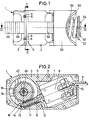
- Fig. 1
- eine Seitenansicht einer Motor-Getriebe-Einheit entsprechend den Sichtpfeilen I in der Fig. 2 und 3,
- Fig. 2
- einen Querschnitt durch die Motor-Getriebe-Einheit gemäß der Schnittlinie II-II in Fig. 3,
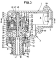
- Fig. 3
- einen Querschnitt durch die Motor-Getriebe-Einheit gemäß der Schnittlinie III-III In Fig. 1,
- Fig. 4
- eine Längsansieht eines Abtriebs-Hohlrades,
- Fig. 5
- eine Stirnansicht des Abtriebs-Hohlrades entsprechend dem Sichtpfeil V in Fig. 4, und
- Fig. 6
- eine Draufsicht auf eine Widerlager-Ringscheibe.
- Fig. 1
- 2 shows a side view of a motor-transmission unit in accordance with the arrows I in FIGS. 2 and 3,
- Fig. 2
- 3 shows a cross section through the motor / gear unit according to section line II-II in FIG. 3,
- Fig. 3
- 2 shows a cross section through the motor / gear unit according to section line III-III in FIG. 1,
- Fig. 4
- a longitudinal view of an output ring gear,
- Fig. 5
- an end view of the output ring gear according to the arrow V in Fig. 4, and
- Fig. 6
- a plan view of an abutment washer.
Die in der Zeichnung dargestellte Motor-Getriebe-Einheit weist ein aus einem Gehäuseunterteil 1 und einem Gehäuseoberteil 2 bestehendes, aus einem schweißfähigen thermoplastischen Kunststoff gebildetes Gehäuse auf, wobei die beiden Gehäuseteile mit aneinanderlegbaren Flanschen 3, 4 versehen sind. Der dem Gehäuseunterteil 1 zugewandte Flansch 3 ist mit Zentrierlöchern 5 versehen, während am Flansch 4 des Gehäuseoberteils 2 diesen Zentrierlöchern 5 zugeordnete Zapfen 6 ausgebildet sind, die in die Zentrierlöcher 5 eingeführt und nach der Montage und dem Zusammenstekken des Gehäuseunterteils 1 und des Gehäuseoberteils 2 verschweißt werden, so daß sie gleichzeitig auch zur festen Verbindung von Gehäuseunterteil 1 und Gehäuseoberteil 2 dienen.The motor-gear unit shown in the drawing has a housing which consists of a
Das Gehäuse 1, 2 ist mit einem Aufnahmeraum 7 für einen Elektromotor 8 versehen, dessen elektrische Versorgungs-Leitungen 9 durch eine Öffnung 10 in den Aufnahmeraum 7 geführt werden. Der Motor 8 ist drehrichtungsumkehrbar, also in beiden möglichen Drehrichtungen antreibbar.Der Elektromotor 8 liegt im Aufnahmeraum 7 gegen im Gehäuse ausgebildete Anschläge 11 an, ist also mit dem Einlegen in das Gehäuseunterteil 1 bereits in seiner Lage ausgerichtet.The
Der Elektromotor 8 ist mit einer aus dem Gehäuse 1, 2 frei vorragenden Welle 12 versehen, deren vom Elektromotor 8 entferntes freies Ende 13 in einer im Gehäuseunterteil 1 ausgeformten Lagerschale 14 abgestützt ist. Auf der aus Stahl bestehenden Welle 12 ist eine aus Kunststoff bestehende Zylinder-Schnecke 15 eines Schneckengetriebes 16 gegenüber der Welle 12 undrehbar, beispielsweise durch Preßsitz, angebracht.The
Die schraubenförmige Verzahnung 17 der Schnecke 15 greift in eine entsprechend angepaßte Verzahnung 18 eines Schneckenrades 19 ein, das zusammen mit der Schnecke 15 das Schneckengetriebe 16 bildet.The
Dem Schneckengetriebe 16 ist ein Planetengetriebe 20 nachgeordnet. Das Planetengetriebe 20 weist ein einstückig mit dem Schneckenrad 19 ausgebildetes, mit diesem also drehfest verbundenes Sonnenrad 21 auf, in dessen Außen-Verzahnung 22 drei Planetenräder 23, von denen nur eines dargestellt ist, mit ihrer entsprechenden Außen-Verzahnungen 24 eingreifen. Außerdem stützen die Planetenräder 23 sich an einem Hohlrad 25 ab, das mit einer Innen-Verzahnung 26 versehen ist, in die die jeweilige Außen-Verzahnung 24 der Planetenräder 23 eingreift. Das Hohlrad 25 ist gegenüber dem Gehäuse 1, 2 undrehbar, wozu es mit Vorsprüngen 27 an seinem Außenumfang versehen ist, die in angepaßte Ausnehmungen 28 im Gehäuse 1, 2 eingreifen. Die Planetenräder 23 sind auf Lagerzapfen 29 eines StegUnterteils 30 drehbar gelagert und werden dadurch in gleichen Winkelabständen zueinander gehalten.A
Die Planetenräder 23 sind jeweils einstückig mit einem Zahnrad 32 eines Hohlrad-Getriebes 33 ausgebildet. Die Außenverzahnung dieser Zahnräder 32 des Hohlrad-Getriebes 33 greifen in eine Innen-Verzahnung 35 eines Abtriebs-Hohlrades 36 des Hohlrad-Getriebes 33 ein. In die Zahnräder 32 greift jeweils ein Lagerzapfen 37 eines Steg-Oberteils 38 ein. Das Steg-Unterteil 30 und das Steg-Oberteil 38 sind mittels am Steg-Unterteil 30 ausgebildeter Aufnahmeöffnungen 39 und in diese eingreifende, am Steg-Oberteil 38 ausgebildeter Verbindungszapfen 40 miteinander zu einem gehäuseartigen Steg miteinander verbunden.The
Das Abtriebs-Hohlrad 36 weist einen einstückig mit diesem ausgebildeten zylindischen Lagerabschnitt 41 auf, der radial zur gemeinsamen Drehachse 42 des Schneckenrades 19, des Planetengetriebes 20 und des Hohlrad-Getriebes 33 in einer Lagerschale 43 gelagert ist, die am Gehäuseoberteil 3 ausgebildet ist. Das Abtriebs-Hohlrad 36 ist weiter in Richtung der Drehachse 42 relativ zum Gehäuseoberteil 2 durch sich radial zur Drehachse 42 erstreckende Anschlagflächen 44, 45 festgelegt, die die Drehung des Abtriebs-Hohlrades 36 nicht behindern, aber das Spiel, d.h. die Verschiebbarkeit des Hohlrades 36 in Richtung der Drehachse 42, auf etwa 0,1 mm beschränken.The
Das Schneckengetriebe 16, das Planetengetriebe 20 und das Hohlradgetriebe 33 bilden ein Untersetzungsgetriebe.The
Das Schneckenrad 19 ist auf einer durchgehenden zylindrischen Achse 46 aus Stahl gelagert, deren eines Ende in einer Aufnahme 47 im Gehäuseunterteil 1 mit Preßsitz, also gegenüber dem Gehäuseunterteil 1 undrehbar, gehalten ist. Das andere Ende der Achse 46 ist in einer zur Drehachse 42 korzentrischen, zylindrischen Ausnehmung 48 des Abtriebs-Hohlrades 36 radial zur Drehachse 42 weitgegehend spielfrei abgestützt, wobei aber die undrehbare Achse 46 die Drehung des Abtriebs-Hohlrades 46 nicht behindert. Das Schneckenrad 19 ist auf der Achse 46 frei drehbar gelagert und in Richtung der Drehachse 42 gegen die Stirnseite 49 der Aufnahme 47 in Richtung zum Gehäuseunterteil 1 abgestützt. In Richtung zum Abtriebs-Hohlrad 36 ist es axial am Hohlrad 25 des Planetengetriebes 20 abgestützt.The
Das insgesamt aus Metall, beispielsweise Zink-Guß, bestehende Abtriebs-Hohlrad 36 weist einen sich an den Lagerabschnitt 41 anschließenden, im wesentlichen zylindrischen Abtriebsabschnitt 50 auf, der mindestens eine, bevorzugt aber zwei einander diametral zur Drehachse 42 gegenüberliegende parallel zur Drehachse 42 verlaufende Längsnuten 51 aufweist. Auf dem Abtriebs-Abschnitt 50 ist ein Reibring 52 einer Rutschkupplung 53 angeordnet, der mit je einem Vorsprung 54 in die Längsnuten 51 eingreift, wodurch eine drehfeste Verbindung zwischen dem Abtriebs-Hohlrad 36 und dem Reibring 52 hergestellt wird. Der Reibring 52 liegt gegen einen Ringbund 55 am Übergang vom Lagerabschnitt 41 zum Abtriebsabschnitt 51 in Richtung der Drehachse 42 fest an. Er bildet die oben bereits angesprochene Anschlagfläche 45.The
Der Abtriebsabschnitt 50 ist von einem Abtriebs-Schwenkteil 56 umgeben, das eine parallel zur Drehachse 42 verlaufende Ausnehmung 57 aufweist, in die ein nicht dargestellter Bolzen eines zu verschwenkenden Teiles eingreifen kann. Das Abtriebs-Schwenkteil 56 weist eine Reibfläche 58 auf, die an einer Reibfläche 59 des Reibrings 52 anliegt. Beide Reibflächen 58, 59 sind kegelstumpfförmig ausgebildet und verjüngen sich vom Gehäuseoberteil 2 weg unter einem halben Kegelöffnungswinkel a. Es gilt 7° ≤ a ≤ 15° und bevorzugt a ≃ 10°.The
Das Abtriebs-Schwenkteil 56 wird mittels einer vorgespannten Schrauben-Druckfeder 60 in Richtung zum Reibring 52 gedrückt, wobei vom Schwenkteil 56 und dem Reibring 52 nur die Reibflächen 58, 59 aneinanderliegen. Zwischen diesen beiden Teilen wird also die erwähnte Rutschkupplung 53 gebildet, deren Rutsch-Moment durch den Reibungskoeffizienten zwischen der Reibfläche 59 des Reibrings 52 und der Reibfläche 58 des Schwenkteils 56 und durch die normal - also senkrecht - zu den Reibflächen 58, 59 wirkende Kraft und den mittleren Durchmesser d der Reibfläche 58, 59 bestimmt wird. Die zwischen den Reibflächen 58, 59 senkrecht zu ihnen wirkende Kraft ist bei einer vorgegebenen Kraft der Druckfeder 60 in Richtung der Drehachse 42 umso größer, je Kleiner der halbe Kegelöffnungswinkel a der Reibflächen 58, 59 ist. Die senkrecht zu den Reibflächen 58, 59 zwischen diesen wirkenden Kraft ist auf auf jeden Fall um ein Mehrfaches größer, also die Kraft der Druckfeder 60. Es kommt hinzu, daß der Reibring 52 aus Metall, beispielsweise aus Zink-Guß, besteht, während das Abtriebs-Schwenkteil 56 aus einem gängigen Kunststoff besteht.The
Die Schrauben-Druckfeder 60 liegt unter Zwischenschaltung einer als Druckscheibe 61 dienenden Ringscheibe gegen das Abtriebs-Schwenkteil 56 an. Diese Druckscheibe 61 ist ebenfalls in den Längsnuten 51 mittels Vorsprüngen 54 drehfest zum Abtriebs-Hohlrad 36 festgelegt. Das zwischen der Druckscheibe 61 und dem Schwenkteil 56 wirkende Reibmoment ist mindestens um den Quotienten 10 kleiner als das Rutschmoment der Rutschkupplung 53.The
Die Druckfeder 60 liegt weiterhin im Bereich des freien Endes 64 des Abtriebsabschnitts 50 gegen eine weitere, als Widerlager 62 dienende Ringscheibe an, die mit dem Abtriebsabschnitt 50 mittels eines Bajonettverschlusses 63 verriegelt ist. Die beiden Ringscheiben bestehen aus Metall, beispielsweise Stahl. Sie sind identisch ausgebildet und weisen den Längsnuten 51 angepaßte Vorsprünge 54 auf, die im Querschnitt identisch den Vorsprüngen 54 am Reibring 52 sind.The
Wie aus den Fig. 4 bis 6 in Verbindung mit Fig. 3 hervorgeht, ist zur Erzeugung des Bajonettverschlusses 63 im Bereich des freien Endes 64 des Abtriebs-Hohlrades 36 an dessen Abtriebsabschnitt 50 jeweils eine Teil-Umfangsnut 65 ausgebildet, die einseitig aus einer Längsnut 51 herausführt. Jede Teil-Umfangsnut 65 ist also an einem Ende 66 zu einer Längsnut 51 offen. Dagegen ist sie am anderen Ende 67 zu der jeweils anderen Längsnut 51 verschlossen. Jede Teil-Umfangsnut 65 weist eine zum freien Ende 64 hin gerichtete Ausnehmung 68 auf, die den Vorsprüngen 54 an der Widerlager-Ringscheibe 62 entsprechen.As can be seen from FIGS. 4 to 6 in connection with FIG. 3, in order to produce the
Alle Zahnräder, mit Ausnahme des Abtriebs-Hohlrades 36, bestehen aus Kunststoff und sind um die Drehachse 42 oder eine hierzu parallele Achse drehbar.All gearwheels, with the exception of the
Die Montage geht in der Weise vor sich, daß der Elektromotor 8 in den Aufnahmeraum 7 im Gehäuseunterteil 1 eingelegt und die Leitungen 9 durch die Öffnung 10 herausgeführt werden. Das freie Ende 13 der bereits mit der Schnecke 15 versehenen Welle 12 wird hierbei in die Lägerschale 14 eingesetzt. Zuvor oder nachher wird die Achse 46 in die Aufnahme 47 eingedrückt. Dann wird das Schneckenrad 19 des Planetengetriebes 20 auf die Achse aufgeschoben, bis es zur Anlage an der Stirnseite 49 der Aufnahme 47 kommt. Im Anschluß daran wird das Hohlrad 25 des Planetengetriebes 20 auf die Achse geschoben. Dann wird die vormontierte Einheit aus Steg-Unterteil 30, Planetenrädern 23 mit Zahnrädern 32 und Steg-Oberteil 38 derart in das Hohlrad 25 eingeschoben, daß die Außen-Verzahnungen 24 der Planetenräder 23 in Eingriff mit der Innen-Verzahnung 26 des Hohlrades 25 kommen. Danach wird das Abtriebs-Hohlrad auf die Achse 46 aufgeschoben, wobei gleichzeitig die Außen-Verzahnungen 34 der Zahnräder 32 mit der Innen-Verzahnung 35 des Abtriebs-Hohlrades 36 in Eingriff kommen. Außerdem wird die Achse 46 hierbei in der Ausnehmung 48 des Abtriebs-Hohlrades 36 aufgenommen und radial zur Drehachse 42 abgestützt. Im Anschluß daran wird das Gehäuse-Oberteil 2 auf das Gehäuse-Unterteil 1 aufgesetzt, wobei der Abtriebsabschnitt 50 durch die Lagerschale 43 hindurchgeführt wird. Die Zapfen 6 des Gehäuse-Oberteils 2 greifen hierbei in die Zentrierlöcher 5 des Gehäuse-Unterteils 1 ein und werden mit diesem, beispielsweise durch Ultraschall, verschweißt. Das Abtriebs-Hohlrad 36 ist jetzt mit seinem Lagerabschnitt 41 in der Lagerschale 43 des Gehäuse-Oberteils 2 radial gelagert. Im Anschluß daran wird der Reibring 52 der Rutsch-Kupplung 53 auf den Abtriebs-Abschnitt 50 aufgeschoben und dann das Abtriebs-Schwenkteil 56 aufgesetzt, so daß die beiden Reibflächen 58, 59 aneinanderliegen. Dann wird die Druckscheibe 61 auf den Abtriebsabschnitt 50 aufgeschoben und die Schrauben-Druckfeder 60 ebenfalls auf den Abtriebs-Abschnitt 50 aufgesetzt. Mittels der Widerlager-Ringscheibe 62 wird anschließend die Schrauben-Druckfeder 60 in Richtung zum Reibring 52 vorgespannt und die Widerlager-Ringscheibe 62 mittels des Bajonettverschlusses 63 mit dem Abtriebsanschnitt 50 verriegelt. Hierzu wird die Widerlager-Ringscheibe 62 unter Zusammendrücken der Druckfeder 60 auf das freie Emde 64 des Abtriebsabschnitts 50 aufgeschoben und nach Erreichen der Teil-Umfangsnuten 65 derart verdreht, daß die Vorsprünge 54 in diese Teil-Umfangsnuten 65 gelangen und zwar bis zu deren Anschlag am verschlossenen Ende 67. Wenn jetzt die Widerlager-Ringscheibe 62 entlastet wird, wird sie soweit in Richtung zum freien Ende 64 zurückgeschoben, bis ihre Vorsprünge 54 in den Ausnehmungen 68 zur Anlage kommen. In diesen Ausnehmungen 68 ist dann die Widerlager-Ringscheibe 62 gegenüber dem Abtriebsabschnitt 50 unverdrehbar, kann also nicht lediglich durch Drehen gelöst werden, und zwar unabhängig davon, in welcher Richtung der Abtriebsabschnitt 50 mit dem Abtriebs-Schwenkteil 56 um die Drehachse 42 verdreht wird.The assembly takes place in such a way that the
Die fertig montierte Motor-Getriebe-Einheit kann mittels am Gehäuse 1, 2 ausgebildeter Befestigungsöffnungen 69 für einen entsprechenden Einsatz montiert werden. Ein solcher Einsatz erfolgt beispielsweise in Außenspiegeln von Kraftfahrzegen und zwar insbesondere in Außenspiegeln für Lastkraftwagen vorgesehen.The fully assembled motor-gear unit can be mounted for appropriate use by means of
Claims (6)
Applications Claiming Priority (2)
| Application Number | Priority Date | Filing Date | Title |
|---|---|---|---|
| DE19615002 | 1996-04-16 | ||
| DE19615002A DE19615002A1 (en) | 1996-04-16 | 1996-04-16 | Gear unit |
Publications (1)
| Publication Number | Publication Date |
|---|---|
| EP0802084A1 true EP0802084A1 (en) | 1997-10-22 |
Family
ID=7791426
Family Applications (1)
| Application Number | Title | Priority Date | Filing Date |
|---|---|---|---|
| EP97104374A Withdrawn EP0802084A1 (en) | 1996-04-16 | 1997-03-14 | Transmission unit |
Country Status (4)
| Country | Link |
|---|---|
| US (1) | US6283863B1 (en) |
| EP (1) | EP0802084A1 (en) |
| DE (1) | DE19615002A1 (en) |
| MX (1) | MX9702765A (en) |
Families Citing this family (12)
| Publication number | Priority date | Publication date | Assignee | Title |
|---|---|---|---|---|
| DE19953484C2 (en) * | 1999-11-06 | 2002-03-07 | Oechsler Ag | Disengageable swivel drive |
| JP3482400B2 (en) * | 2001-04-18 | 2003-12-22 | 川崎重工業株式会社 | Power transmission device for off-road vehicles |
| DE10141240A1 (en) * | 2001-08-23 | 2003-03-06 | Trw Repa Gmbh | Belt spooler for motor vehicle safety belts with geared motor, has reduction gear that can be selectively connected to belt spool on output side via controllable coupling |
| DE10251057B4 (en) * | 2002-11-02 | 2006-06-22 | Julius Cronenberg Offene Handelsgesellschaft | Retractor for straps or the like |
| US20050219722A1 (en) * | 2004-01-13 | 2005-10-06 | Craig Watrous | Clutch assembly for breakaway mirror |
| DE102005012652A1 (en) * | 2005-03-18 | 2006-10-05 | Ejot Gmbh & Co. Kg | slip clutch |
| US7966904B2 (en) | 2006-05-05 | 2011-06-28 | Questek Manufacturing Corporation | Low axial play drive system |
| DE102013220233A1 (en) * | 2013-10-08 | 2015-04-09 | Robert Bosch Gmbh | Machine tool system |
| DE102015218377A1 (en) | 2015-09-24 | 2017-03-30 | Schaeffler Technologies AG & Co. KG | Hohlradgetriebe |
| JP6618415B2 (en) * | 2016-04-08 | 2019-12-11 | 株式会社東海理化電機製作所 | Vehicle visual recognition device |
| NL2018838B1 (en) | 2017-05-03 | 2018-11-14 | Mci Mirror Controls Int Netherlands B V | Adjustment instrument and method |
| DE102017129186B4 (en) * | 2017-12-07 | 2021-07-01 | Motherson Innovations Company Limited | Rearview device for a motor vehicle, assembly method therefor and motor vehicle with a rearview device |
Citations (8)
| Publication number | Priority date | Publication date | Assignee | Title |
|---|---|---|---|---|
| GB139648A (en) * | 1919-04-02 | 1920-03-11 | William Turton | Improvements in self releasing holders for screw cutting taps or dies |
| DE468386C (en) * | 1927-04-22 | 1928-11-12 | Henri Bertauld | Machine for conveying grain |
| US2569144A (en) * | 1946-11-21 | 1951-09-25 | T M K Corp | Overload release friction coupling |
| GB2054496A (en) * | 1979-08-04 | 1981-02-18 | Kienzle Uhrenfabriken Gmbh | Remotely controlled rear-view mirrors |
| GB2064682A (en) * | 1979-12-12 | 1981-06-17 | Hilti Ag | Friction clutch for transmitting limited torque |
| FR2509236A1 (en) * | 1981-07-09 | 1983-01-14 | Berex | Transmission for all-wheel drive, cross-country vehicle - comprises propeller shaft which drives another one via torque limiting mechanism in gearbox |
| US4880407A (en) * | 1988-02-16 | 1989-11-14 | Custom Products Corporation | Cone clutch |
| WO1991004172A1 (en) * | 1989-09-14 | 1991-04-04 | Iku Holding Montfoort B.V. | Mirror housing pivoting mechanism for a vehicle rear view mirror |
Family Cites Families (33)
| Publication number | Priority date | Publication date | Assignee | Title |
|---|---|---|---|---|
| DE7627888U1 (en) * | 1900-01-01 | Julius Bauser Kg, Kontrolluhrenfabrik, 7241 Empfingen | ||
| US2901912A (en) * | 1958-01-02 | 1959-09-01 | Bendix Aviat Corp | Engine starter gearing |
| US2974503A (en) * | 1958-02-21 | 1961-03-14 | Alan R Newton | Torque limiting device |
| US3265362A (en) | 1964-03-02 | 1966-08-09 | Warren E Moody | Hoisting devices |
| US3648483A (en) * | 1970-06-01 | 1972-03-14 | Gen Electric | Overload friction coupling |
| JPS5511210Y2 (en) * | 1974-04-18 | 1980-03-11 | ||
| IT1026359B (en) * | 1975-01-15 | 1978-09-20 | Spem Srl | CONSTANT LOAD CLUTCH DEVICE ESPECIALLY SUITABLE FOR APPLICATION IN TAPE RECORDERS |
| JPS6047130B2 (en) | 1975-08-14 | 1985-10-19 | 市光工業株式会社 | Chestnut dual-use rear view mirror |
| US4133344A (en) | 1976-06-10 | 1979-01-09 | The Toro Company | Power transmission for self-propelled irrigation system |
| DE2820541C2 (en) * | 1978-05-11 | 1986-10-09 | Bernhard Dipl.-Wirtsch.-Ing. 3002 Wedemark Mittelhäuser | Exterior rearview mirrors for automobiles |
| DE2846586A1 (en) * | 1978-10-26 | 1980-05-08 | Kienzle Uhrenfabriken Gmbh | Remote adjustment vehicle outer rear mirror - has two servomotors and epicyclic reduction gears and slip clutches for connection to two cranks |
| DE3013009A1 (en) * | 1980-04-03 | 1981-10-08 | Gustav Magenwirth Gmbh & Co, 7432 Urach | Servo driven wing mirror with limited slip - has ball bearing coupling with axial sprung races |
| DE3412338C2 (en) * | 1983-09-21 | 1986-07-31 | Rhein-Getriebe Gmbh, 4005 Meerbusch | Worm gear |
| DE3434905A1 (en) | 1984-09-22 | 1986-04-03 | SWF Auto-Electric GmbH, 7120 Bietigheim-Bissingen | DRIVE UNIT, ESPECIALLY FOR ADJUSTING WINDOW WINDOWS, SLIDING ROOFS, SEATS AND SIMILAR MOTOR VEHICLE PARTS |
| US4699024A (en) | 1985-05-21 | 1987-10-13 | Aisin Seiki Kabushiki Kaisha | Device for adjusting the angular position of one member relative to another |
| US4641887A (en) | 1985-09-16 | 1987-02-10 | Keiper Recaro Incorporated | Planetary seat back adjuster |
| US4660247A (en) * | 1985-12-31 | 1987-04-28 | Whirlpool Corporation | Temperature limiting system for a spring loaded torque limiting clutch |
| DE3741615A1 (en) | 1987-12-09 | 1989-06-22 | Reitter & Schefenacker Kg | Electric motor drive for window lifters of motor vehicles |
| US4921083A (en) | 1989-02-28 | 1990-05-01 | Square D Company | Clutch module with predetermined torque |
| DE3914334C2 (en) * | 1989-04-29 | 1994-08-04 | Kienzle Uhrenfabriken Gmbh | Adjustment device for a vehicle exterior mirror |
| JP2515645Y2 (en) | 1989-11-21 | 1996-10-30 | アスモ 株式会社 | Motor with reduction gear |
| IT220513Z2 (en) * | 1990-05-15 | 1993-09-24 | Gilardini Spa | REAR-VIEW MIRROR FOR A VEHICLE. |
| JPH0689788B2 (en) * | 1990-05-30 | 1994-11-14 | 株式会社椿本エマソン | Slip clutch |
| JPH0463738A (en) | 1990-07-04 | 1992-02-28 | Ichikoh Ind Ltd | Electrically-driven stay housing type mirror device |
| DE4119748C2 (en) * | 1991-06-15 | 1994-06-09 | Luchtenberg Gmbh & Co | Folding rear-view mirror |
| IT1252140B (en) * | 1991-11-29 | 1995-06-05 | Commer Spa | DEVICE FOR THE CONTROLLED ROTATION OF AN EXTERNAL REAR-VIEW MIRROR |
| JPH05222245A (en) * | 1992-02-10 | 1993-08-31 | Tokai Carbon Co Ltd | Rubber composition |
| NL9202266A (en) | 1992-12-24 | 1994-07-18 | Iku Holding Montfoort Bv | Mirror folding mechanism, and vehicle provided with such a mirror folding mechanism. |
| DE4311355C2 (en) * | 1993-04-06 | 1995-01-26 | Stephan Werke Gmbh & Co | Worm gear |
| DE4324876C2 (en) * | 1993-07-23 | 1995-06-01 | Ims Morat Soehne Gmbh | Gear and its use |
| JPH07195979A (en) * | 1993-12-28 | 1995-08-01 | Sakae Riken Kogyo Kk | Electric folding type mirror |
| JP3423411B2 (en) | 1994-06-09 | 2003-07-07 | 株式会社リコー | Manufacturing method of helical spiral cam |
| JP3323686B2 (en) | 1995-01-10 | 2002-09-09 | アスモ株式会社 | Moving object position detection device |
-
1996
- 1996-04-16 DE DE19615002A patent/DE19615002A1/en not_active Withdrawn
-
1997
- 1997-03-14 EP EP97104374A patent/EP0802084A1/en not_active Withdrawn
- 1997-04-04 US US08/832,936 patent/US6283863B1/en not_active Expired - Lifetime
- 1997-04-16 MX MX9702765A patent/MX9702765A/en unknown
Patent Citations (8)
| Publication number | Priority date | Publication date | Assignee | Title |
|---|---|---|---|---|
| GB139648A (en) * | 1919-04-02 | 1920-03-11 | William Turton | Improvements in self releasing holders for screw cutting taps or dies |
| DE468386C (en) * | 1927-04-22 | 1928-11-12 | Henri Bertauld | Machine for conveying grain |
| US2569144A (en) * | 1946-11-21 | 1951-09-25 | T M K Corp | Overload release friction coupling |
| GB2054496A (en) * | 1979-08-04 | 1981-02-18 | Kienzle Uhrenfabriken Gmbh | Remotely controlled rear-view mirrors |
| GB2064682A (en) * | 1979-12-12 | 1981-06-17 | Hilti Ag | Friction clutch for transmitting limited torque |
| FR2509236A1 (en) * | 1981-07-09 | 1983-01-14 | Berex | Transmission for all-wheel drive, cross-country vehicle - comprises propeller shaft which drives another one via torque limiting mechanism in gearbox |
| US4880407A (en) * | 1988-02-16 | 1989-11-14 | Custom Products Corporation | Cone clutch |
| WO1991004172A1 (en) * | 1989-09-14 | 1991-04-04 | Iku Holding Montfoort B.V. | Mirror housing pivoting mechanism for a vehicle rear view mirror |
Also Published As
| Publication number | Publication date |
|---|---|
| MX9702765A (en) | 1998-04-30 |
| US6283863B1 (en) | 2001-09-04 |
| DE19615002A1 (en) | 1997-10-23 |
Similar Documents
| Publication | Publication Date | Title |
|---|---|---|
| DE3510605C2 (en) | ||
| EP1989096B1 (en) | Helical bevel gear for a rack-and-pinion steering system | |
| WO2012028283A1 (en) | Adjustment drive for adjustment devices of a motor vehicle seat | |
| DE3019524A1 (en) | COMPACT GEARBOX FOR ONE WINDOW OPERATOR | |
| EP0802084A1 (en) | Transmission unit | |
| DE102019209470B4 (en) | Parking lock arrangement with parking lock gear and torsion damper | |
| EP2345569A1 (en) | Screw gearing for the steering of a motor vehicle | |
| EP0802348B1 (en) | Transmission unit | |
| DE3700678A1 (en) | WIPER MOTOR | |
| DE102004008538B4 (en) | Differential with a bolt mounting assembly | |
| EP1728307B1 (en) | Rotation drive | |
| DE4302726C2 (en) | Toothed shaft connection and method for producing a toothed shaft connection | |
| DE19945255A1 (en) | Wheel bearings, especially for non-driven vehicle axles | |
| WO2002006097A1 (en) | Wiper system | |
| EP3143294A1 (en) | Device for securing a tension element against unintentional release | |
| EP0918931B1 (en) | Electromotor/pump assembly | |
| EP0989655A2 (en) | Electric motor linear drive | |
| WO2022083982A1 (en) | Eccentric gear unit for a braking force generator, and braking force generator | |
| DE4308975C2 (en) | Shaft-hub connection | |
| DE3045560C2 (en) | Drive device for windshield wipers on motor vehicles | |
| DE102004044753B4 (en) | Tilt adjustment fitting for the backrest of a motor vehicle seat | |
| DE102021211648B4 (en) | shaft-hub connection | |
| DE19650716C1 (en) | Eccentric transmission | |
| DE4317954C2 (en) | Drive device | |
| EP3765758B1 (en) | Helical gear transmission comprising a pivot bearing with a defined pivot axis |
Legal Events
| Date | Code | Title | Description |
|---|---|---|---|
| PUAI | Public reference made under article 153(3) epc to a published international application that has entered the european phase |
Free format text: ORIGINAL CODE: 0009012 |
|
| AK | Designated contracting states |
Kind code of ref document: A1 Designated state(s): DE ES FR GB IT SE |
|
| 17P | Request for examination filed |
Effective date: 19980318 |
|
| 17Q | First examination report despatched |
Effective date: 19990921 |
|
| STAA | Information on the status of an ep patent application or granted ep patent |
Free format text: STATUS: THE APPLICATION IS DEEMED TO BE WITHDRAWN |
|
| 18D | Application deemed to be withdrawn |
Effective date: 20010317 |