EP0802348B1 - Transmission unit - Google Patents
Transmission unitInfo
- Publication number
- EP0802348B1 EP0802348B1 EP97104375A EP97104375A EP0802348B1 EP 0802348 B1 EP0802348 B1 EP 0802348B1 EP 97104375 A EP97104375 A EP 97104375A EP 97104375 A EP97104375 A EP 97104375A EP 0802348 B1 EP0802348 B1 EP 0802348B1
- Authority
- EP
- European Patent Office
- Prior art keywords
- gear
- piece
- turning axis
- axle
- worm
- Prior art date
- Legal status (The legal status is an assumption and is not a legal conclusion. Google has not performed a legal analysis and makes no representation as to the accuracy of the status listed.)
- Expired - Lifetime
Links
- 230000005540 biological transmission Effects 0.000 title description 2
- 229910000831 Steel Inorganic materials 0.000 claims description 4
- 239000002184 metal Substances 0.000 claims description 4
- 229910052751 metal Inorganic materials 0.000 claims description 4
- 239000010959 steel Substances 0.000 claims description 4
- 230000006835 compression Effects 0.000 description 8
- 238000007906 compression Methods 0.000 description 8
- 238000005452 bending Methods 0.000 description 4
- 239000004033 plastic Substances 0.000 description 3
- HCHKCACWOHOZIP-UHFFFAOYSA-N Zinc Chemical compound [Zn] HCHKCACWOHOZIP-UHFFFAOYSA-N 0.000 description 2
- 229910052725 zinc Inorganic materials 0.000 description 2
- 239000011701 zinc Substances 0.000 description 2
- 238000003780 insertion Methods 0.000 description 1
- 230000037431 insertion Effects 0.000 description 1
- 238000002372 labelling Methods 0.000 description 1
- 230000002441 reversible effect Effects 0.000 description 1
- 229920001169 thermoplastic Polymers 0.000 description 1
- 239000004416 thermosoftening plastic Substances 0.000 description 1
- 230000007704 transition Effects 0.000 description 1
- 238000002604 ultrasonography Methods 0.000 description 1
Images


Classifications
-
- B—PERFORMING OPERATIONS; TRANSPORTING
- B60—VEHICLES IN GENERAL
- B60R—VEHICLES, VEHICLE FITTINGS, OR VEHICLE PARTS, NOT OTHERWISE PROVIDED FOR
- B60R1/00—Optical viewing arrangements; Real-time viewing arrangements for drivers or passengers using optical image capturing systems, e.g. cameras or video systems specially adapted for use in or on vehicles
- B60R1/02—Rear-view mirror arrangements
- B60R1/06—Rear-view mirror arrangements mounted on vehicle exterior
- B60R1/062—Rear-view mirror arrangements mounted on vehicle exterior with remote control for adjusting position
- B60R1/07—Rear-view mirror arrangements mounted on vehicle exterior with remote control for adjusting position by electrically powered actuators
- B60R1/074—Rear-view mirror arrangements mounted on vehicle exterior with remote control for adjusting position by electrically powered actuators for retracting the mirror arrangements to a non-use position alongside the vehicle
-
- F—MECHANICAL ENGINEERING; LIGHTING; HEATING; WEAPONS; BLASTING
- F16—ENGINEERING ELEMENTS AND UNITS; GENERAL MEASURES FOR PRODUCING AND MAINTAINING EFFECTIVE FUNCTIONING OF MACHINES OR INSTALLATIONS; THERMAL INSULATION IN GENERAL
- F16H—GEARING
- F16H1/00—Toothed gearings for conveying rotary motion
- F16H1/02—Toothed gearings for conveying rotary motion without gears having orbital motion
- F16H1/04—Toothed gearings for conveying rotary motion without gears having orbital motion involving only two intermeshing members
- F16H1/12—Toothed gearings for conveying rotary motion without gears having orbital motion involving only two intermeshing members with non-parallel axes
- F16H1/16—Toothed gearings for conveying rotary motion without gears having orbital motion involving only two intermeshing members with non-parallel axes comprising worm and worm-wheel
-
- H—ELECTRICITY
- H02—GENERATION; CONVERSION OR DISTRIBUTION OF ELECTRIC POWER
- H02K—DYNAMO-ELECTRIC MACHINES
- H02K7/00—Arrangements for handling mechanical energy structurally associated with dynamo-electric machines, e.g. structural association with mechanical driving motors or auxiliary dynamo-electric machines
- H02K7/06—Means for converting reciprocating motion into rotary motion or vice versa
Definitions
- the invention relates to a gear unit according to the preamble of Claim 1.
- Such gear units are usually called motor gear units trained, i.e. On the one hand, there is an electric motor in a housing and, on the other hand, a downstream multi-stage reduction gear arranged.
- motor-transmission units are, for example as servomotors for exterior mirrors of motor vehicles, in particular for Exterior mirrors of trucks, used. So they are proportionate small and only serve to transmit small torques.
- gear unit of the generic type that is Worm wheel rotatably mounted on a pin of the first housing part; the driven part is radially interposed in the second housing part of a bearing ring
- the remaining gear parts between the worm gear and the driven part are essentially self-centering.
- the assembly of this gear unit is associated with some effort. Otherwise, the gear unit is susceptible to wear.
- a generic transmission unit is known from DE 37 41 615 A1. At this is arranged in a gearbox in the middle of an axis that supports the bearing for a worm gear driven by a worm and a planetary gear forms.
- the gear housing is through a cooperating with the planetary gear Ring gear closed, the only in a closing ring axial direction is set.
- the gear unit is used for pivoting a scissor drive arm for the window regulator of a motor vehicle, d. H. the Scissor output arm is pivoted on one level.
- the ring gear is opposite the gear housing, but not radially against the end ring.
- the axis in the gearbox is not in to accommodate Bending moments set appropriately.
- the invention has for its object a gear unit of the generic type Art to design so that it is low wear and friction runs and is easy to assemble.
- the axis is used in the multi-stage reduction gear occurring bending forces, in particular bending forces arising from the worm wheel to absorb the extends over the full length of the multi-stage reduction gear and is mounted on both ends.
- bending forces from this Axis are included, they do not come in the range of numerous Gears, on the one hand, which means that they do not go beyond normal friction Frictional forces occur and also one caused thereby Wear is avoided. Assembly is made easier because all components of the reduction gear are pushed over the axis.
- Claims 2 and 3 give advantageous configurations of the attachment or storage of the axis and its training itself again.
- the motor-transmission unit shown in the drawing has one an existing lower housing part 1 and an upper housing part 2 a weldable thermoplastic housing, the two housing parts being provided with flanges 3, 4 which can be put together are.
- the flange 3 facing the lower housing part 1 has centering holes 5 provided while on the flange 4 of the upper housing part 2 these centering holes 5 associated pins 6 are formed, which in the centering holes 5 inserted and after assembly and assembly the lower housing part 1 and the upper housing part 2 welded be, so that they also at the same time for the firm connection of the lower housing part 1 and upper housing part 2 serve.
- the housing 1, 2 has a receiving space 7 for an electric motor 8 provided whose electrical supply lines 9 through an opening 10 are guided into the receiving space 7.
- the motor 8 is reversible in the direction of rotation, So it can be driven in both possible directions of rotation 8 lies in the receiving space 7 against stops formed in the housing 11, is already with the insertion in the lower housing part 1 aligned in its location.
- the electric motor 8 is freely projecting from the housing 1, 2 Provide shaft 12, the free end 13 in removed from the electric motor 8 in a bearing shell 14 formed in the lower housing part 1 is supported.
- On the steel shaft 12 is an existing plastic Cylindrical worm 15 of a worm gear 16 with respect to shaft 12 rotatable, for example by a press fit.
- the helical toothing 17 of the worm 15 engages accordingly adapted teeth 18 of a worm wheel 19 that together forms the worm gear 16 with the worm 15.
- a planetary gear 20 is arranged downstream of the worm gear 16.
- the Planetary gear 20 has a one-piece design with the worm wheel 19, with this so rotatably connected sun gear 21, in the External teeth 22 three planet gears 23, only one of which is shown, engage with their corresponding external teeth 24.
- the planet gears 23 are supported on a ring gear 25, which is provided with an internal toothing 26 into which the respective External toothing 24 of the planet gears 23 engages.
- the ring gear 25 is relative to the housing 1, 2 non-rotatable, for which purpose it has projections 27 its outer circumference is provided, which in adapted recesses 28 in Intervene in housing 1, 2.
- the planet gears 23 are on journals 29 of a web lower part 30 rotatably mounted and are thereby in the same Angular distances from each other.
- the planet gears 23 are each in one piece with a gear 32 Ring gear 33 is formed.
- the external teeth of these gears 32 of the ring gear 33 engage in an internal toothing 35 of a Output ring gear 36 of the ring gear 33.
- In the gears 32 engages in each case a journal 37 of a web upper part 38.
- the lower part of the web 30 and the web upper part 38 are by means of the web lower part 30 trained receiving openings 39 and engaging in these, on the web top 38 trained connecting pin 40 together to form a housing-like Bridge connected to each other.
- the output ring gear 36 has an integrally formed with it cylindrical bearing section 41, the radial to the common axis of rotation 42 of the worm wheel 19, the planetary gear 20 and the ring gear 33 is mounted in a bearing shell 43 which is on the upper housing part 3 is trained.
- the output ring gear 36 is further in the direction of the axis of rotation 42 relative to the upper housing part 2 by itself radially to the axis of rotation 42 extending stop surfaces 44, 45 set the rotation of the Output ring gear 36 does not hinder, but the game, i.e. the movability of the ring gear 36 in the direction of the axis of rotation 42, approximately Limit 0.1 mm.
- the worm gear 16, the planetary gear 20 and the ring gear 33 form a reduction gear.
- the worm wheel 19 is on a continuous cylindrical axis 46 made of steel, one end of which in a receptacle 47 in the lower housing part 1 with a press fit, i.e. non-rotatable relative to the lower housing part 1, is held.
- the other end of the axis 46 is in one to the axis of rotation 42 concentric, cylindrical recess 48 of the output ring gear 36 supported radially to the axis of rotation 42 largely without play, but the non-rotatable axis 46 does not hinder the rotation of the output ring gear 46.
- the worm wheel 19 is freely rotatable on the axis 46 and in the direction of the axis of rotation 42 against the end face 49 of the receptacle 47 in Supported towards the lower housing part 1.
- Towards the output ring gear 36 it is axially supported on the ring gear 25 of the planetary gear 20.
- the entire output ring gear made of metal, such as cast zinc 36 has an adjoining the bearing section 41 in the substantially cylindrical output section 50, the at least one, but preferably two diametrically opposite to the axis of rotation 42 has longitudinal grooves 51 running parallel to the axis of rotation 42.
- a friction ring 52 of a slip clutch 53 is arranged, which engages with a projection 54 in the longitudinal grooves 51, whereby a rotationally fixed connection between the output ring gear 36 and the friction ring 52 is produced.
- the friction ring 52 lies against an annular collar 55 at the transition from the bearing section 41 to the driven section 51 in Direction of the axis of rotation 42 on. It forms the one already mentioned above Stop surface 45.
- the output section 50 is surrounded by an output pivoting part 56, which has a recess 57 running parallel to the axis of rotation 42, in which a bolt, not shown, of a part to be pivoted can intervene.
- the output pivoting part 56 has a friction surface 58, which rests on a friction surface 59 of the friction ring 52. Both friction surfaces 58, 59 are frustoconical and taper from the top of the housing 2 way under half a cone opening a. There is 7 ° ⁇ a ⁇ 15 ° and preferably a ⁇ 10 °.
- the output pivot part 56 is by means of a preloaded compression coil spring 60 pressed towards the friction ring 52, from the swivel part 56 and the friction ring 52, only the friction surfaces 58, 59 lie against one another.
- the above-mentioned slip clutch 53 is therefore between these two parts formed, the slip moment by the coefficient of friction between the friction surface 59 of the friction ring 52 and the friction surface 58 of the pivoting part 56 and through the normal - i.e. perpendicular - to the friction surfaces 58, 59 acting force and the average diameter d of the friction surface 58, 59 determined becomes.
- the one acting between the friction surfaces 58, 59 perpendicular to them Force is at a predetermined force of the compression spring 60 in the direction of the axis of rotation 42, the smaller the half the cone opening angle a of the friction surfaces 58, 59.
- the perpendicular to the friction surfaces 58, 59 between these forces is definitely a multiple larger, that is, the force of the compression spring 60.
- the Friction ring 52 made of metal, such as cast zinc, is made during the output pivoting part 56 consists of a common plastic.
- the helical compression spring 60 is interposed as a Washer 61 serving washer against the output swivel 56th on.
- This thrust washer 61 is also in the longitudinal grooves 51 by means of projections 54 rotatably fixed to the output ring gear 36. That between the Thrust washer 61 and the pivoting part 56 acting friction torque is at least by the quotient 10 less than the slip torque of the slip clutch 53.
- the compression spring 60 is also in the region of the free end 64 of the output section 50 against another ring disk serving as abutment 62 to that with the output section 50 by means of a bayonet lock 63 is locked.
- the two washers are made of metal, for example steel. They are identical and have the Longitudinal grooves 51 adapted projections 54 which are identical in cross section the projections 54 on the friction ring 52.
- each partial circumferential groove 65 is thus at one end 66 to form a longitudinal groove 51 open. In contrast, it is at the other end 67 to the other Longitudinal groove 51 closed.
- Each partial circumferential groove 65 has one for free End 64 directed towards recess 68 on the projections 54 correspond to the abutment washer 62.
- All gears with the exception of the output ring gear 36, consist of Plastic and are about the axis of rotation 42 or an axis parallel thereto rotatable.
- the assembly proceeds in such a way that the electric motor 8 in the Receiving space 7 inserted in the lower housing part 1 and the lines 9 can be led out through the opening 10.
- the free end 13 of the already with the screw 15 provided shaft 12 is in the bearing shell 14 used.
- the worm wheel 19 of the planetary gear 20 is on the axis pushed on until it rests against the front 49 of the receptacle 47 is coming. Subsequently, the ring gear 25 of the planetary gear 20 pushed onto the axis.
- the pin 6 of the upper housing part 2 engage in the centering holes 5 of the lower housing part 1 and are welded to it, for example by ultrasound.
- the Output ring gear 36 is now with its bearing section 41 in the bearing shell 43 of the upper housing part 2 is mounted radially.
- the friction ring 52 of the slip clutch 53 on the output section 50 pushed on and then the output swivel part 56 placed so that the two friction surfaces 58, 59 lie against one another.
- the thrust washer 61 pushed onto the output section 50 and the helical compression spring 60 also placed on the output section 50.
- the abutment washer 62 then becomes the helical compression spring 60 biased towards the friction ring 52 and the abutment washer 62 by means of the bayonet catch 63 with the driven gate 50 locked.
- the abutment washer 62 is pressed together the compression spring 60 onto the free end 64 of the output section 50 pushed on and rotated after reaching the partial circumferential grooves 65 in such a way that the projections 54 get into these partial circumferential grooves 65 and until it stops at the closed end 67. If now the Abutment washer 62 is relieved, it is so far towards free end 64 pushed back until their projections 54 in the recesses 68 come to the plant. In these recesses 68 is then Abutment washer 62 cannot be rotated relative to the driven section 50, can not be solved by turning only regardless of the direction in which the output section 50 with the Output pivot part 56 is rotated about the axis of rotation 42.
- the fully assembled motor-gear unit can be attached to the housing 1, 2 trained mounting holes 69 for a corresponding use to be assembled.
- Such an application takes place, for example, in exterior mirrors of motor vehicles, in particular in exterior mirrors for Trucks provided.
Landscapes
- Engineering & Computer Science (AREA)
- Mechanical Engineering (AREA)
- General Engineering & Computer Science (AREA)
- Multimedia (AREA)
- Power Engineering (AREA)
- Gear Transmission (AREA)
- Toys (AREA)
- Transmission Devices (AREA)
Description
Die Erfindung betrifft eine Getriebe-Einheit nach dem Oberbegriff des
Anspruches 1.The invention relates to a gear unit according to the preamble of
Derartige Getriebe-Einheiten werden in der Regel als Motor-Getriebe-Einheiten ausgebildet, d.h. in einem Gehäuse ist einerseits ein Elektromotor und andererseits ein diesem nachgeordnetes mehrstufiges Untersetzungs-Getriebe angeordnet. Derartige Motor-Getriebe-Einheiten werden beispielsweise als Stellmotoren bei Außenspiegeln von Kraftfahrzeugen, insbesondere bei Außenspiegeln von Lastkraft-Fahrzeugen, eingesetzt. Sie sind also verhältnismäßig klein und dienen nur zur Übertragung kleiner Drehmomente.Such gear units are usually called motor gear units trained, i.e. On the one hand, there is an electric motor in a housing and, on the other hand, a downstream multi-stage reduction gear arranged. Such motor-transmission units are, for example as servomotors for exterior mirrors of motor vehicles, in particular for Exterior mirrors of trucks, used. So they are proportionate small and only serve to transmit small torques.
Bei einer bekannten Getriebe-Einheit der gattungsgemäßen Art ist das Schneckenrad auf einem Zapfen des ersten Gehäuseteils drehbar gelagert; das Abtriebsteil ist im zweiten Gehäuseteil radial unter Zwischenschaltung eines Lagerrings gelagert Die übrigen Getriebeteile zwischen dem Schnekkenrad und dem Abtriebsteil sind im wesentlichen selbstzentrierend ausgebildet. Die Montage dieser Getriebe-Einheit ist mit einigem Aufwand verbunden. Im übrigen ist die Getriebe-Einheit verschleißanfällig.In a known gear unit of the generic type that is Worm wheel rotatably mounted on a pin of the first housing part; the driven part is radially interposed in the second housing part of a bearing ring The remaining gear parts between the worm gear and the driven part are essentially self-centering. The assembly of this gear unit is associated with some effort. Otherwise, the gear unit is susceptible to wear.
Eine gattungsgemäße Getriebe-Einheit ist aus der DE 37 41 615 A1 bekannt. Bei dieser ist in einem Getriebegehäuse mittig eine Achse angeordnet, die die Lagerung für ein über eine Schnecke angetriebenes Schneckenrad und ein Planetengetriebe bildet. Das Getriebegehäuse ist durch ein mit dem Planetengetriebe zusammengewirkendes Hohlrad verschlossen, das über einen Abschlußring nur in axialer Richtung festgelegt ist. Die Getriebe-Einheit dient der Verschwenkung eines Scherenabtriebsarmes für den Fensterheber eines Kraftfahrzeugs, d. h. der Scherenabtriebsarm wird in einer Ebene verschwenkt. Das Hohlrad ist gegenüber dem Getriebegehäuse, nicht jedoch gegenüber dem Abschlußring radial gelagert. Darüber hinaus ist die Achse im Getriebegehäuse nicht in zur Aufnahme von Biegemomenten geeigneter Weise festgelegt.A generic transmission unit is known from DE 37 41 615 A1. At this is arranged in a gearbox in the middle of an axis that supports the bearing for a worm gear driven by a worm and a planetary gear forms. The gear housing is through a cooperating with the planetary gear Ring gear closed, the only in a closing ring axial direction is set. The gear unit is used for pivoting a scissor drive arm for the window regulator of a motor vehicle, d. H. the Scissor output arm is pivoted on one level. The ring gear is opposite the gear housing, but not radially against the end ring. In addition, the axis in the gearbox is not in to accommodate Bending moments set appropriately.
Der Erfindung liegt die Aufgabe zugrunde, eine Getriebe-Einheit der gattungsgemäßen Art so auszugestalten, daß es verschleiß- und reibungsarm läuft und leicht zu montieren ist. The invention has for its object a gear unit of the generic type Art to design so that it is low wear and friction runs and is easy to assemble.
Diese Aufgabe wird erfindungsgemäß durch die Merkmale im Kennzeichnungsteil
des Anspruches 1 gelöst. Die Achse dient dazu, die in dem
mehrstufigen Untersetzungs-Getriebe auftretende Biegekräfte, also insbesondere
vom Schneckenrad her auftretende Biegekräfte, aufzunehmen, die
sich über die volle Länge des mehrstufigen Untersetzungs-Getriebes erstreckt
und beidendig gelagert ist. Dadurch, daß Biegekräfte von dieser
Achse aufgenommen werden, kommen sie nicht in den Bereich der zahlreichen
Zahnräder, wodurch einerseits keine über die normale Reibung hinausgehenden
Reibungskräfte auftreten und auch ein hierdurch bewirkter
Verschleiß vermieden wird. Die Montage wird erleichtert, weil alle Bauteile
des Untersetzungs-Getriebes über die Achse aufgeschoben werden.This object is achieved by the features in the labeling part
of
Die Ansprüche 2 und 3 geben vorteilhafte Ausgestaltungen der Befestigung
bzw. Lagerung der Achse und ihrer Ausbildung selbst wieder.
Die Ansprüche 4 bis 6 geben hiermit im Zusammenhang stehende weitere vorteilhafte Ausgestaltungen der Getriebe-Einheit wieder.Claims 4 to 6 hereby give further related advantageous embodiments of the gear unit again.
Weitere Merkmale, Vorteile und Einzelheiten der Erfindung ergeben sich aus der nachfolgenden Beschreibung eines Ausführungsbeispieles anhand der Zeichnung. Es zeigt
- Fig. 1
- eine Seitenansicht einer Motor-Getriebe-Einheit entsprechend den Sichtpfeilen I in der Fig. 2 und 3,
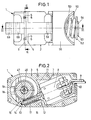
- Fig. 2
- einen Querschnitt durch die Motor-Getriebe-Einheit gemäß der Schnittlinie II-II in Fig. 3,
- Fig. 3
- einen Querschnitt durch die Motor-Getriebe-Einheit gemäß der Schnittlinie III-III in Fig. 1,
- Fig. 4
- eine Längsansicht eines Abtriebs-Hohlrades,
- Fig. 5
- eine Stirnansicht des Abtriebs-Hohlrades entsprechend dem Sichtpfeil V in Fig. 4, und
- Fig. 6
- eine Draufsicht auf eine Widerlager-Ringscheibe.
- Fig. 1
- 2 shows a side view of a motor-transmission unit in accordance with the arrows I in FIGS. 2 and 3,
- Fig. 2
- 3 shows a cross section through the motor-gear unit according to the section line II-II in FIG. 3,
- Fig. 3
- 2 shows a cross section through the motor / gear unit according to section line III-III in FIG. 1,
- Fig. 4
- a longitudinal view of an output ring gear,
- Fig. 5
- an end view of the output ring gear according to the arrow V in Fig. 4, and
- Fig. 6
- a plan view of an abutment washer.
Die in der Zeichnung dargestellte Motor-Getriebe-Einheit weist ein aus
einem Gehäuseunterteil 1 und einem Gehäuseoberteil 2 bestehendes, aus
einem schweißfähigen thermoplastischen Kunststoff gebildetes Gehäuse auf,
wobei die beiden Gehäuseteile mit aneinanderlegbaren Flanschen 3, 4 versehen
sind. Der dem Gehäuseunterteil 1 zugewandte Flansch 3 ist mit Zentrierlöchern
5 versehen, während am Flansch 4 des Gehäuseoberteils 2
diesen Zentrierlöchern 5 zugeordnete Zapfen 6 ausgebildet sind, die in
die Zentrierlöcher 5 eingeführt und nach der Montage und dem Zusammenstekken
des Gehäuseunterteils 1 und des Gehäuseoberteils 2 verschweißt
werden, so daß sie gleichzeitig auch zur festen Verbindung von Gehäuseunterteil
1 und Gehäuseoberteil 2 dienen.The motor-transmission unit shown in the drawing has one
an existing
Das Gehäuse 1, 2 ist mit einem Aufnahmeraum 7 für einen Elektromotor 8
versehen, dessen elektrische Versorgungs-Leitungen 9 durch eine Öffnung
10 in den Aufnahmeraum 7 geführt werden. Der Motor 8 ist drehrichtungsumkehrbar,
also in beiden möglichen Drehrichtungen antreibbar.Der Elektromotor
8 liegt im Aufnahmeraum 7 gegen im Gehäuse ausgebildete Anschläge
11 an, ist also mit dem Einlegen in das Gehäuseunterteil 1 bereits
in seiner Lage ausgerichtet.The
Der Elektromotor 8 ist mit einer aus dem Gehäuse 1, 2 frei vorragenden
Welle 12 versehen, deren vom Elektromotor 8 entferntes freies Ende 13 in
einer im Gehäuseunterteil 1 ausgeformten Lagerschale 14 abgestützt ist.
Auf der aus Stahl bestehenden Welle 12 ist eine aus Kunststoff bestehende
Zylinder-Schnecke 15 eines Schneckengetriebes 16 gegenüber der Welle 12
undrehbar, beispielsweise durch Preßsitz, angebracht.The
Die schraubenförmige Verzahnung 17 der Schnecke 15 greift in eine entsprechend
angepaßte Verzahnung 18 eines Schneckenrades 19 ein, das zusammen
mit der Schnecke 15 das Schneckengetriebe 16 bildet. The
Dem Schneckengetriebe 16 ist ein Planetengetriebe 20 nachgeordnet. Das
Planetengetriebe 20 weist ein einstückig mit dem Schneckenrad 19 ausgebildetes,
mit diesem also drehfest verbundenes Sonnenrad 21 auf, in dessen
Außen-Verzahnung 22 drei Planetenräder 23, von denen nur eines
dargestellt ist, mit ihrer entsprechenden Außen-Verzahnungen 24 eingreifen.
Außerdem stützen die Planetenräder 23 sich an einem Hohlrad 25 ab,
das mit einer Innen-Verzahnung 26 versehen ist, in die die jeweilige
Außen-Verzahnung 24 der Planetenräder 23 eingreift. Das Hohlrad 25 ist
gegenüber dem Gehäuse 1, 2 undrehbar, wozu es mit Vorsprüngen 27 an
seinem Außenumfang versehen ist, die in angepaßte Ausnehmungen 28 im
Gehäuse 1, 2 eingreifen. Die Planetenräder 23 sind auf Lagerzapfen 29
eines Steg-Unterteils 30 drehbar gelagert und werden dadurch in gleichen
Winkelabständen zueinander gehalten.A
Die Planetenräder 23 sind jeweils einstückig mit einem Zahnrad 32 eines
Hohlrad-Getriebes 33 ausgebildet. Die Außenverzahnung dieser Zahnräder
32 des Hohlrad-Getriebes 33 greifen in eine Innen-Verzahnung 35 eines
Abtriebs-Hohlrades 36 des Hohlrad-Getriebes 33 ein. In die Zahnräder 32
greift jeweils ein Lagerzapfen 37 eines Steg-Oberteils 38 ein. Das Steg-Unterteil
30 und das Steg-Oberteil 38 sind mittels am Steg-Unterteil 30
ausgebildeter Aufnahmeöffnungen 39 und in diese eingreifende, am Steg-Oberteil
38 ausgebildeter Verbindungszapfen 40 miteinander zu einem gehäuseartigen
Steg miteinander verbunden.The planet gears 23 are each in one piece with a
Das Abtriebs-Hohlrad 36 weist einen einstückig mit diesem ausgebildeten
zylindischen Lagerabschnitt 41 auf, der radial zur gemeinsamen Drehachse
42 des Schneckenrades 19, des Planetengetriebes 20 und des Hohlrad-Getriebes
33 in einer Lagerschale 43 gelagert ist, die am Gehäuseoberteil 3
ausgebildet ist. Das Abtriebs-Hohlrad 36 ist weiter in Richtung der Drehachse
42 relativ zum Gehäuseoberteil 2 durch sich radial zur Drehachse
42 erstreckende Anschlagflächen 44, 45 festgelegt, die die Drehung des
Abtriebs-Hohlrades 36 nicht behindern, aber das Spiel, d.h. die Verschiebbarkeit
des Hohlrades 36 in Richtung der Drehachse 42, auf etwa
0,1 mm beschränken. The
Das Schneckengetriebe 16, das Planetengetriebe 20 und das Hohlradgetriebe
33 bilden ein Untersetzungsgetriebe.The
Das Schneckenrad 19 ist auf einer durchgehenden zylindrischen Achse 46
aus Stahl gelagert, deren eines Ende in einer Aufnahme 47 im Gehäuseunterteil
1 mit Preßsitz, also gegenüber dem Gehäuseunterteil 1 undrehbar,
gehalten ist. Das andere Ende der Achse 46 ist in einer zur Drehachse 42
konzentrischen, zylindrischen Ausnehmung 48 des Abtriebs-Hohlrades 36
radial zur Drehachse 42 weitgegehend spielfrei abgestützt, wobei aber die
undrehbare Achse 46 die Drehung des Abtriebs-Hohlrades 46 nicht behindert.
Das Schneckenrad 19 ist auf der Achse 46 frei drehbar gelagert und
in Richtung der Drehachse 42 gegen die Stirnseite 49 der Aufnahme 47 in
Richtung zum Gehäuseunterteil 1 abgestützt. In Richtung zum Abtriebs-Hohlrad
36 ist es axial am Hohlrad 25 des Planetengetriebes 20 abgestützt.The
Das insgesamt aus Metall, beispielsweise Zink-Guß, bestehende Abtriebs-Hohlrad
36 weist einen sich an den Lagerabschnitt 41 anschließenden, im
wesentlichen zylindrischen Abtriebsabschnitt 50 auf, der mindestens eine,
bevorzugt aber zwei einander diametral zur Drehachse 42 gegenüberliegende
parallel zur Drehachse 42 verlaufende Längsnuten 51 aufweist. Auf dem
Abtriebs-Abschnitt 50 ist ein Reibring 52 einer Rutschkupplung 53 angeordnet,
der mit je einem Vorsprung 54 in die Längsnuten 51 eingreift,
wodurch eine drehfeste Verbindung zwischen dem Abtriebs-Hohlrad 36 und
dem Reibring 52 hergestellt wird. Der Reibring 52 liegt gegen einen Ringbund
55 am Übergang vom Lagerabschnitt 41 zum Abtriebsabschnitt 51 in
Richtung der Drehachse 42 fest an. Er bildet die oben bereits angesprochene
Anschlagfläche 45.The entire output ring gear made of metal, such as
Der Abtriebsabschnitt 50 ist von einem Abtriebs-Schwenkteil 56 umgeben,
das eine parallel zur Drehachse 42 verlaufende Ausnehmung 57 aufweist,
in die ein nicht dargestellter Bolzen eines zu verschwenkenden Teiles
eingreifen kann. Das Abtriebs-Schwenkteil 56 weist eine Reibfläche 58 auf,
die an einer Reibfläche 59 des Reibrings 52 anliegt. Beide Reibflächen 58,
59 sind kegelstumpfförmig ausgebildet und verjüngen sich vom Gehäuse-oberteil
2 weg unter einem halben Kegelöfinunpwhkel a. Es gilt 7° ≤
a ≤ 15° und bevorzugt a ≃ 10°.The
Das Abtriebs-Schwenkteil 56 wird mittels einer vorgespannten Schrauben-Druckfeder
60 in Richtung zum Reibring 52 gedrückt, wobei vom Schwenkteil
56 und dem Reibring 52 nur die Reibflächen 58, 59 aneinanderliegen.
Zwischen diesen beiden Teilen wird also die erwähnte Rutschkupplung 53
gebildet, deren Rutsch-Moment durch den Reibungskoeffizienten zwischen
der Reibfläche 59 des Reibrings 52 und der Reibfläche 58 des Schwenkteils
56 und durch die normal - also senkrecht - zu den Reibflächen 58, 59
wirkende Kraft und den mittleren Durchmesser d der Reibfläche 58, 59 bestimmt
wird. Die zwischen den Reibflächen 58, 59 senkrecht zu ihnen wirkende
Kraft ist bei einer vorgegebenen Kraft der Druckfeder 60 in Richtung
der Drehachse 42 umso größer, je kleiner der halbe Kegelöffnungswinkel
a der Reibflächen 58, 59 ist. Die senkrecht zu den Reibflächen 58,
59 zwischen diesen wirkenden Kraft ist auf auf jeden Fall um ein Mehrfaches
größer, also die Kraft der Druckfeder 60. Es kommt hinzu, daß der
Reibring 52 aus Metall, beispielsweise aus Zink-Guß, besteht, während
das Abtriebs-Schwenkteil 56 aus einem gängigen Kunststoff besteht.The
Die Schrauben-Druckfeder 60 liegt unter Zwischenschaltung einer als
Druckscheibe 61 dienenden Ringscheibe gegen das Abtriebs-Schwenkteil 56
an. Diese Druckscheibe 61 ist ebenfalls in den Längsnuten 51 mittels Vorsprüngen
54 drehfest zum Abtriebs-Hohlrad 36 festgelegt. Das zwischen der
Druckscheibe 61 und dem Schwenkteil 56 wirkende Reibmoment ist mindestens
um den Quotienten 10 kleiner als das Rutschmoment der Rutschkupplung
53.The
Die Druckfeder 60 liegt weiterhin im Bereich des freien Endes 64 des Abtriebsabschnitts
50 gegen eine weitere, als Widerlager 62 dienende Ringscheibe
an, die mit dem Abtriebsabschnitt 50 mittels eines Bajonettverschlusses
63 verriegelt ist. Die beiden Ringscheiben bestehen aus Metall,
beispielsweise Stahl. Sie sind identisch ausgebildet und weisen den
Längsnuten 51 angepaßte Vorsprünge 54 auf, die im Querschnitt identisch
den Vorsprüngen 54 am Reibring 52 sind. The
Wie aus den Fig. 4 bis 6 in Verbindung mit Fig. 3 hervorgeht, ist zur
Erzeugung des Bajonettverschlusses 63 im Bereich des freien Endes 64 des
Abtriebs-Hohlrades 36 an dessen Abtriebsabschnitt 50 jeweils eine Teil-Umfangsnut
65 ausgebildet, die einseitig aus einer Längsnut 51 herausführt.
Jede Teil-Umfangsnut 65 ist also an einem Ende 66 zu einer Längsnut
51 offen. Dagegen ist sie am anderen Ende 67 zu der jeweils anderen
Längsnut 51 verschlossen. Jede Teil-Umfangsnut 65 weist eine zum freien
Ende 64 hin gerichtete Ausnehmung 68 auf, die den Vorsprüngen 54 an
der Widerlager-Ringscheibe 62 entsprechen.As can be seen from FIGS. 4 to 6 in connection with FIG. 3, is for
Generation of the
Alle Zahnräder, mit Ausnahme des Abtriebs-Hohlrades 36, bestehen aus
Kunststoff und sind um die Drehachse 42 oder eine hierzu parallele Achse
drehbar.All gears, with the exception of the
Die Montage geht in der Weise vor sich, daß der Elektromotor 8 in den
Aufnahmeraum 7 im Gehäuseunterteil 1 eingelegt und die Leitungen 9
durch die Öffnung 10 herausgeführt werden. Das freie Ende 13 der bereits
mit der Schnecke 15 versehenen Welle 12 wird hierbei in die Lagerschale
14 eingesetzt. Zuvor oder nachher wird die Achse 46 in die Aufnahme 47
eingedrückt. Dann wird das Schneckenrad 19 des Planetengetriebes 20 auf
die Achse aufgeschoben, bis es zur Anlage an der Stirnseite 49 der Aufnahme
47 kommt. Im Anschluß daran wird das Hohlrad 25 des Planetengetriebes
20 auf die Achse geschoben. Dann wird die vormontierte Einheit
aus Steg-Unterteil 30, Planetenrädern 23 mit Zahnrädern 32 und Steg-Oberteil
38 derart in das Hohlrad 25 eingeschoben, daß die Außen-Verzahnungen
24 der Planetenräder 23 in Eingriff mit der Innen-Verzahnung 26
des Hohlrades 25 kommen. Danach wird das Abtriebs-Hohlrad auf die Achse
46 aufgeschoben, wobei gleichzeitig die Außen-Verzahnungen 34 der
Zahnräder 32 mit der Innen-Verzahnung 35 des Abtriebs-Hohlrades 36 in
Eingriff kommen. Außerdem wird die Achse 46 hierbei in der Ausnehmung
48 des Abtriebs-Hohlrades 36 aufgenommen und radial zur Drehachse 42
abgestützt. Im Anschluß daran wird das Gehäuse-Oberteil 2 auf das Gehäuse-Unterteil
1 aufgesetzt, wobei der Abtriebsabschnitt 50 durch die
Lagerschale 43 hindurchgeführt wird. Die Zapfen 6 des Gehäuse-Oberteils
2 greifen hierbei in die Zentrierlöcher 5 des Gehäuse-Unterteils 1 ein und
werden mit diesem, beispielsweise durch Ultraschall, verschweißt. Das
Abtriebs-Hohlrad 36 ist jetzt mit seinem Lagerabschnitt 41 in der Lager-schale
43 des Gehäuse-Oberteils 2 radial gelagert. Im Anschluß daran
wird der Reibring 52 der Rutsch-Kupplung 53 auf den Abtriebs-Abschnitt
50 aufgeschoben und dann das Abtriebs-Schwenkteil 56 aufgesetzt, so daß
die beiden Reibflächen 58, 59 aneinanderliegen. Dann wird die Druckscheibe
61 auf den Abtriebsabschnitt 50 aufgeschoben und die Schrauben-Druckfeder
60 ebenfalls auf den Abtriebs-Abschnitt 50 aufgesetzt. Mittels
der Widerlager-Ringscheibe 62 wird anschließend die Schrauben-Druckfeder
60 in Richtung zum Reibring 52 vorgespannt und die Widerlager-Ringscheibe
62 mittels des Bajonettverschlusses 63 mit dem Abtriebsanschnitt
50 verriegelt. Hierzu wird die Widerlager-Ringscheibe 62 unter Zusammendrücken
der Druckfeder 60 auf das freie Ende 64 des Abtriebsabschnitts
50 aufgeschoben und nach Erreichen der Teil-Umfangsnuten 65 derart verdreht,
daß die Vorsprünge 54 in diese Teil-Umfangsnuten 65 gelangen und
zwar bis zu deren Anschlag am verschlossenen Ende 67. Wenn jetzt die
Widerlager-Ringscheibe 62 entlastet wird, wird sie soweit in Richtung zum
freien Ende 64 zurückgeschoben, bis ihre Vorsprünge 54 in den Ausnehmungen
68 zur Anlage kommen. In diesen Ausnehmungen 68 ist dann die
Widerlager-Ringscheibe 62 gegenüber dem Abtriebsabschnitt 50 unverdrehbar,
kann also nicht lediglich durch Drehen gelöst werden, und zwar
unabhängig davon, in welcher Richtung der Abtriebsabschnitt 50 mit dem
Abtriebs-Schwenkteil 56 um die Drehachse 42 verdreht wird.The assembly proceeds in such a way that the
Die fertig montierte Motor-Getriebe-Einheit kann mittels am Gehäuse 1, 2
ausgebildeter Befestigungsöffnungen 69 für einen entsprechenden Einsatz
montiert werden. Ein solcher Einsatz erfolgt beispielsweise in Außenspiegeln
von Kraftfahrzegen und zwar insbesondere in Außenspiegeln für
Lastkraftwagen vorgesehen.The fully assembled motor-gear unit can be attached to the
Claims (6)
- A drive unit comprisingcharacterizeda) a housing which includes a first piece (1) and a second piece (2);b) a worm gear (16) which hasa worm (15) drivable by an electric motor (8), anda worm wheel (19) mounted in the first piece (1) for rotation around a turning axis (42);c) a planetary drive (20) which is coupled with the worm wheel (19) in driving connection concentrically of the turning axis (42); andd) an output gear (50, 41, 36) which is mounted in the second piece (2) and coupled with the planetary drive (20) in driving connection and disposed concentrically of the turning axis (42);e) a substantially cylindrical axle (46) being provided, the first end of which is mounted in the first piece (1) and the second end of which in the output gear (50, 41, 36) in each case radially of the turning axis (42); andf) the worm wheel (19) being mounted freely rotatably on the axle (46);g) in that the first end of the axle (46) is press fit in a sleeve-type recess (47) of the first piece (1) axially and radially of the turning axis (42);h) in that the output gear (50, 41, 36), seen in the axial direction, is formed by an element (36) of the planetary drive (20), by a cylindrical section (41) and an output gear section (50); andi) in that the second end of the axle (46) is mounted in the cylindrical section (41) which is supported in a bearing shell (43) of the second piece (2) radially of the turning axis (42).
- A drive unit according to claim 1, characterized in that the axle (46) consists of metal, in particular of steel.
- A drive unit according to one of claims 1 or 2, characterized in that the second end of the axle (46) is mounted in a recess (48) of the cylindrical section (41).
- A drive unit according to one of claims 1 to 3, characterized in that the element (36) of the planetary drive is non-displaceably mounted on the bearing shell (43) in the direction of the turning axis (42).
- A drive unit according to one of claims 1 to 4, characterized in that the element (36) of the planetary drive is formed as an annular output gear (36) of an annular gear drive (33) which is coupled with the planetary drive (20) in driving connection.
- A drive unit according to one of claims 1 to 5, characterized in that the worm (15) is fixed on a shaft (12), the free end (13) of which that faces away from an electric motor (8) is supported in a bearing shell (14) of the first piece (1).
Applications Claiming Priority (2)
| Application Number | Priority Date | Filing Date | Title |
|---|---|---|---|
| DE19615007A DE19615007A1 (en) | 1996-04-16 | 1996-04-16 | Gear unit |
| DE19615007 | 1996-04-16 |
Publications (3)
| Publication Number | Publication Date |
|---|---|
| EP0802348A2 EP0802348A2 (en) | 1997-10-22 |
| EP0802348A3 EP0802348A3 (en) | 1998-04-29 |
| EP0802348B1 true EP0802348B1 (en) | 2001-02-28 |
Family
ID=7791429
Family Applications (1)
| Application Number | Title | Priority Date | Filing Date |
|---|---|---|---|
| EP97104375A Expired - Lifetime EP0802348B1 (en) | 1996-04-16 | 1997-03-14 | Transmission unit |
Country Status (4)
| Country | Link |
|---|---|
| US (1) | US6007446A (en) |
| EP (1) | EP0802348B1 (en) |
| DE (2) | DE19615007A1 (en) |
| MX (1) | MX9702766A (en) |
Families Citing this family (15)
| Publication number | Priority date | Publication date | Assignee | Title |
|---|---|---|---|---|
| DE29904028U1 (en) | 1999-03-05 | 1999-09-02 | Klann Tools Ltd | Safety spindle head for spindle drives |
| DE20105791U1 (en) | 2001-04-03 | 2002-08-14 | MEKRA Lang GmbH & Co. KG, 90765 Fürth | Mirror arrangement for motor vehicles |
| DE10148611B4 (en) | 2001-10-02 | 2005-01-27 | Mekra Lang Gmbh & Co. Kg | Device for the pivotable mounting of a support arm for an outside mirror |
| GB0204820D0 (en) * | 2002-03-01 | 2002-04-17 | Standen John P | Gear mechanism for use in controlling vehicle rear-view mirrors and measuring angular deflection of an articulated trailer relative to the tractor |
| US20050054471A1 (en) * | 2003-09-08 | 2005-03-10 | Yakov Fleytman | Drive axle assembly and differential |
| JP2005091826A (en) * | 2003-09-18 | 2005-04-07 | Fuji Xerox Co Ltd | Image forming apparatus, driving mechanism for image forming apparatus and manufacturing method of worm gear set |
| DE10346403B4 (en) * | 2003-10-07 | 2007-05-10 | Pierburg Gmbh | locking device |
| KR20150110655A (en) * | 2013-02-22 | 2015-10-02 | 마그나 파워트레인 아게 운트 코 카게 | Gearbox housing and method for producing a gearbox housing |
| WO2014205217A1 (en) * | 2013-06-19 | 2014-12-24 | Magna International Inc. | Sealed actuator with internal clutching |
| CN106103163B (en) | 2014-03-21 | 2019-11-01 | 麦格纳国际公司 | Extensible aerodynamics carriage cover system |
| EP3636519A1 (en) | 2014-03-21 | 2020-04-15 | Magna International Inc. | Deployable aerodynamic side panel system |
| CN106536334B (en) | 2014-06-11 | 2019-08-16 | 麦格纳外饰公司 | Active front deflector |
| CN110194224B (en) | 2014-06-11 | 2021-12-03 | 麦格纳外饰公司 | Active front deflector |
| JP6618415B2 (en) * | 2016-04-08 | 2019-12-11 | 株式会社東海理化電機製作所 | Vehicle visual recognition device |
| DE102017129186B4 (en) * | 2017-12-07 | 2021-07-01 | Motherson Innovations Company Limited | Rearview device for a motor vehicle, assembly method therefor and motor vehicle with a rearview device |
Family Cites Families (24)
| Publication number | Priority date | Publication date | Assignee | Title |
|---|---|---|---|---|
| DE7627888U1 (en) * | 1900-01-01 | Julius Bauser Kg, Kontrolluhrenfabrik, 7241 Empfingen | ||
| US3265362A (en) * | 1964-03-02 | 1966-08-09 | Warren E Moody | Hoisting devices |
| JPS6047130B2 (en) * | 1975-08-14 | 1985-10-19 | 市光工業株式会社 | Chestnut dual-use rear view mirror |
| US4133344A (en) * | 1976-06-10 | 1979-01-09 | The Toro Company | Power transmission for self-propelled irrigation system |
| DE2820541C2 (en) * | 1978-05-11 | 1986-10-09 | Bernhard Dipl.-Wirtsch.-Ing. 3002 Wedemark Mittelhäuser | Exterior rearview mirrors for automobiles |
| DE2846586A1 (en) * | 1978-10-26 | 1980-05-08 | Kienzle Uhrenfabriken Gmbh | Remote adjustment vehicle outer rear mirror - has two servomotors and epicyclic reduction gears and slip clutches for connection to two cranks |
| DE3013009A1 (en) * | 1980-04-03 | 1981-10-08 | Gustav Magenwirth Gmbh & Co, 7432 Urach | Servo driven wing mirror with limited slip - has ball bearing coupling with axial sprung races |
| DE3434905A1 (en) * | 1984-09-22 | 1986-04-03 | SWF Auto-Electric GmbH, 7120 Bietigheim-Bissingen | DRIVE UNIT, ESPECIALLY FOR ADJUSTING WINDOW WINDOWS, SLIDING ROOFS, SEATS AND SIMILAR MOTOR VEHICLE PARTS |
| DE3669464D1 (en) * | 1985-05-21 | 1990-04-19 | Aisin Seiki | ANGLE ADJUSTMENT DEVICE. |
| US4641887A (en) * | 1985-09-16 | 1987-02-10 | Keiper Recaro Incorporated | Planetary seat back adjuster |
| DE3741615A1 (en) * | 1987-12-09 | 1989-06-22 | Reitter & Schefenacker Kg | Electric motor drive for window lifters of motor vehicles |
| US4921083A (en) * | 1989-02-28 | 1990-05-01 | Square D Company | Clutch module with predetermined torque |
| DE3914334C2 (en) * | 1989-04-29 | 1994-08-04 | Kienzle Uhrenfabriken Gmbh | Adjustment device for a vehicle exterior mirror |
| NL8902300A (en) * | 1989-09-14 | 1991-04-02 | Iku Holding Montfoort Bv | FLIP-UP MECHANISM FOR A REAR VIEW MIRROR FOR A VEHICLE. |
| JP2515645Y2 (en) * | 1989-11-21 | 1996-10-30 | アスモ 株式会社 | Motor with reduction gear |
| IT220513Z2 (en) * | 1990-05-15 | 1993-09-24 | Gilardini Spa | REAR-VIEW MIRROR FOR A VEHICLE. |
| JPH0463738A (en) * | 1990-07-04 | 1992-02-28 | Ichikoh Ind Ltd | Electric stay retractable mirror device |
| DE4119748C2 (en) * | 1991-06-15 | 1994-06-09 | Luchtenberg Gmbh & Co | Folding rear-view mirror |
| IT1252140B (en) * | 1991-11-29 | 1995-06-05 | Commer Spa | DEVICE FOR THE CONTROLLED ROTATION OF AN EXTERNAL REAR-VIEW MIRROR |
| JPH05222245A (en) * | 1992-02-10 | 1993-08-31 | Tokai Carbon Co Ltd | Rubber composition |
| NL9202266A (en) * | 1992-12-24 | 1994-07-18 | Iku Holding Montfoort Bv | Mirror folding mechanism, and vehicle provided with such a mirror folding mechanism. |
| DE4311355C2 (en) * | 1993-04-06 | 1995-01-26 | Stephan Werke Gmbh & Co | Worm gear |
| JPH07195979A (en) * | 1993-12-28 | 1995-08-01 | Sakae Riken Kogyo Kk | Electric folding type mirror |
| JP3323686B2 (en) * | 1995-01-10 | 2002-09-09 | アスモ株式会社 | Moving object position detection device |
-
1996
- 1996-04-16 DE DE19615007A patent/DE19615007A1/en not_active Withdrawn
-
1997
- 1997-03-14 DE DE59703027T patent/DE59703027D1/en not_active Expired - Lifetime
- 1997-03-14 EP EP97104375A patent/EP0802348B1/en not_active Expired - Lifetime
- 1997-04-04 US US08/832,926 patent/US6007446A/en not_active Expired - Lifetime
- 1997-04-16 MX MX9702766A patent/MX9702766A/en unknown
Also Published As
| Publication number | Publication date |
|---|---|
| EP0802348A3 (en) | 1998-04-29 |
| EP0802348A2 (en) | 1997-10-22 |
| DE19615007A1 (en) | 1997-10-23 |
| DE59703027D1 (en) | 2001-04-05 |
| US6007446A (en) | 1999-12-28 |
| MX9702766A (en) | 1998-04-30 |
Similar Documents
| Publication | Publication Date | Title |
|---|---|---|
| DE69919135T2 (en) | STARTER FOR MOTOR VEHICLE WITH GEARBOX WITH TORSION DAMPING FORMATS | |
| DE3006331C3 (en) | transmission | |
| DE3430067C1 (en) | PTO shaft | |
| EP0802348B1 (en) | Transmission unit | |
| DE3830283C2 (en) | ||
| DE2912104C2 (en) | Fastening device between the drive shaft and the gear of a gear pump | |
| DE102011075183A1 (en) | Adjusting drive for an adjusting device of a motor vehicle seat | |
| DE3732811A1 (en) | TORQUE TRANSMISSION DEVICE FOR A VEHICLE WITH FOUR-WHEEL DRIVE | |
| EP1989096B1 (en) | Helical bevel gear for a rack-and-pinion steering system | |
| DE19547980A1 (en) | Differential drive with rotary housing and crosspiece | |
| DE102004008538B4 (en) | Differential with a bolt mounting assembly | |
| EP0802084A1 (en) | Transmission unit | |
| DE3713870A1 (en) | UNIVERSAL JOINT | |
| DE4302726C2 (en) | Toothed shaft connection and method for producing a toothed shaft connection | |
| DE69822008T2 (en) | Transmission clutch unit | |
| DE2259985A1 (en) | ARRANGEMENT FOR DETACHABLE ATTACHING A HUB OR A WHEEL ON A SHAFT | |
| DE4424988C1 (en) | Hydrodynamic torque converter with lock=up clutch | |
| DE102016104150A1 (en) | steering gear | |
| DE2613656C2 (en) | Drive arrangement for commercial vehicles with all-wheel drive | |
| EP1101964A1 (en) | Overload coupling | |
| DE68912134T2 (en) | BEARING PIN LOCK WITH CAM EFFECT FOR A DIFFERENTIAL. | |
| EP0491221B1 (en) | Torque transmitting connection joint, especially for demi-axles or multiple-part cardan propeller shafts | |
| EP2640623B1 (en) | Roller-mounted rack and pinion drive | |
| DE102017118571A1 (en) | angle gear | |
| DE4217123C2 (en) | Backrest for vehicle seats, in particular motor vehicle seats |
Legal Events
| Date | Code | Title | Description |
|---|---|---|---|
| PUAI | Public reference made under article 153(3) epc to a published international application that has entered the european phase |
Free format text: ORIGINAL CODE: 0009012 |
|
| AK | Designated contracting states |
Kind code of ref document: A2 Designated state(s): DE ES FR GB IT SE |
|
| PUAL | Search report despatched |
Free format text: ORIGINAL CODE: 0009013 |
|
| AK | Designated contracting states |
Kind code of ref document: A3 Designated state(s): DE ES FR GB IT SE |
|
| 17P | Request for examination filed |
Effective date: 19980818 |
|
| 17Q | First examination report despatched |
Effective date: 20000222 |
|
| GRAG | Despatch of communication of intention to grant |
Free format text: ORIGINAL CODE: EPIDOS AGRA |
|
| GRAG | Despatch of communication of intention to grant |
Free format text: ORIGINAL CODE: EPIDOS AGRA |
|
| GRAG | Despatch of communication of intention to grant |
Free format text: ORIGINAL CODE: EPIDOS AGRA |
|
| GRAG | Despatch of communication of intention to grant |
Free format text: ORIGINAL CODE: EPIDOS AGRA |
|
| GRAH | Despatch of communication of intention to grant a patent |
Free format text: ORIGINAL CODE: EPIDOS IGRA |
|
| GRAH | Despatch of communication of intention to grant a patent |
Free format text: ORIGINAL CODE: EPIDOS IGRA |
|
| GRAA | (expected) grant |
Free format text: ORIGINAL CODE: 0009210 |
|
| AK | Designated contracting states |
Kind code of ref document: B1 Designated state(s): DE ES FR GB IT SE |
|
| PG25 | Lapsed in a contracting state [announced via postgrant information from national office to epo] |
Ref country code: SE Free format text: THE PATENT HAS BEEN ANNULLED BY A DECISION OF A NATIONAL AUTHORITY Effective date: 20010228 Ref country code: IT Free format text: LAPSE BECAUSE OF FAILURE TO SUBMIT A TRANSLATION OF THE DESCRIPTION OR TO PAY THE FEE WITHIN THE PRE;WARNING: LAPSES OF ITALIAN PATENTS WITH EFFECTIVE DATE BEFORE 2007 MAY HAVE OCCURRED AT ANY TIME BEFORE 2007. THE CORRECT EFFECTIVE DATE MAY BE DIFFERENT FROM THE ONE RECORDED.SCRIBED TIME-LIMIT Effective date: 20010228 Ref country code: GB Free format text: LAPSE BECAUSE OF FAILURE TO SUBMIT A TRANSLATION OF THE DESCRIPTION OR TO PAY THE FEE WITHIN THE PRESCRIBED TIME-LIMIT Effective date: 20010228 Ref country code: FR Free format text: LAPSE BECAUSE OF FAILURE TO SUBMIT A TRANSLATION OF THE DESCRIPTION OR TO PAY THE FEE WITHIN THE PRESCRIBED TIME-LIMIT Effective date: 20010228 Ref country code: ES Free format text: THE PATENT HAS BEEN ANNULLED BY A DECISION OF A NATIONAL AUTHORITY Effective date: 20010228 |
|
| REF | Corresponds to: |
Ref document number: 59703027 Country of ref document: DE Date of ref document: 20010405 |
|
| EN | Fr: translation not filed | ||
| GBV | Gb: ep patent (uk) treated as always having been void in accordance with gb section 77(7)/1977 [no translation filed] |
Effective date: 20010228 |
|
| PLBE | No opposition filed within time limit |
Free format text: ORIGINAL CODE: 0009261 |
|
| STAA | Information on the status of an ep patent application or granted ep patent |
Free format text: STATUS: NO OPPOSITION FILED WITHIN TIME LIMIT |
|
| 26N | No opposition filed | ||
| PGFP | Annual fee paid to national office [announced via postgrant information from national office to epo] |
Ref country code: DE Payment date: 20160520 Year of fee payment: 20 |
|
| REG | Reference to a national code |
Ref country code: DE Ref legal event code: R071 Ref document number: 59703027 Country of ref document: DE |