EP0799933B1 - Kalander für Papier o. dgl. - Google Patents
Kalander für Papier o. dgl. Download PDFInfo
- Publication number
- EP0799933B1 EP0799933B1 EP97104117A EP97104117A EP0799933B1 EP 0799933 B1 EP0799933 B1 EP 0799933B1 EP 97104117 A EP97104117 A EP 97104117A EP 97104117 A EP97104117 A EP 97104117A EP 0799933 B1 EP0799933 B1 EP 0799933B1
- Authority
- EP
- European Patent Office
- Prior art keywords
- calender according
- control
- zones
- calender
- elements
- Prior art date
- Legal status (The legal status is an assumption and is not a legal conclusion. Google has not performed a legal analysis and makes no representation as to the accuracy of the status listed.)
- Expired - Lifetime
Links
Images
Classifications
-
- D—TEXTILES; PAPER
- D21—PAPER-MAKING; PRODUCTION OF CELLULOSE
- D21G—CALENDERS; ACCESSORIES FOR PAPER-MAKING MACHINES
- D21G1/00—Calenders; Smoothing apparatus
- D21G1/02—Rolls; Their bearings
- D21G1/0253—Heating or cooling the rolls; Regulating the temperature
- D21G1/0286—Regulating the axial or circumferential temperature profile of the roll
-
- D—TEXTILES; PAPER
- D21—PAPER-MAKING; PRODUCTION OF CELLULOSE
- D21G—CALENDERS; ACCESSORIES FOR PAPER-MAKING MACHINES
- D21G1/00—Calenders; Smoothing apparatus
-
- D—TEXTILES; PAPER
- D21—PAPER-MAKING; PRODUCTION OF CELLULOSE
- D21G—CALENDERS; ACCESSORIES FOR PAPER-MAKING MACHINES
- D21G1/00—Calenders; Smoothing apparatus
- D21G1/002—Opening or closing mechanisms; Regulating the pressure
- D21G1/004—Regulating the pressure
Definitions
- the invention relates to a calender for paper or the like with at least two treatment centers that to be traversed one after the other by a path, whereby each treatment site in a direction transverse to the web direction extending row in a given Pitching zones arranged next to each other for influencing of the web material.
- roller devices include with which paper, cardboard, foil and similar material in terms of thickness, gloss, smoothness and other properties can be refined. It embraces hence both compact and super calenders, the "soft” Have working columns on one side through a hard roller and on the other side limited a roller provided with an elastic cover are, as well as smoothing, their working column are bounded on both sides by hard rollers.
- a calender of the type described at the outset is, for example from the brochure "The new generation of soft calenders" (Print date 11/94 d) known to the applicant.
- the paper web is separated by two working columns headed, each between a hard roller and one roller with elastic cover are formed.
- the elastic roller is a bending adjustment roller with a large number of actuators arranged side by side in the form of support elements, due to their Pressurizing the roller shell against the driven one press hard roller.
- the invention is therefore based on the object a way a calender of the type described above to demonstrate how while maintaining the constructive Effort, the correction potential can be increased.
- This object is achieved in that the positioning zones opposite the second treatment center the positioning zones of the first treatment site by one Fraction of the division are offset.
- Adjustment zones each by a single individually adjustable Actuator formed. This leads to extreme narrow individually controllable areas.
- two identical bending adjustment rollers are a multitude of zones of two Support elements as well as a single support element at one edge exhibit. This enables one Reserve roller get by, what space and cost can save.
- Actuators also come instead of the support elements mentioned of another type, especially inductive acting heating elements or heating or cooling air nozzles. It also applies to these actuators that they have a certain one Must have minimum width and only through the invention proposal suitable for correcting narrower areas are.
- the treatment sites are separated at two arranged roller pairs or stacks provided are. Here the treatment sites are complete separated from each other, which is the control of each Actuators relieved.
- Another control intervention is preferably thereby possible that the one bend adjustment roller opposite the other bending adjustment roller for the purpose of cross profile control is axially displaceable.
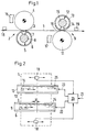
- Fig. 1 is a calender for finishing a paper web 1 shown.
- a first treatment site 2 is formed by a soft working gap 3, the of a driven hard roller 4 and a soft one Roller 5 is limited.
- the latter is a bending adjustment roller, whose roll shell 6 by actuators 7 in the Form of hydrostatic support elements on a carrier 8 is supported.
- the jacket 6 consists of a fiber-reinforced Plastic.
- a second treatment site 9 is formed by the soft working gap 10, the by a driven hard roller 11 and a soft one Roller 12 is limited.
- the soft roller is again a bend adjustment roller, the fiber-reinforced Plastic existing jacket 13 by actuators 14 in the form of hydrostatic support elements a rotatably arranged carrier 15 is supported.
- each treatment center 2 and 9 is an inductive one Heater 16 and 17 assigned to the also from a row arranged side by side Actuators exist. Instead of the inductive heating device can also use a range of cooling or hot air nozzles be provided.
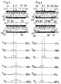
- a second sensor 19 is located behind the second Treatment site 9. These sensors measure certain Parameters of the web 1, for example the thickness, the Shine or smoothness.
- the measurement signals become a controller 20 fed to an input 21 for a cross-section setpoint owns.
- the two indicated schematically Outputs 22 and 23 have the actuators 7 and 14 individually a pressure with which they oppose the jacket 6 or 13 are pressed. In the drawing only eight actuators 7 and 14 are illustrated. In practice, however, it is a much larger one Number, with widths of 15 to 30 cm are common.
- There each actuator with its own pressure line 24 or 25 is provided, there are relatively small Z1 or Z2 setting zones.
- FIG. 3 illustrates how the situation is with the prior art.
- reference numbers are increased by 100 used. They are identical Rollers 105 and 112, each with two actuators 107 or 114 to a jointly controllable control zone Z3 and Z4 are combined.
- each roller has a plurality of adjustment zones Z5 and Z6, which are each formed by two actuators 207 and 214, and at the edge each have a shorter zone Z7 and Z8, which is formed by only one actuator 207a and 214a.
- the positioning zones are offset by half a division. If you want to make a correction in the area of arrow C, it is sufficient to apply pressure to the actuating zone Z5.
- the action curve P 203 is then identical to the desired total action curve P C.
- the roller 12 can be compared to the roller 5 in a simple manner Be offset in that the calender frame, in which the roller 12 is mounted, laterally offset is. There is also a possibility to change the size of the Change offset in operation in order to create a to be able to introduce additional control parameters.
Landscapes
- Paper (AREA)
- Casting Or Compression Moulding Of Plastics Or The Like (AREA)
- Folding Of Thin Sheet-Like Materials, Special Discharging Devices, And Others (AREA)
Description
- Fig. 1
- eine vereinfachte Seitenansicht eines Kalanders, an dem die Erfindung ausgebildet sein kann,
- Fig. 2
- eine schematische Darstellung des Kalanders der Fig. 1,
- Fig. 3
- eine schematische Darstellung eines bekannten Kalanders und die von einzelnen Stellzonen erzielbare Streckenlast und
- Fig. 4
- eine schematische Darstellung einer zweiten Ausführungsform eines erfindungsgemäßen Kalanders und die von einzelnen Stellzonen erzielbare Streckenlast.
Claims (12)
- Kalander für Papier o.dgl. mit mindestens zwei Behandlungsstellen, die nacheinander von einer Bahn durchlaufen werden, wobei jede Behandlungsstelle in einer quer zur Bahnlaufrichtung sich erstreckenden Reihe in einer vorgegebenen Teilung nebeneinander angeordnete Stellzonen zur Beeinflussung des Bahnmaterials aufweist, dadurch gekennzeichnet, daß die Stellzonen (Z2; Z6) der zweiten Behandlungsstelle (9) gegenüber den Stellzonen (Z1; Z5) der ersten Behandlungsstelle (2) um einen Bruchteil der Teilung versetzt sind.
- Kalander nach Anspruch 1, dadurch gekennzeichnet, daß die Stellzonen (Z1, Z2; Z5, Z6) der ersten und der zweiten Behandlungsstelle (2, 9) um eine halbe Teilung gegeneinander versetzt sind.
- Kalander nach Anspruch 1 oder 2, dadurch gekennzeichnet, daß die Stellzonen (Z1, Z2) jeweils durch ein einzelnes individuell einstellbares Stellglied (7, 14) gebildet sind.
- Kalander nach Anspruch 1 oder 2, dadurch gekennzeichnet, daß die Stellzonen (Z5, Z6) durch jeweils zwei oder mehr gemeinsam verstellbaren Stellglieder (207, 214) gebildet sind.
- Kalander nach einem der Ansprüche 1 bis 4, dadurch gekennzeichnet, daß die Behandlungsstellen (2, 9) durch Arbeitsspalte (3, 10; 203, 210) gebildet sind, die jeweils durch zwei Walzen (4, 5; 11, 12; 204, 205; 211, 212) begrenzt sind und daß die eine Walze eine Biegeeinstellwalze ist, deren Mantel (6, 13; 206, 213) durch die Stellglieder (7; 14; 207, 214) bildende, mit einstellbarem Druck beaufschlagbare Stützelemente gegen die andere Walze preßbar ist.
- Kalander nach Anspruch 5, dadurch gekennzeichnet, daß zur Bildung der beiden Arbeitsspalte (3, 10, 203, 210) zwei gleiche Biegeeinstellwalzen (5, 12; 205, 212) vorgesehen sind, die eine Vielzahl von Stellzonen (Z1, Z2; Z5, Z6) aus je zwei Stützelementen sowie an einem Rand ein einzelnes Stützelement aufweisen (Fig. 4).
- Kalander nach Anspruch 5, dadurch gekennzeichnet, daß zur Bildung der beiden Arbeitsspalte (3, 10) zwei gleiche Biegeeinstellwalzen (5, 12) mit gleichmäßig verteilten Stützelementen vorgesehen sind und daß die die Biegewalzen tragenden Gestelle gegeneinander versetzt sind (Fig. 2).
- Kalander nach einem der Ansprüche 5 bis 7, dadurch gekennzeichnet, daß der Mantel (6, 13; 206, 213) der Biegeeinstellwalze (5, 12; 205, 212) im wesentlichen aus faserverstärktem Kunststoff besteht.
- Kalander nach einem der Ansprüche 1 bis 8, dadurch gekennzeichnet, daß die Stellglieder (16, 17) durch induktiv wirkende Heizelemente gebildet sind.
- Kalander nach einem der Ansprüche 1 bis 9, dadurch gekennzeichnet, daß die Stellglieder (16, 17) durch Heiz- oder Kühlluftdüsen gebildet sind.
- Kalander nach einem der Ansprüche 1 bis 10, dadurch gekennzeichnet, daß die Behandlungsstellen (2, 9) an zwei getrennt angeordneten Walzenpaaren oder -stapeln vorgesehen sind.
- Kalander nach einem der Ansprüche 1 bis 11, dadurch gekennzeichnet, daß die eine Biegeeinstellwalze (12) gegenüber der anderen Biegeeinstellwalze (5) zum Zweck der Querprofilregelung axial verschiebbar ist.
Applications Claiming Priority (2)
| Application Number | Priority Date | Filing Date | Title |
|---|---|---|---|
| DE19613878 | 1996-04-06 | ||
| DE19613878A DE19613878C1 (de) | 1996-04-06 | 1996-04-06 | Kalander für Papier o. dgl. |
Publications (2)
| Publication Number | Publication Date |
|---|---|
| EP0799933A1 EP0799933A1 (de) | 1997-10-08 |
| EP0799933B1 true EP0799933B1 (de) | 1999-09-22 |
Family
ID=7790705
Family Applications (1)
| Application Number | Title | Priority Date | Filing Date |
|---|---|---|---|
| EP97104117A Expired - Lifetime EP0799933B1 (de) | 1996-04-06 | 1997-03-12 | Kalander für Papier o. dgl. |
Country Status (5)
| Country | Link |
|---|---|
| US (1) | US6024838A (de) |
| EP (1) | EP0799933B1 (de) |
| JP (1) | JP2887123B2 (de) |
| CA (1) | CA2201663C (de) |
| DE (2) | DE19613878C1 (de) |
Families Citing this family (4)
| Publication number | Priority date | Publication date | Assignee | Title |
|---|---|---|---|---|
| FI115144B (fi) | 1999-10-13 | 2005-03-15 | Metso Paper Inc | Kalanterointimenetelmä |
| EP1470289B1 (de) * | 2002-01-29 | 2011-07-13 | Metso Paper, Inc. | Kalander zur verarbeitung einer gegebenenfalls beschichteten faserstoffbahn |
| FI114648B (fi) * | 2003-06-18 | 2004-11-30 | Metso Paper Inc | Menetelmä ja laitteisto paperi- tai kartonkirainan kalanteroimiseksi |
| FI120269B (fi) | 2006-12-18 | 2009-08-31 | Metso Paper Inc | Kuiturainaa käsittelevän koneen telajärjestely |
Family Cites Families (12)
| Publication number | Priority date | Publication date | Assignee | Title |
|---|---|---|---|---|
| DE3408119A1 (de) * | 1984-02-06 | 1985-08-14 | Sulzer-Escher Wyss GmbH, 7980 Ravensburg | Nasspresse zum entwaessern einer faserbahn |
| DE3408118A1 (de) * | 1984-02-06 | 1985-08-14 | Sulzer-Escher Wyss GmbH, 7980 Ravensburg | Nasspresse zum entwaessern einer faserbahn |
| GB2161105B (en) * | 1984-07-04 | 1988-06-15 | Fred Whitehead | Calendar or roll assembly |
| CA1249470A (en) * | 1985-01-08 | 1989-01-31 | Gregory L. Wedel | Electromagnetic extended nip press |
| FI77489C (fi) * | 1985-11-27 | 1989-03-10 | Valmet Oy | Pressvals foer behandling av i synnerhet en pappersbana eller motsvarande. |
| CH670217A5 (de) * | 1986-06-20 | 1989-05-31 | Escher Wyss Gmbh | |
| DE3920204A1 (de) * | 1988-10-31 | 1990-05-10 | Escher Wyss Gmbh | Verfahren zum glaetten einer papier- oder kartonbahn |
| US4945654A (en) * | 1989-04-20 | 1990-08-07 | Mason Robert J H | Application of superheated steam |
| JP2879393B2 (ja) * | 1992-07-13 | 1999-04-05 | ハウス食品株式会社 | キャップの良否検出装置 |
| US5439559A (en) * | 1994-02-14 | 1995-08-08 | Beloit Technologies | Heavy-weight high-temperature pressing apparatus |
| DE4442746C1 (de) * | 1994-12-01 | 1996-05-02 | Voith Sulzer Finishing Gmbh | Verfahren und Vorrichtung zum Behandeln einer Materialbahn |
| DE19645407A1 (de) * | 1996-11-04 | 1998-05-07 | Voith Sulzer Papiermasch Gmbh | Schuhpresse |
-
1996
- 1996-04-06 DE DE19613878A patent/DE19613878C1/de not_active Expired - Fee Related
-
1997
- 1997-03-12 DE DE59700458T patent/DE59700458D1/de not_active Expired - Lifetime
- 1997-03-12 EP EP97104117A patent/EP0799933B1/de not_active Expired - Lifetime
- 1997-03-28 US US08/825,346 patent/US6024838A/en not_active Expired - Fee Related
- 1997-04-03 CA CA002201663A patent/CA2201663C/en not_active Expired - Fee Related
- 1997-04-03 JP JP9084771A patent/JP2887123B2/ja not_active Expired - Lifetime
Also Published As
| Publication number | Publication date |
|---|---|
| US6024838A (en) | 2000-02-15 |
| DE19613878C1 (de) | 1997-06-12 |
| DE59700458D1 (de) | 1999-10-28 |
| CA2201663C (en) | 1999-12-14 |
| CA2201663A1 (en) | 1997-10-06 |
| JP2887123B2 (ja) | 1999-04-26 |
| JPH1025689A (ja) | 1998-01-27 |
| EP0799933A1 (de) | 1997-10-08 |
Similar Documents
| Publication | Publication Date | Title |
|---|---|---|
| DE3516535C2 (de) | ||
| EP0732446B1 (de) | Kalander für die zweiseitige Behandlung einer Papierbahn | |
| DE19511145C2 (de) | Kalander für die zweiseitige Papierbehandlung | |
| DE3020669C2 (de) | Verfahren zur Steuerung der Liniendruckverteilung in einem Kalander sowie ensprechender Kalander | |
| DE3201635C2 (de) | Kalanderanordnung | |
| EP0732445B2 (de) | Kalander für die Behandlung einer Papierbahn | |
| EP0715019A2 (de) | Verfahren und Vorrichtung zum Behandeln einer Materialbahn | |
| EP0732447B1 (de) | Kalander für die zweiseitige Behandlung einer Papierbahn | |
| EP0799933B1 (de) | Kalander für Papier o. dgl. | |
| EP0744492A1 (de) | Kalander | |
| EP0748895A2 (de) | Kalander | |
| DE4345345C2 (de) | Walze | |
| DE19508349C2 (de) | Kalander für die Behandlung einer Papierbahn und Verfahren zu dessen Betrieb | |
| EP0732443B2 (de) | Kalander für die Behandlung einer Papierbahn | |
| DE69608515T2 (de) | Verfahren zur Regulierung der Lastverteilung einer Durchbiegungseinstellwalze und Durchbiegungseinstellwalze | |
| DE19534911C2 (de) | Kalander für die Behandlung einer Papierbahn | |
| EP0933472A2 (de) | Verfahren zum Betrieb eines Kalanders und Kalander | |
| DE19800331A1 (de) | Papierkalander und Verfahren zu dessen Betrieb | |
| DE4026774A1 (de) | Mehrwalzen-glaettwerk | |
| EP0792965A1 (de) | Verfahren zum Satinieren von Papier und Kalander zur Durchführung des Verfahrens | |
| DE102013200614A1 (de) | Vorrichtung und Verfahren zur Kalandrierung einer Faserbahn | |
| DE102007047904A1 (de) | Walzenanordnung einer Faserstoffbahn-Behandlungsmaschine | |
| DE9421548U1 (de) | Walzenmaschine zur Behandlung einer Papierbahn | |
| DE9321073U1 (de) | Walze | |
| DE8803310U1 (de) | Lagereinrichtung |
Legal Events
| Date | Code | Title | Description |
|---|---|---|---|
| PUAI | Public reference made under article 153(3) epc to a published international application that has entered the european phase |
Free format text: ORIGINAL CODE: 0009012 |
|
| 17P | Request for examination filed |
Effective date: 19970718 |
|
| AK | Designated contracting states |
Kind code of ref document: A1 Designated state(s): DE FI FR GB |
|
| GRAG | Despatch of communication of intention to grant |
Free format text: ORIGINAL CODE: EPIDOS AGRA |
|
| GRAG | Despatch of communication of intention to grant |
Free format text: ORIGINAL CODE: EPIDOS AGRA |
|
| GRAH | Despatch of communication of intention to grant a patent |
Free format text: ORIGINAL CODE: EPIDOS IGRA |
|
| 17Q | First examination report despatched |
Effective date: 19990310 |
|
| GRAH | Despatch of communication of intention to grant a patent |
Free format text: ORIGINAL CODE: EPIDOS IGRA |
|
| GRAA | (expected) grant |
Free format text: ORIGINAL CODE: 0009210 |
|
| AK | Designated contracting states |
Kind code of ref document: B1 Designated state(s): DE FI FR GB |
|
| GBT | Gb: translation of ep patent filed (gb section 77(6)(a)/1977) |
Effective date: 19990923 |
|
| REF | Corresponds to: |
Ref document number: 59700458 Country of ref document: DE Date of ref document: 19991028 |
|
| ET | Fr: translation filed | ||
| PGFP | Annual fee paid to national office [announced via postgrant information from national office to epo] |
Ref country code: FR Payment date: 20000316 Year of fee payment: 4 |
|
| PLBE | No opposition filed within time limit |
Free format text: ORIGINAL CODE: 0009261 |
|
| STAA | Information on the status of an ep patent application or granted ep patent |
Free format text: STATUS: NO OPPOSITION FILED WITHIN TIME LIMIT |
|
| 26N | No opposition filed | ||
| PG25 | Lapsed in a contracting state [announced via postgrant information from national office to epo] |
Ref country code: GB Free format text: LAPSE BECAUSE OF NON-PAYMENT OF DUE FEES Effective date: 20010312 |
|
| GBPC | Gb: european patent ceased through non-payment of renewal fee |
Effective date: 20010312 |
|
| PG25 | Lapsed in a contracting state [announced via postgrant information from national office to epo] |
Ref country code: FR Free format text: LAPSE BECAUSE OF NON-PAYMENT OF DUE FEES Effective date: 20011130 |
|
| REG | Reference to a national code |
Ref country code: FR Ref legal event code: ST |
|
| PGFP | Annual fee paid to national office [announced via postgrant information from national office to epo] |
Ref country code: FI Payment date: 20110314 Year of fee payment: 15 |
|
| PGFP | Annual fee paid to national office [announced via postgrant information from national office to epo] |
Ref country code: DE Payment date: 20110325 Year of fee payment: 15 |
|
| PG25 | Lapsed in a contracting state [announced via postgrant information from national office to epo] |
Ref country code: FI Free format text: LAPSE BECAUSE OF NON-PAYMENT OF DUE FEES Effective date: 20120312 |
|
| REG | Reference to a national code |
Ref country code: DE Ref legal event code: R119 Ref document number: 59700458 Country of ref document: DE Effective date: 20121002 |
|
| PG25 | Lapsed in a contracting state [announced via postgrant information from national office to epo] |
Ref country code: DE Free format text: LAPSE BECAUSE OF NON-PAYMENT OF DUE FEES Effective date: 20121002 |