EP0798616A2 - Verfahren zur Erzeugung diskreter Punkte, die einen Schneideweg definieren, der für einen Rohling gewählte Fertigungsbedingungen erfüllt - Google Patents
Verfahren zur Erzeugung diskreter Punkte, die einen Schneideweg definieren, der für einen Rohling gewählte Fertigungsbedingungen erfüllt Download PDFInfo
- Publication number
- EP0798616A2 EP0798616A2 EP97105264A EP97105264A EP0798616A2 EP 0798616 A2 EP0798616 A2 EP 0798616A2 EP 97105264 A EP97105264 A EP 97105264A EP 97105264 A EP97105264 A EP 97105264A EP 0798616 A2 EP0798616 A2 EP 0798616A2
- Authority
- EP
- European Patent Office
- Prior art keywords
- cutter
- discrete
- discrete points
- interval
- workpiece
- Prior art date
- Legal status (The legal status is an assumption and is not a legal conclusion. Google has not performed a legal analysis and makes no representation as to the accuracy of the status listed.)
- Granted
Links
Images


Classifications
-
- G—PHYSICS
- G05—CONTROLLING; REGULATING
- G05B—CONTROL OR REGULATING SYSTEMS IN GENERAL; FUNCTIONAL ELEMENTS OF SUCH SYSTEMS; MONITORING OR TESTING ARRANGEMENTS FOR SUCH SYSTEMS OR ELEMENTS
- G05B19/00—Programme-control systems
- G05B19/02—Programme-control systems electric
- G05B19/18—Numerical control [NC], i.e. automatically operating machines, in particular machine tools, e.g. in a manufacturing environment, so as to execute positioning, movement or co-ordinated operations by means of programme data in numerical form
- G05B19/4097—Numerical control [NC], i.e. automatically operating machines, in particular machine tools, e.g. in a manufacturing environment, so as to execute positioning, movement or co-ordinated operations by means of programme data in numerical form characterised by using design data to control NC machines, e.g. CAD/CAM
-
- B—PERFORMING OPERATIONS; TRANSPORTING
- B23—MACHINE TOOLS; METAL-WORKING NOT OTHERWISE PROVIDED FOR
- B23Q—DETAILS, COMPONENTS, OR ACCESSORIES FOR MACHINE TOOLS, e.g. ARRANGEMENTS FOR COPYING OR CONTROLLING; MACHINE TOOLS IN GENERAL CHARACTERISED BY THE CONSTRUCTION OF PARTICULAR DETAILS OR COMPONENTS; COMBINATIONS OR ASSOCIATIONS OF METAL-WORKING MACHINES, NOT DIRECTED TO A PARTICULAR RESULT
- B23Q15/00—Automatic control or regulation of feed movement, cutting velocity or position of tool or work
- B23Q15/20—Automatic control or regulation of feed movement, cutting velocity or position of tool or work before or after the tool acts upon the workpiece
- B23Q15/22—Control or regulation of position of tool or workpiece
-
- G—PHYSICS
- G05—CONTROLLING; REGULATING
- G05B—CONTROL OR REGULATING SYSTEMS IN GENERAL; FUNCTIONAL ELEMENTS OF SUCH SYSTEMS; MONITORING OR TESTING ARRANGEMENTS FOR SUCH SYSTEMS OR ELEMENTS
- G05B2219/00—Program-control systems
- G05B2219/30—Nc systems
- G05B2219/35—Nc in input of data, input till input file format
- G05B2219/35216—Program, generate nc program, code from cad data
-
- G—PHYSICS
- G05—CONTROLLING; REGULATING
- G05B—CONTROL OR REGULATING SYSTEMS IN GENERAL; FUNCTIONAL ELEMENTS OF SUCH SYSTEMS; MONITORING OR TESTING ARRANGEMENTS FOR SUCH SYSTEMS OR ELEMENTS
- G05B2219/00—Program-control systems
- G05B2219/30—Nc systems
- G05B2219/35—Nc in input of data, input till input file format
- G05B2219/35221—Generate cutter path as function of speed, acceleration condition selected by operator
-
- Y—GENERAL TAGGING OF NEW TECHNOLOGICAL DEVELOPMENTS; GENERAL TAGGING OF CROSS-SECTIONAL TECHNOLOGIES SPANNING OVER SEVERAL SECTIONS OF THE IPC; TECHNICAL SUBJECTS COVERED BY FORMER USPC CROSS-REFERENCE ART COLLECTIONS [XRACs] AND DIGESTS
- Y02—TECHNOLOGIES OR APPLICATIONS FOR MITIGATION OR ADAPTATION AGAINST CLIMATE CHANGE
- Y02P—CLIMATE CHANGE MITIGATION TECHNOLOGIES IN THE PRODUCTION OR PROCESSING OF GOODS
- Y02P90/00—Enabling technologies with a potential contribution to greenhouse gas [GHG] emissions mitigation
- Y02P90/02—Total factory control, e.g. smart factories, flexible manufacturing systems [FMS] or integrated manufacturing systems [IMS]
Definitions
- the present invention relates in general to a process of generating cutter path data representative of a succession of discrete points which generally define a cutter path to be followed by a cutting tool or cutter for machining a workpiece. More particularly, the invention is concerned with improvements in the process of determining such discrete cutter path definition points.
- a manufacture of a desired part or product by machining a workpiece on an NC (numerically controlled) machine tool includes a CAD (computer aided design) data processing step, a CAM (computer aided manufacturing) data processing step, and an NC machining step, which are implemented in the order of description, as illustrated in Fig. 17.
- part geometry data in the form of surface models and solid models which represent a desired cutting profile of the workpiece are generated according to commands generated by the operator of a CAD processor.
- successive discrete points generally defining a cutter path are obtained by calculation on the basis of the part geometry data received by a CAM processor, so that a predetermined reference point of the cutter is moved through those discrete points in the subsequent NC machining step.
- the reference point of the cutter may be a center point of the cutter, for example.
- the cutter path defined by the discrete points (hereinafter referred to as "discrete cutter path definition points") is offset from the desired cutting profile of the workpiece by a distance determined by the cutter configuration, in the direction away from the desired cutting profile. For instance, the offset distance of the cutter path is determined by the radius of the cutter.
- cutter path data representative of the discrete cutter path definition points are then generated.
- the CAM data processing step further includes a post-processing operation to convert the cutter path data to NC data (numerical control data) suitable for use in the subsequent NC machining step in which the workpiece is machined into the desired part.
- NC data include cutter path data representative of the discrete cutter path definition points, and interpolation data indicative of either linear interpolation or circular interpolation of the adjacent discrete cutter path definition data.
- linear interpolation the adjacent discrete points are connected by a straight segment.
- the adjacent discrete points are connected by a circular arc segment.
- the NC data are received by a numerical control device, which applies cutter motion commands to the numerically controlled or NC machine tool, so that the NC machine tool is operated to move the cutter along the cutter path according to the cutter motion commands, for thereby machining the workpiece to produce the part having the desired shape.
- the series of steps to manufacture the desired part includes a data processing operation for generating the discrete cutter path definition points generally defining the path to be taken by the cutter.
- This data processing operation is implemented after the part geometry data are prepared and before the cutter motion commands are generated.
- the data processing operation in question is the operation to obtain the discrete cutter path definition points by calculation in the CAM data processing step.
- the discrete cutter path definition points are determined on the basis of nominal profile or geometry of the part (desired cutting profile of the workpiece), and a predetermined tolerance which is a permissible maximum amount of deviation of the cutter path generally defined by the succession of discrete points, from a nominal cutter path which exactly follows the nominal part profile, as indicated in Fig. 19.
- the cutter path generally defined by the discrete points consists of straight segments which connect the adjacent discrete points. That is, the cutter path is approximated by the discrete points, so as to minimize the required volume of the cutter path data while assuring a minimum sufficient degree of NC machining accuracy of the workpiece (dimensional accuracy of the part manufactured).
- the tolerance used in determining the discrete cutting path definition points is made relatively small, the requirement for reducing the volume of the cutter path data may be satisfied while assuring a satisfactory degree of the NC machining accuracy.
- there are other requirements in the manufacture of a part by NC machining such as a requirement for increased machining efficiency while assuring the satisfactory NC machining accuracy.
- a research conducted by the inventors of the present invention has indicated an importance of taking into account conditions associated with movement velocities of the cutter, even in the step of generating or determining the discrete cutter path definition points which are subsequently processed into the NC data used in the NC machining step.
- the conventional CAM data processing technique does not allow the operator to take into account the conditions other than the tolerance indicated above, such as the conditions associated with the movement velocities of the cutter.
- the conventional technique suffers from drawbacks arising from the incapability to satisfy the above requirements in the NC machining.
- the object may be achieved according to a first aspect of this invention, which provides a process of generating a succession of discrete points to be followed by a cutter during movements of the cutter to machine a workpiece, comprising: (a) a step of operating a computer including a data processor, to select at least one of a plurality of different discrete point generating conditions stored in a memory of the computer, according to a command entered by an operator of the computer, each of the different discrete point generating conditions including at least one requirement that should be satisfied when the discrete points are generated so as to define a cutter path; (b) a step of operating the computer to calculate an interval of the discrete points in the direction of the succession, according to the selected at least one of the discrete point generating conditions; and (c) a step of operating the computer to generate the discrete points on the basis of the calculated interval, such that the discrete points are spaced apart from each other by the interval in the direction of the succession.
- the operator of the computer selects a desired one or more of the different discrete point generating conditions stored in the memory, and the computer generates a succession of discrete points which generally define a cutter path along which the cutter is moved. Since the different discrete point generating conditions correspond different requirements or needs in machining the workpiece to manufacture a desired part, the present process permits the workpiece to be machined so as to satisfy the desired requirements or needs.
- the plurality of different discrete point generating conditions may include respective cutter-velocity-related requirements which are associated with movement velocities of the cutter during machining of the workpiece and which are different from each other.
- a second aspect of the invention provides a process of generating a succession of discrete points to be followed by a cutter during movements of the cutter to machine a workpiece, comprising: (a) a step of calculating an interval of said discrete points in the direction of said succession, so as to meet at least one cutter-velocity-related requirement associated with movement velocities of said cutter during machining of the workpiece; and (b) a step of generating said discrete points on the basis of the calculated interval, such that said discrete points are spaced apart from each other by said interval in the direction of said succession.
- the discrete points defining the cutter path are generated, taking into account the cutter-velocity-related requirement or requirements which relate to the movement velocities of the cutter.
- the requirement or requirements associated with the movement velocities of the cutter during machining of the workpiece is/are taken into account in the process of determining the discrete points defining the cutter path, prior to the machining process.
- the cutter-velocity-related requirements are taken into account only in the process of machining of the workpiece. Accordingly, the present process permits increased versatility to meet various requirements relating to the machining of the workpiece.
- the term "movement velocities of the cutter” is interpreted to mean not only the velocities of feeding movements of the cutter (i.e., speeds at which a reference of the cutter is moved relative to the workpiece), but also the rotating speed of the cutter about its axis.
- the cutter-velocity-related requirements may include a predetermined upper limit of a resultant movement velocity of the cutter, and a predetermined upper limit of a variation of a movement velocity of the cutter along each controllable axis, for example. These upper limits are associated with the velocities.
- the cutter-velocity-related requirements may further include a predetermined upper limit of centrifugal acceleration of the cutter, and predetermined upper limits of acceleration in the direction of the succession of the discrete points.
- interval of the discrete points is generally interpreted to mean a length of straight segments of a bent cutter path defined by the discrete points, but may be interpreted to mean a length of curved segments of a nominal cutter path on which the discrete points are located.
- the process further comprises a step of generating curve defining functional equations representative of curves which define a nominal cutter path, on the basis of a geometry of a part to be manufactured by machining of the workpiece.
- the discrete points are generated on the basis of the generated functional equations and the interval of the discrete points.
- the discrete points can be generated on the basis of the desired part geometry and the selected discrete point generating condition or conditions or the cutter-velocity-related requirement or requirements. If the generated discrete points are found to be inadequate, the process should be repeated to generate adequate discrete points.
- the curve defining functional equations representative of the curved segments of the nominal cutter path are first obtained on the basis of the part geometry, and then the discrete points are generated on the basis of the obtained functional equations. If the discrete points originally generated on the basis of the functional equations are found inadequate, adequate discrete points may be generated by merely changing an appropriate variable or variables in the functional equations. In other words, the use of the same functional equations permits easy correction of the inadequate discrete points or addition of discrete points.
- the functional equations represent the nominal cutter path which exactly follows the desired part geometry, all of the discrete points generated lie on the nominal cutter path.
- the present form of the invention is particularly effective for moving the cutter along a curved path, since the curved segments of the nominal cutter path are represented by the respective functional equations.
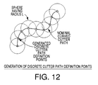
- the interval of the discrete points is usually defined as the length of each straight segment of a bent cutter path defined by the discrete points.
- two adjacent discrete points are determined to be located at two points of intersection between the nominal cutter path (curved path) and a sphere which has a radius equal to the interval of the discrete points and the center of which is located on the nominal cutter path.
- the thus determined two discrete points are located on the nominal cutter path and are spaced apart from each other by the interval.
- the nominal cutter path does not necessarily lie on the same plane. The concept of determining the two intersection points of the sphere and the nominal cutter path as the two adjacent discrete points permits the generation of the discrete points even where the nominal cutter path does not lie on the same plane.
- the discrete points may also be generated by projecting the nominal cutter path in a direction which is almost perpendicular to the cutter path, and obtaining intersection points between this projection of the nominal cutter path and a circle which has a radius equal to the interval of the discrete points. Any one of the above-indicated methods of determining the intersection points as the adjacent discrete points permits the generation of the discrete points on the nominal cutter path (curved path).
- the step of generating the discrete points may include a step of positioning a sphere or a circle having a radius equal to the calculated interval of the discrete points, such that the center of the sphere or circle is located on the nominal cutter path represented by the functional equations, and determining each of at least one of two points of intersection between the nominal cutter path and the sphere or circle, as the next discrete point.
- the successive discrete points may be generated by moving the center of the sphere or circle along the nominal cutter path, from the last one of the already generated discrete points by the distance equal to the interval.
- the first preferred form of the first or second aspect of the invention permits easy regeneration of the discrete points, and assures a comparatively high degree of freedom in determining the discrete points, and a comparatively high degree of accuracy of the cutter path defined by the generated discrete points, with respect to the nominal cutter path.
- the cutter-velocity-related requirements or at least one cutter-velocity-related requirement include or includes a requirement that an acceleration of the cutter during machining of the workpiece by the cutter be held lower than a predetermined upper limit.
- the interval of the discrete points is calculated on the basis of said upper limit.
- the interval of the discrete points so as to prevent excessive acceleration and deceleration of the cutter.
- the cutter is fed along a curved path having a comparatively small radius of curvature, for example, it is desirable to reduce the interval of the discrete points, for reducing the angle of change of the cutter path direction, namely, for reducing the angle between the adjacent two straight segments of the cutter path defined by the discrete points, and for preventing excessive centrifugal acceleration of the cutter.
- the cutter is fed along a curved path having a comparatively large radius of curvature, it is desirable to increase the interval, and prevent excessive acceleration of the cutter in the direction of the succession of the discrete points.
- the second preferred form of the present process is adapted to calculate the interval of the discrete points on the basis of the upper limit of the acceleration of the cutter, which is one of the cutter-velocity-related requirements.
- the process further comprises a step of calculating an upper limit V ARmax of a resultant movement velocity of the cutter, on the basis of a radius R of curvature of a nominal path of the cutter and the upper limit G Amax of the centrifugal acceleration G A of the cutter.
- the interval L is calculated on the basis of the upper limit V ARmax and a time interval T at which motion commands to feed the cutter are supplied to a machine tool.
- the upper limit V ARmax of the resultant movement velocity of the cutter may be calculated as ⁇ R x ⁇ G Amax , and the interval L may be calculated as V ARmax x T.
- the second preferred form of the present process is adapted to determine the discrete points by taking into account the acceleration of the cutter, so that the machining efficiency can be easily improved.
- the above second preferred form of the process may include the feature of the first preferred form of the process described above.
- the cutter-velocity-related requirements or at least one cutter-velocity-related requirement include or includes predetermined upper limits of variations in feed rates of the cutter during feeding movements thereof along respective controllable axes.
- Each of the variations is an amount of change in the feed rate of the cutter along a corresponding one of the controllable axes, between two successive motions of the cutter which correspond respective two motion commands that are successively supplied to a machine tool at a predetermined time interval.
- the interval of the discrete points is calculated on the basis of the upper limits of the variations.
- the cutter of a machine tool for machining the workpiece is fed under the control of motion commands that are successively supplied to the machine tool at a predetermined time interval.
- motion commands that are successively supplied to the machine tool at a predetermined time interval.
- the third preferred form of the present process is adapted to calculate the interval of the discrete points on the basis of the upper limits of the variations in the feed rates of the cutter for the respective controllable axes, which upper limits are used as the cutter-velocity-related requirements.
- the above third preferred form of the present process may further comprise a step of calculating an upper limit V ARmax of a resultant movement velocity V AR of the cutter, on the basis of a radius R of curvature of the nominal path of the cutter and a predetermined upper limit G Amax of a centrifugal acceleration G A of the cutter.
- the step of generating the discrete points comprises a step of calculating an upper limit ⁇ max of an angle of change of direction of the cutter path defined by the discrete points, by dividing the upper limit ⁇ V Amax of the variation of the feed rate along each controllable axis by the upper limit V ARmax of the resultant movement velocity V AR , and a step of calculating the interval L of the discrete points by multiplying the upper limit ⁇ max by the radius R of curvature of the nominal path.
- the upper limit V ARmax may be calculated as ⁇ (R) x ⁇ (G Amax ), and the upper limit ⁇ max may be calculated as sin -1 ( ⁇ V Amax /V ARmax ) . Further, the interval L may be calculated as 2 x R x sin( ⁇ max /2) .
- the variation in the feed rate of the cutter between two successive motions of the cutter along each controllable axis is taken into account in determining the discrete points, so as to improve the machining efficiency.
- the above third preferred form of the process may include the feature of the first preferred form of the process described above.
- the cutter-velocity-related requirements or at least one cutter-velocity-related requirement include or includes a predetermined upper limit of a resultant movement velocity of the cutter during movements of the cutter along controllable axes of a machine tool to machine the workpiece.
- the interval of the discrete points is calculated on the basis of the upper limit of the resultant movement velocity and a time interval at which motion commands to feed the cutter along the controllable axes are supplied to the machine tool.
- the cutter is fed along the controllable axes according to the motion commands or pulses supplied to the machine tool at the predetermined time interval.
- a distance of movement of the cutter corresponding to one motion command can be determined by the time interval of the motion commands and the resultant movement velocity of the cutter.
- the interval of the discrete points to be followed by the cutter should correspond to the distance of movement of the cutter corresponding to one motion command.
- the fourth preferred form of the present process is adapted to calculate the interval of the discrete points on the basis of the time interval of the motion commands, and the upper limit of the resultant movement velocity of the cutter, which is one of the cutter-velocity-related requirements.
- the motions of the cutter caused by the motion commands are coincident with the time interval of the motion commands, whereby the cutter is less likely to be unnecessarily decelerated, advantageously resulting in an increase in the machining efficiency of the workpiece.
- This fourth preferred form of the process may include the features of the first preferred form of the process.
- the cutter-velocity-related requirements or at least one cutter-velocity-related requirement include or includes a predetermined upper limit of a resultant movement velocity of the cutter during movements of the cutter along controllable axes of a machine tool to machine the workpiece according to motion commands supplied to the machine tool at a predetermined time interval while the cutter is rotating about an axis thereof.
- the interval of the discrete points is calculated on the basis of the upper limit of the resultant movement velocity, and a commanded value of a rotating speed of the cutter, which commanded value is specified by an operator of the machine tool.
- the workpiece may be machined by a rotating cutter having at least one cutting blade or insert while the cutter is fed in a first direction to take a cutting pass along a predetermined path.
- the cutter is moved by a suitable in-feed distance in a second direction perpendicular to the first direction, and the cutter is fed again in the first direction to take a second cutting pass.
- the above-indicated in-feed distance determines the amount of stock removal from the workpiece in the second cutting pass.
- a plurality of cutting passes of the cutter are performed to remove the desired total amount of stock removal from the workpiece, to machine a desired portion of the workpiece which is covered by successive cutting regions corresponding to the cutting passes.
- Each cutting region corresponding to each cutting pass consists of unit cutting areas corresponding to respective motion commands.
- the length of the unit cutting areas in the first direction decreases with a decrease in the velocity of the feeding movement of the cutter in the first direction, and with an increase in the rotating speed of the cutter.
- the length of the unit cutting areas is generally considered to be proportional to VL/VR, where VL represents the feeding velocity VL of the cutter, while VR represents the rotating speed VR of the cutter.
- each cutting region corresponding to each cutting pass is substantially equal to the above-indicated in-feed distance in the second direction perpendicular to the first direction (feeding direction of the cutter).
- the fifth preferred form of the present process is adapted to take into account the upper limit of the resultant movement velocity of the cutter and the commanded rotating speed of the cutter, in determining the interval of the discrete points.
- the length of the unit cutting areas corresponding to the motion commands changes with the number N of the cutting blades of the cutter. That is, the length of the unit cutting areas decreases with an increase in the number N, when the feeding velocity VL and rotating speed VR are constant. For instance, an increase in the rotating speed VR of the cutter and an increase in the number N of the cutting blades of the cutter are equivalent to each other, in their effect on the length of the unit cutting areas. Therefore, it is possible to calculate the interval of the discrete points, on the basis of the number N of the cutting blades of the cutter, the commanded rotating speed S C and the predetermined upper limit V ARmax of the resultant movement velocity of the cutter.
- the interval L may be calculated as V ARmax /(S C x N) .
- the fifth preferred form of the present process is adapted to generate the discrete points so as to optimize the length of the unit cutting areas, namely, the distance of feeding movement corresponding to each motion command, whereby the surface finish of the machined workpiece can be easily improved, for example.
- the fifth preferred form of the process may include the features of the first preferred form of the process.
- the process according to the first and second aspects of this invention and the various preferred forms described above may use the upper limit V ARmax as one of the cutter-velocity-related requirements. If this upper limit V ARmax exceeds a commanded value V CR of the resultant movement velocity which is specified by the operator, the commanded value V CR may be set as the upper limit. Namely, the commanded value V CR entered by the operator may be used as the upper limit of the actual resultant movement velocity of the cutter, so that the interval of the discrete points is determined so as to prevent the actual resultant movement velocity V AR from exceeding the commanded value V CR .
- a method of machining a workpiece by a cutter movable on a machine tool comprising: (a) the process, according to the first or second aspect of the invention described above, of generating a succession of discrete points to be followed by the cutter during movements of the cutter to machine the workpiece; (b) a step of generating motion commands to move the cutter along the cutter path defined by the discrete points generated in the process; and (c) a step of controlling the machine tool to move the cutter according to the motion commands.
- a data storage medium for storing a program for executing the process according to the first or second aspect of the invention, such that the program is readable by a computer.
- the data storage medium may be a floppy disk, a magnetic tape, a magnetic disk, a magnetic drum, a magnetic card, an optical disk, a magneto-optical disk, a CD-ROM, or an IC card.
- a CAM processor receives part geometry data such as surface models or solid models, which have been generated in the CAD data processing step. Then, successive discrete cutter path definition points which generally define a cutter path are calculated on the basis of the received part geometry data, tolerance data and cutter geometry data.
- the tolerance data represent a tolerance of the accuracy to define the cutter path. Namely, the tolerance is a permissible maximum amount of deviation of the cutter path generally defined by the discrete points, from a nominal cutter path which exactly follows the nominal part profile.
- the cutter geometry data represent the geometry of the cutter, and include data representative of the radius of the cutter.
- the discrete cutter path definition points are offset or spaced apart from the desired cutting profile of the workpiece in the direction away from the cutting profile, by a distance determined by the radius of the tool. The distances between the adjacent discrete points are determined so that the deviation of the cutter path generally defined by the discrete points with respect to the nominal cutter path following the cutting profile of the workpiece (nominal part profile) is held within the tolerance indicated above. Then, cutter path data representative of the calculated discrete cutter path definition points are stored into a memory or data file of the CAM processor. The cutter path data are subjected to a post-processing operation, whereby NC data corresponding to the cutter path data are generated. The thus obtained NC data can be processed by a DNC (direct numerical control device) 10 shown in Fig. 17.
- DNC direct numerical control device
- the CAM data processing step is arranged as shown in Fig. 1.
- the part geometry data are received by a CAM processor.
- calculating operations are performed on the basis of the part geometry data and the cutter geometry data including data representative of the cutter radius, to obtain curve defining functional equations (hereinafter referred to as "curve defining equations") representative of curves which generally define a nominal cutter path along which the reference point (e.g., the center point) of the cutter is moved.
- curve defining equations representative of curves which generally define a nominal cutter path along which the reference point (e.g., the center point) of the cutter is moved.
- equation data representative of the curve defining equations are stored in a memory, and a succession of discrete cutter path definition points is generated on the basis of the equation data and according to one of a plurality of discrete point generating conditions which is selected by the operator.
- the discrete cutter path definition points generated lie on the curves represented by the curve defining equations.
- a NC machine tool 14 is controlled by a CNC (computerized numerical control device) 12, such that a cutter 16 and a workpiece 18 are moved relative to each other, to machine the workpiece 18 to produce the desired part.
- CNC computerized numerical control device
- the NC machine tool 14 has a plurality of controllable axes, and is adapted to receive from the CNC 12 motion commands or pulses at a predetermined time interval T for each of the controllable axes, so that the cutter 16 is moved along the controllable axes at controllable feed rates or velocities.
- an upper limit G Amax of an actual centrifugal acceleration of the cutter 16 during its movements there exist some restrictions including: (1) an upper limit G Amax of an actual centrifugal acceleration of the cutter 16 during its movements; and (2) upper limits ⁇ V AXmax , ⁇ V AYmax and ⁇ V AZmax of actual X-axis feed rate variation ⁇ V AX , actual Y-axis feed rate variation ⁇ V AY and actual Z-axis feed rate variation ⁇ V AZ , respectively.
- the variations ⁇ V AX , ⁇ V AY and ⁇ V AZ are variations in actual X-axis, Y-axis and Z-axis feed rates V AX , V AY and V AZ .
- the velocity of a resultant movement of the cutter 16 is specified by the operator. This velocity is referred to as “commanded resultant cutter movement velocity V CR ".
- the rotating speed of the cutter 16 about its axis is specified by the operator. This rotating speed is referred to as “commanded rotating speed S C ".
- the CAM data processing step is implemented by a CAM processor in the form of a CAM computer 20 as shown in Fig. 17.
- the computer 20 includes a data processor 22 such as a CPU (central processing unit), and a memory device 24 such as a read-only memory and a random-access memory.
- the computer 20 is connected to an external memory device 26 operable with a suitable data storage medium 28 such as a floppy disk.
- An appropriate program stored in the data storage medium 28 is read into the memory device 24 of the computer 20, and is temporarily stored in the memory device 24, so that the program is executed as needed by the data processor 22, to generate cutter path data representative of the discrete cutter path definition points, on the basis of the part geometry data, and to convert the cutter path data into the corresponding NC data.
- the part geometry data are received from a CAD computer 29.
- the CAM computer 20 is also connected to an input device 30 such as a keyboard with a mouse, through which the operator enters various commands into the CAM computer 20.
- An output device 32 such as a cathode ray tube (CRT), a liquid crystal display and a printer is connected to the CAM computer 20, so that data obtained during data processing by the computer 20 or as a result of the data processing are provided on the output device 32.
- CTR cathode ray tube
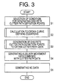
- a routine illustrated in the flow chart of Fig. 3 is executed by the data processor 22 of the CAM computer 20 according to the program stored in the memory device 24.
- step S1 in which one of a plurality of discrete point generating conditions is selected according to a command entered by the operator through the input device 30.
- the following three discrete point generating conditions are available and is selectable as needed.
- This first condition includes a restriction or requirement that the actual centrifugal acceleration G A of the cutter 16 during its movements under the control of the CNC 12 be held equal to or lower than the upper limit G Amax indicated above, and a restriction or requirement that the actual X-axis, Y-axis and Z-axis feed rate variations ⁇ V AX , ⁇ V AY and ⁇ V AZ be held equal to or smaller that the respective upper limits ⁇ V AXmax , ⁇ V AYmax and ⁇ V AZmax .
- the interval of the adjacent discrete cutter path definition points is determined so as to meet these restrictions or requirements.
- This first condition is usually selected when it is desired to operate the NC machine tool 14 so as to assure a relatively high machining efficiency.
- the interval between the adjacent discrete cutter path definition points is determined so that the cutter 16 is able to be moved in synchronization of the supply of the command pulses from the CNC 12 to the NC machine tool 12.
- the second condition is also selected when the relatively high machining efficiency is desired.
- this third condition is selected, the interval between the adjacent discrete cutter path definition points is determined so that the distance of movement of the cutter 16 per tooth under the control of the CNC 12 is held constant during the NC machining operation.
- This third condition is usually selected when it is desired to manufacture the desired part with a comparatively high degree of accuracy.
- the data storage medium 28 of the external memory device 26 also stores discrete point generating programs corresponding to the three conditions.
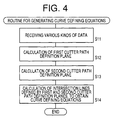
- Step S1 of the routine of Fig. 3 is followed by step S2 in which an equation generating program is read out from the external memory device 26 into the memory device 24 of the CAM computer 20, and is executed by the data processor 24, to generate the curve defining equations on the basis of the part geometry data and the cutter data described above.
- step S11 the CAM computer 20 receives various kinds of data such as the part geometry data and the cutter data including the cutter radius data.
- a first cutter path definition plane is calculated on the basis of the part geometry data and the cutter radius data.
- the first cutter path definition plane is offset by a distance determined by the radius of the cutter, from the desired cutting profile of the workpiece 18 represented by the part geometry data, in the direction away from the workpiece 18.
- a cutter path along which the cutter 16 is moved is defined as a line of intersection between two cutter path definition planes. One of these two planes is the first cutter path definition plane which is offset from the desired cutting profile of the workpiece 18, by the distance determined by the cutter radius, in the direction away from the desired cutting profile of the workpiece.
- Step S12 is followed by step S13 in which the other of the two cutter path definition planes, namely, the second cutter path definition plane is calculated on the basis of a command which is entered by the operator and which specifies a desired amount of stock removal from the workpiece 18 by one cutting pass of the cutter 16.
- This amount of stock removal is referred to as "in-feed increment”. Described more specifically, each of a plurality of flat or curved planes which are spaced apart from each other by a distance equal a predetermined in-feed increment of the cutter 16 is obtained as the second cutter path definition plane.
- step S14 the control flow goes to step S14 to obtain lines of intersection between the first cutter path definition plane and each of the second cutter path definition planes. These lines of intersection correspond to respective nominal cutter paths.
- Curve defining equations representative of these nominal cutter paths are obtained.
- the curve defining equations represent Bezier curves.
- a plurality of nominal cutter paths are indicated by arrow-headed lines in Fig. 8, by way of example.
- the second cutter path definition planes are curved planes.
- step S14 is formulated to obtain each of curve defining equations which represent respective curved segments that are connected to each other to define a nominal cutter path.
- the cutter paths correspond to respective cutting passes of the cutter 16 taken in the feeding direction indicated by the arrows. Each cutting pass is taken to remove the stock from the workpiece 18 by the predetermined amount corresponding to the in-feed increment. As the number of the cutting passes along the respective cutter paths increases, the total amount of stock removal from the workpiece 18 increases.
- step S2 to obtain the curve defining equations is followed by step S3 in which the discrete point generating program corresponding to the discrete point generating condition selected in step S1 is read out from the external memory device 26 into the memory device 24 of the CAM computer 20, and is executed by the data processor 22.
- step S3 the discrete cutter path definition points are generated for each nominal cutter path, as indicated in Fig. 9.
- a routine illustrated in the flow chart of Fig. 5 is executed according to the corresponding discrete point generating program.
- This routine of Fig. 5 is repeatedly executed for each of the curved segments of each nominal cutter path. This repetition also applies to the programs corresponding to the second and third discrete point generating conditions.
- the first curved segment of the nominal cutter path is processed.
- step S31 a minimum radius R MIN of curvature of the curved segment in question of the nominal cutter path is calculated on the basis of the corresponding curve defining equation.
- the minimum radius R MIN is the radius R of one of curved portions of the curved segment which has the smallest radius.
- the commanded value V CR is set as the upper limit V ARmax .
- step S33 the control flow goes to step S33 in which the CAM data computer 20 receives the upper limits ⁇ V AXmax , ⁇ V AYmax and ⁇ V AZmax of the variations ⁇ V AX , ⁇ V AY and ⁇ V AZ of the X-axis, Y-axis and Z-axis feed rates V AX , V AY and V AZ .
- Step S33 is followed by step S34 in which an upper limit ⁇ max of a change angle ⁇ of the cutter path direction is calculated for each axis, by dividing the upper limit ⁇ V AXmax , ⁇ V AYmax , ⁇ V AZmax by the upper limit V ARmax of the actual resultant cutter movement velocity V AR .
- the change angle ⁇ is an angle by which the direction of the cutter path is changed from one direction to another.
- the cutter path direction change angle ⁇ is smaller than the upper limit ⁇ max , the feed rate variations ⁇ V AX , ⁇ V AY and ⁇ V AZ will not exceed the respective upper limits ⁇ V AXmax , ⁇ V AYmax and ⁇ V AZmax .
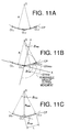
- the cutter 16 is actually moved along a bent cutter path consisting of straight segments defined by three discrete cutter path definition points CL1, CL2 and CL3, as indicated in Fig. 11A, at a velocity equal to the upper limit V ARmax of the actual resultant cutter movement velocity V AR .
- the bent cutter path deviates from a nominal circular arc cutter path CP having a radius R.
- the nominal cutter path CP lies on the X-Y plane, and is positioned such that the straight segment CL1-CL2 is aligned with the X axis, as indicated in Fig. 11B.
- the variation ⁇ V AX of the X-axis feed rate V AX of the cutter 16 be equal to or smaller than the upper limit ⁇ V AXmax , in order to assure a substantially constant A-axis movement velocity of the cutter 16.
- the variation ⁇ V AX is an amount of change of the X-axis feed rate V AX between the two successive incremental feeding motions corresponding to the respective two successive motion commands.
- the first motion takes place between the discrete points CL1 and CL2, and the second or last motion takes place between the discrete points CL2 and CL3. Therefore, the actual X-axis feed rate V AX during the second motion from CL2 to CL3 satisfies the following condition: V ARmax - ⁇ V AXmax ⁇ V AX ⁇ V ARmax + ⁇ V AXmax
- the variation ⁇ V AY of the Y-axis feed rate V AY should be smaller than the upper limit ⁇ V AYmax , and the actual Y-axis feed rate V AY during the second motion from CL2 to CL3 satisfies the following condition: - ⁇ V AYmax ⁇ V AY ⁇ ⁇ V AYmax
- the position of the discrete point CL3 to which the cutter 16 is moved according to the second motion command is determined to satisfy the following two conditions:
- the upper limit ⁇ max of the cutter path direction change angle ⁇ for the Y axis is represented by sin -1 ( ⁇ V AYmax / V ARmax ) .
- the upper limit ⁇ max for each axis is represented by sin -1 ( ⁇ V Amax /V ARmax ) .
- step S34 is followed by step S35 to calculate a distance or interval between adjacent discrete cutter path definition points which are to be obtained on the curved segment in question represented by the curve defining equation.
- step S36 a succession of discrete cutter path definition points (CL) is obtained such that the discrete points lie on the curved segment in question and are spaced apart from each other by the distance equal to the length L calculated in step S35.
- a sphere having a radius equal to the length L is moved such that the center of the sphere is held on the curved segment in question of the nominal curved cutter path CP.
- the center of the sphere is located at one end of the curved segment.
- the position of this one end of the curved segment is determined as the first discrete cutter path definition point lying on the curved segment.
- the sphere is moved by the distance equal to its radius L.
- One of the two points of intersection between the sphere and the curved segment in question which is remote from the above-indicated one end of the curved segment is determined as the second discrete cutter path definition point.
- the point of intersection of the sphere and the nominal cutter path CP which is obtained by the last movement of the sphere along the present curved segment does not lie on the other end of the present curved segment.
- this point of intersection is not used as the last discrete cutter path definition point obtained for the present curved segment, but the above-indicated other end of the present curved segment is determined as the last discrete cutter path definition point.
- all end points of the curved segments are determined as the discrete cutter path definition points.
- the last obtained point of intersection which lies on the next curved segment may be determined as the last discrete cutter path definition point for the present curved segment.
- the end point of the present curved segment is not used as the discrete cutter path definition point.
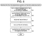
- step S41 in which the minimum radius R MIN of curvature of the curved segment defined by the curve defining equation in question is calculated, in the same manner as described above with respect to step S31.
- step S41 is followed by step S42 in which the upper limit V ARmax of the actual resultant cutter movement velocity V AR of the cutter 16 is calculated, as in step S32.
- step S43 the control flow goes to step S43 in which the CAM computer 20 receives the time interval T, and then to step S44 to calculate the length or distance L between discrete cutter path definition points to be obtained for the present curved segment.
- the time interval T is a smallest time interval at which the CNC 12 can apply successive motion commands to the NC machine tool 14 to feed the cutter 16 along each of the X-, Y- and Z-axes.
- step S45 is implemented to generate the discrete cutter path definition points on the present curved segment, as in step S36. Steps S41-S45 are repeatedly implemented for each of the curved segments of the nominal curved cutter path.
- a routine illustrated in the flow chart of Fig. 7 is executed according to the discrete point generating program corresponding to the third discrete point generating condition.
- step S51 in which the minimum radius R MIN of curvature of the curved segment in question is calculated, as in steps S31 and S41.
- step S51 is followed by step S52 in which the upper limit V ARmax of the actual resultant cutter movement velocity V AR of the cutter 16 is calculated, as in steps S32 and S42.
- step S53 the control flow goes to step S53 in which the CAM computer 20 receives the commanded rotating speed S C of the cutter 16, and the number N of the cutting blades or or inserts of the rotary cutter 16.
- step S53 is followed by step S54 to calculate the length or distance L between discrete cutter path definition points to be obtained for the present curved segment.
- step S55 is implemented to generate the discrete cutter path definition points on the present curved segment, as in steps S36 and S45. Steps S51-S55 are repeatedly implemented for each of the curved segments of the nominal curved cutter path.
- step S4 of Fig. 3 auxiliary movement data are generated to control auxiliary movements of the cutter 16 that are necessary to permit the cutting operation to be performed according to the cutter path data representative of the discrete cutter definition points.
- the auxiliary movement data include, for example, data for a non-cutting movement (rapid traverse movement) of the cutter 16 from a predetermined position (e.g., home position or tool change position) to the machining start position, data for a non-cutting movement (rapid traverse movement) of the cutter 16 from the machining end position to the predetermined position, and data for an in-feed movement of the cutter 16 from the position of one cutting pass (along a cutter path) to another cutting pass (along another cutter path), as indicated by arrow-headed lines in Fig. 10.
- step S5 the control flow goes to step S5 in which the cutter path data are converted into NC data that can be processed by the CNC 12.
- the curve defining equations representative of the curved segments of the nominal cutter paths are generated according to the equation generating programs, and a succession of discrete cutter path definition points is generated according to the selected one of the discrete point generating programs, which are independent of the equation generating programs.
- the softwares for generating the discrete cutter path definition points are independent of the softwares for generating the curve defining equations.
- interfaces are provided between the softwares for generating the curve defining equations (equation generating softwares) and the softwares for generating the discrete cutter path definition points (discrete point generating softwares), as shown in Fig. 13, by way of example.
- the equation generating software A can be replaced by the equation generating software B, independently of the discrete point generating softwares. Further, the equation generating software B can be replaced by the equation generating software D, independently of the discrete point generating softwares.
- the present arrangement has comparatively high degrees of transparency and expansibility, being capable of efficiently, economically and easily meeting changing requirements in NC machining of workpieces to manufacture currently desired parts.
- the cutter path data which represent the discrete cutter path defining points and which are generated in the CAM data processing step are converted into the NC data, which are supplied to the CNC 12.
- the CNC 12 On the basis of the NC data, the CNC 12 generates cutter motion commands to move the cutter 16 so that the cutter passes the discrete cutter path definition points.
- the curve defining equations representative of nominal cutter paths are generated in the CAM data processing step, these equations are not supplied to the CNC 12, but the cutter path data generated according to the curve defining equations are supplied to the CNC 12.
- the present embodiment may be modified such that the equation data representative of the curve defining equations as well as the cutter path data are supplied to the CNC 12 used in the NC machining step.
- the volume of the data representative of the discrete points required to accurately defining a given segment of a cutter path is considerably larger than the volume of the data representative of a curve defining equation representative of that curved segment, as is apparent from Fig. 14 which shows, in its upper part, a curved segment of a cutter path defined by discrete points, and shows in its upper part, a curved segment defined by a Bezier curve, by way of example.
- the Bezier curve is defined by a start point, an end point and two control points.
- the above modified arrangement is also effective to improve the NC machining accuracy, since the discrete points which are added by the CNC 12 for interpolation between the original discrete points also lie on the nominal cutter path (nominal curved segments defined by the curve defining equations). Where only the cutter path data representative of the discrete cutter path definition points are supplied to the CNC 12, the discrete points added by the CNC 12 do not lie on the nominal cutter path, but lie on the cutter path defined by the original discrete points generated by the CAM computer 20.
- the above modified arrangement is effective to increase the NC machining efficiency, since the cutter path defined by not only the original discrete points generated by the CAM computer 20 but also the additional discrete points generated by the CNC 12 permits a smooth movement of the cutter 16 without frequent changes in the direction of the movement and without frequent acceleration and deceleration upon such changes of the movement direction.
- the curve defining equations are generated directly on the basis of the part geometry data, and the discrete cutter path definition points are generated on the basis of the curve defining equations.
- provisional discrete cutter path definition points are generated on the basis of the part geometry data, and these provisional discrete points are used to generate the curve defining equations, which are used to generate final cutter path definition points.
- the CAM computer 20 is adapted to execute a routine illustrated in the flow chart of Fig. 16, to generate curve defining equations in the form of envelope equations, which will be described.
- a program for executing this routine is stored in the data storage medium 28 of the external memory device 26.
- step S71 the CAM computer 20 receives various kinds of data such as part geometry data described above, cutter in-feed data representative of the in-feed increment described above, and cutter radius data representative of the radius of the cutter 16.
- Step S71 is followed by step S72 to perform calculation to obtain cross sectional profiles of the part on the basis of the data received in step S71. That is, the outer profiles or outlines of the part in equally spaced-apart cross sectional planes are obtained.
- the cross sectional planes are spaced from each other by a distance equal to the in-feed increment.
- step S73 the control flow goes to step S73 to generate provisional discrete cutter path definition points on the basis of the cross sectional profiles of the part and the radius of the cutter 16.
- These provisional discrete cutter path definition points are offset from the appropriate cross sectional profiles by a distance determined by the cutter radius, in the direction away from the workpiece 18, and are substantially equally spaced apart from each other by a predetermined small distance.
- Step S74 is then implemented to generate an envelope equation representative of an envelope (.g., Bezier curve) which passes the provisional discrete cutter path definition points obtained in step S73. This envelope equation is obtained for each of segments of each nominal cutter path.
- an envelope equation representative of an envelope .g., Bezier curve
Applications Claiming Priority (3)
| Application Number | Priority Date | Filing Date | Title |
|---|---|---|---|
| JP75659/96 | 1996-03-29 | ||
| JP8075659A JP2929996B2 (ja) | 1996-03-29 | 1996-03-29 | 工具点列発生方法 |
| JP7565996 | 1996-03-29 |
Publications (3)
| Publication Number | Publication Date |
|---|---|
| EP0798616A2 true EP0798616A2 (de) | 1997-10-01 |
| EP0798616A3 EP0798616A3 (de) | 1999-04-21 |
| EP0798616B1 EP0798616B1 (de) | 2002-05-29 |
Family
ID=13582588
Family Applications (1)
| Application Number | Title | Priority Date | Filing Date |
|---|---|---|---|
| EP97105264A Expired - Lifetime EP0798616B1 (de) | 1996-03-29 | 1997-03-27 | Verfahren zur Erzeugung diskreter Punkte, die einen Schneideweg definieren, der für einen Rohling gewählte Fertigungsbedingungen erfüllt |
Country Status (5)
| Country | Link |
|---|---|
| US (1) | US5953233A (de) |
| EP (1) | EP0798616B1 (de) |
| JP (1) | JP2929996B2 (de) |
| KR (1) | KR100214230B1 (de) |
| DE (1) | DE69712824T2 (de) |
Cited By (9)
| Publication number | Priority date | Publication date | Assignee | Title |
|---|---|---|---|---|
| WO1999032949A1 (de) * | 1997-12-22 | 1999-07-01 | Eidgenössische Technische Hochschule Zürich | Verfahren zum abtragenden bearbeiten von werkstücken |
| US6491482B1 (en) * | 1999-03-08 | 2002-12-10 | Alstom (Switzerland) Ltd | Milling method |
| EP2237122A2 (de) | 2009-04-02 | 2010-10-06 | DMG Electronics GmbH | Verfahren und Vorrichtung zum Erzeugen von Steuerdaten zum Steuern eines Werkzeugs an einer Werkzeugmaschine |
| WO2010112217A1 (de) * | 2009-04-02 | 2010-10-07 | Dmg Electronics Gmbh | Verfahren und vorrichtung zum erzeugen von steuerdaten zum steuern eines werkzeugs an einer werkzeugmaschine |
| JP2010244551A (ja) * | 2009-04-06 | 2010-10-28 | Dmg Electronics Gmbh | 工作機械におけるツール制御用の制御データの生成方法および生成装置 |
| CN102640067A (zh) * | 2009-10-30 | 2012-08-15 | 株式会社牧野铣床制作所 | 刀具路径的形成方法和装置 |
| EP2634658A4 (de) * | 2010-10-25 | 2016-12-07 | Makino Milling Machine | Verfahren zur erzeugung einer werkzeugbahn und vorrichtung zur erzeugung einer werkzeugbahn |
| EP3309635A1 (de) * | 2016-10-17 | 2018-04-18 | Siemens Aktiengesellschaft | Ermittlung eines für eine jeweilige bearbeitungsmaschine optimierten teileprogramms |
| CN116859829A (zh) * | 2023-09-04 | 2023-10-10 | 天津天石休闲用品有限公司 | 基于材料边缘曲线投影的切刀运动控制方法及设备 |
Families Citing this family (16)
| Publication number | Priority date | Publication date | Assignee | Title |
|---|---|---|---|---|
| US6428252B1 (en) * | 1997-04-02 | 2002-08-06 | Tino Oldani | Method for machining |
| JPH11143511A (ja) * | 1997-11-04 | 1999-05-28 | Fanuc Ltd | 数値制御装置 |
| CN1261838C (zh) | 2000-07-31 | 2006-06-28 | 株式会社丰田中央研究所 | 综合计算机辅助制造系统,数控数据一贯生成方法,加工设计系统,加工数据生成装置及程序 |
| DE102005050205A1 (de) * | 2005-10-20 | 2007-04-26 | Mtu Aero Engines Gmbh | Verfahren und Vorrichtung zum Kompensieren von Lage-und Formabweichungen |
| DE102005050209A1 (de) * | 2005-10-20 | 2007-04-26 | Ott, Reinhold, Waterloo | Vorrichtung zur Einspeisung eines Videosignals in eine Anzeigevorrichtung und Betriebsverfahren hierfür |
| JP4796936B2 (ja) * | 2006-11-01 | 2011-10-19 | 株式会社ソディック | 加工制御装置 |
| JP4982170B2 (ja) * | 2006-12-22 | 2012-07-25 | 株式会社ソディック | 加工制御装置および加工制御プログラム |
| JP4847428B2 (ja) * | 2007-10-18 | 2011-12-28 | 株式会社ソディック | 加工シミュレーション装置およびそのプログラム |
| JP5622639B2 (ja) * | 2011-03-30 | 2014-11-12 | 三菱電機株式会社 | 指令生成装置 |
| US9507337B2 (en) * | 2011-10-27 | 2016-11-29 | Mitsubishi Electric Corporation | Numerical control device |
| EP2884361B1 (de) * | 2013-12-12 | 2022-08-10 | Siemens Aktiengesellschaft | Verfahren zum Betrieb eines Bewegungssteuerungssystems und nach dem Verfahren arbeitendes Bewegungssteuerungssystem sowie Computerprogramm zur Implementierung des Verfahrens |
| CN105373072A (zh) * | 2014-09-01 | 2016-03-02 | 富泰华工业(深圳)有限公司 | 高精度平面加工系统及方法 |
| JP6423827B2 (ja) * | 2016-07-28 | 2018-11-14 | ファナック株式会社 | 数値制御装置および工具の移動制御方法 |
| JP6386511B2 (ja) | 2016-10-28 | 2018-09-05 | ファナック株式会社 | 工具経路生成装置、工具経路生成方法及び工具経路生成プログラム |
| JP6740199B2 (ja) | 2017-10-30 | 2020-08-12 | ファナック株式会社 | 数値制御装置、cnc工作機械、数値制御方法及び数値制御用プログラム |
| JP6646027B2 (ja) | 2017-10-30 | 2020-02-14 | ファナック株式会社 | ポストプロセッサ装置、加工プログラム生成方法、cnc加工システム及び加工プログラム生成用プログラム |
Citations (2)
| Publication number | Priority date | Publication date | Assignee | Title |
|---|---|---|---|---|
| US5394323A (en) * | 1994-03-29 | 1995-02-28 | The University Of British Columbia | Path error control system |
| EP0640900A1 (de) * | 1992-10-12 | 1995-03-01 | Fanuc Ltd. | Gerat und verfahren zur numerische steuerung |
Family Cites Families (7)
| Publication number | Priority date | Publication date | Assignee | Title |
|---|---|---|---|---|
| US4453221A (en) * | 1982-05-13 | 1984-06-05 | Cincinnati Milacron Inc. | Manipulator with adaptive velocity controlled path motion |
| JPS6020209A (ja) * | 1983-07-14 | 1985-02-01 | Matsushita Electric Ind Co Ltd | ロボツトの補間制御方法 |
| US5396160A (en) * | 1991-03-11 | 1995-03-07 | General Motors Corporation | Method of real-time machine path planning from a math model |
| JPH0561516A (ja) * | 1991-09-03 | 1993-03-12 | Nikon Corp | 数値制御装置 |
| JPH05253792A (ja) * | 1992-03-16 | 1993-10-05 | Nec Corp | Ncデータ作成に於けるテーブル処理方式 |
| JPH06187029A (ja) * | 1992-12-16 | 1994-07-08 | Mitsubishi Heavy Ind Ltd | Nc制御装置 |
| JP3344811B2 (ja) * | 1994-03-03 | 2002-11-18 | 株式会社牧野フライス製作所 | 工具経路データ生成方法 |
-
1996
- 1996-03-29 JP JP8075659A patent/JP2929996B2/ja not_active Expired - Fee Related
-
1997
- 1997-03-24 US US08/822,835 patent/US5953233A/en not_active Expired - Fee Related
- 1997-03-24 KR KR1019970010068A patent/KR100214230B1/ko not_active IP Right Cessation
- 1997-03-27 EP EP97105264A patent/EP0798616B1/de not_active Expired - Lifetime
- 1997-03-27 DE DE69712824T patent/DE69712824T2/de not_active Expired - Fee Related
Patent Citations (2)
| Publication number | Priority date | Publication date | Assignee | Title |
|---|---|---|---|---|
| EP0640900A1 (de) * | 1992-10-12 | 1995-03-01 | Fanuc Ltd. | Gerat und verfahren zur numerische steuerung |
| US5394323A (en) * | 1994-03-29 | 1995-02-28 | The University Of British Columbia | Path error control system |
Non-Patent Citations (1)
| Title |
|---|
| E. SCHR]FER: "Signalverarbeitung" 1990 , HANSER , M]NCHEN XP002093762 * page 77 - page 83 * * |
Cited By (19)
| Publication number | Priority date | Publication date | Assignee | Title |
|---|---|---|---|---|
| US6485236B1 (en) | 1997-12-22 | 2002-11-26 | Starrag | Method for processing work pieces by removing material |
| CN1110730C (zh) * | 1997-12-22 | 2003-06-04 | 斯塔拉格公司 | 工件切削加工方法 |
| CZ297714B6 (cs) * | 1997-12-22 | 2007-03-14 | Starrag | Zpusob trískového obrábení povrchu obrobku |
| WO1999032949A1 (de) * | 1997-12-22 | 1999-07-01 | Eidgenössische Technische Hochschule Zürich | Verfahren zum abtragenden bearbeiten von werkstücken |
| US6491482B1 (en) * | 1999-03-08 | 2002-12-10 | Alstom (Switzerland) Ltd | Milling method |
| EP2237122A3 (de) * | 2009-04-02 | 2011-05-11 | DMG Electronics GmbH | Verfahren und Vorrichtung zum Erzeugen von Steuerdaten zum Steuern eines Werkzeugs an einer Werkzeugmaschine |
| EP2237122A2 (de) | 2009-04-02 | 2010-10-06 | DMG Electronics GmbH | Verfahren und Vorrichtung zum Erzeugen von Steuerdaten zum Steuern eines Werkzeugs an einer Werkzeugmaschine |
| WO2010112217A1 (de) * | 2009-04-02 | 2010-10-07 | Dmg Electronics Gmbh | Verfahren und vorrichtung zum erzeugen von steuerdaten zum steuern eines werkzeugs an einer werkzeugmaschine |
| US8538574B2 (en) | 2009-04-02 | 2013-09-17 | Dmg Electronics Gmbh | Method and apparatus for generating control data for controlling a tool on a machine tool |
| CN101893873A (zh) * | 2009-04-06 | 2010-11-24 | Dmg电子有限公司 | 产生用于控制机床上的刀具的控制数据的方法和装置 |
| JP2010244551A (ja) * | 2009-04-06 | 2010-10-28 | Dmg Electronics Gmbh | 工作機械におけるツール制御用の制御データの生成方法および生成装置 |
| CN101893873B (zh) * | 2009-04-06 | 2014-10-22 | Dmg电子有限公司 | 产生用于控制机床上的刀具的控制数据的方法和装置 |
| CN102640067A (zh) * | 2009-10-30 | 2012-08-15 | 株式会社牧野铣床制作所 | 刀具路径的形成方法和装置 |
| EP2495628A1 (de) * | 2009-10-30 | 2012-09-05 | Makino Milling Machine Co. Ltd. | Verfahren und vorrichtung zur tool-pfaderzeugung |
| EP2495628A4 (de) * | 2009-10-30 | 2013-07-10 | Makino Milling Machine | Verfahren und vorrichtung zur tool-pfaderzeugung |
| EP2634658A4 (de) * | 2010-10-25 | 2016-12-07 | Makino Milling Machine | Verfahren zur erzeugung einer werkzeugbahn und vorrichtung zur erzeugung einer werkzeugbahn |
| EP3309635A1 (de) * | 2016-10-17 | 2018-04-18 | Siemens Aktiengesellschaft | Ermittlung eines für eine jeweilige bearbeitungsmaschine optimierten teileprogramms |
| CN116859829A (zh) * | 2023-09-04 | 2023-10-10 | 天津天石休闲用品有限公司 | 基于材料边缘曲线投影的切刀运动控制方法及设备 |
| CN116859829B (zh) * | 2023-09-04 | 2023-11-03 | 天津天石休闲用品有限公司 | 基于材料边缘曲线投影的切刀运动控制方法及设备 |
Also Published As
| Publication number | Publication date |
|---|---|
| KR100214230B1 (ko) | 1999-08-02 |
| EP0798616B1 (de) | 2002-05-29 |
| KR970064822A (ko) | 1997-10-13 |
| DE69712824D1 (de) | 2002-07-04 |
| US5953233A (en) | 1999-09-14 |
| EP0798616A3 (de) | 1999-04-21 |
| JP2929996B2 (ja) | 1999-08-03 |
| DE69712824T2 (de) | 2002-11-14 |
| JPH09265310A (ja) | 1997-10-07 |
Similar Documents
| Publication | Publication Date | Title |
|---|---|---|
| US5953233A (en) | Process of generating discrete points defining cutter path, so as to meet selected workpiece machining requirements | |
| KR100253684B1 (ko) | 가공능률을향상시키기위해가공기의능력을고려하여커터경로를규정하는이산점들을생성하는방법 | |
| EP0258897B1 (de) | Verfahren und Anlage für die automatische Erzeugung von Werkzeugbahndaten für eine automatische Bearbeitungszentrale | |
| US5396160A (en) | Method of real-time machine path planning from a math model | |
| US4833617A (en) | Solid modeling based adaptive feedrate control for NC machining | |
| Lin | Real-time surface interpolator for 3-D parametric surface machining on 3-axis machine tools | |
| JP4233147B2 (ja) | 工作機械用に適応可能なフィードレートを決定する方法 | |
| US7444202B2 (en) | Method for smoothing polylines in NC programs | |
| JP3587363B2 (ja) | 数値制御装置及び数値制御方法 | |
| Petrakov et al. | Technology for programming contour milling on a CNC machine | |
| Lin et al. | Real-time interpolators for multi-axis CNC machine tools | |
| JP2676506B2 (ja) | レーザ加工用運動制御方法 | |
| Estrems et al. | Trajectory generation in 5-axis milling of freeform surfaces using circular arc approximation and its influence in surface roughness | |
| JPH06119031A (ja) | 削り残し部加工のncデータ作成方法 | |
| Lin et al. | Ruled surface machining on five-axis CNC machine tools | |
| JPH0446705B2 (de) | ||
| JPH07261815A (ja) | Nc加工用工具加工経路作成方法およびその装置 | |
| JPH0767659B2 (ja) | 仕上げ表面あらさを考慮した自由曲面の加工情報生成システム | |
| JPH0635096B2 (ja) | Nc加工方法と装置 | |
| Morikawa et al. | 5-Axis control tool path generation using curved surface interpolation | |
| Kruth et al. | A generalized post-processor and process-planner for five-axes wire EDM-machines | |
| JP2531149B2 (ja) | 仕上げ精度を考慮した自由曲面の加工情報生成方法 | |
| JPH10307615A (ja) | Cam用凹溝部位の加工経路自動生成方法 | |
| Srinathu | Real-Time Manufacturing Control Strategies Based on Open-Architecture Systems and Precise CAD Geometry | |
| CN112100823A (zh) | 刀具纳米级精度设计制造方法 |
Legal Events
| Date | Code | Title | Description |
|---|---|---|---|
| PUAI | Public reference made under article 153(3) epc to a published international application that has entered the european phase |
Free format text: ORIGINAL CODE: 0009012 |
|
| 17P | Request for examination filed |
Effective date: 19970327 |
|
| AK | Designated contracting states |
Kind code of ref document: A2 Designated state(s): DE FR GB |
|
| PUAL | Search report despatched |
Free format text: ORIGINAL CODE: 0009013 |
|
| AK | Designated contracting states |
Kind code of ref document: A3 Designated state(s): DE FR GB |
|
| 17Q | First examination report despatched |
Effective date: 19990614 |
|
| GRAG | Despatch of communication of intention to grant |
Free format text: ORIGINAL CODE: EPIDOS AGRA |
|
| GRAG | Despatch of communication of intention to grant |
Free format text: ORIGINAL CODE: EPIDOS AGRA |
|
| GRAH | Despatch of communication of intention to grant a patent |
Free format text: ORIGINAL CODE: EPIDOS IGRA |
|
| GRAH | Despatch of communication of intention to grant a patent |
Free format text: ORIGINAL CODE: EPIDOS IGRA |
|
| GRAA | (expected) grant |
Free format text: ORIGINAL CODE: 0009210 |
|
| AK | Designated contracting states |
Kind code of ref document: B1 Designated state(s): DE FR GB |
|
| REG | Reference to a national code |
Ref country code: GB Ref legal event code: FG4D |
|
| REF | Corresponds to: |
Ref document number: 69712824 Country of ref document: DE Date of ref document: 20020704 |
|
| ET | Fr: translation filed | ||
| PLBE | No opposition filed within time limit |
Free format text: ORIGINAL CODE: 0009261 |
|
| STAA | Information on the status of an ep patent application or granted ep patent |
Free format text: STATUS: NO OPPOSITION FILED WITHIN TIME LIMIT |
|
| 26N | No opposition filed |
Effective date: 20030303 |
|
| PGFP | Annual fee paid to national office [announced via postgrant information from national office to epo] |
Ref country code: GB Payment date: 20090325 Year of fee payment: 13 |
|
| PGFP | Annual fee paid to national office [announced via postgrant information from national office to epo] |
Ref country code: DE Payment date: 20090319 Year of fee payment: 13 |
|
| PGFP | Annual fee paid to national office [announced via postgrant information from national office to epo] |
Ref country code: FR Payment date: 20090316 Year of fee payment: 13 |
|
| GBPC | Gb: european patent ceased through non-payment of renewal fee |
Effective date: 20100327 |
|
| REG | Reference to a national code |
Ref country code: FR Ref legal event code: ST Effective date: 20101130 |
|
| PG25 | Lapsed in a contracting state [announced via postgrant information from national office to epo] |
Ref country code: FR Free format text: LAPSE BECAUSE OF NON-PAYMENT OF DUE FEES Effective date: 20100331 |
|
| PG25 | Lapsed in a contracting state [announced via postgrant information from national office to epo] |
Ref country code: DE Free format text: LAPSE BECAUSE OF NON-PAYMENT OF DUE FEES Effective date: 20101001 |
|
| PG25 | Lapsed in a contracting state [announced via postgrant information from national office to epo] |
Ref country code: GB Free format text: LAPSE BECAUSE OF NON-PAYMENT OF DUE FEES Effective date: 20100327 |