EP0798484B1 - Rotationsdämpfer - Google Patents
Rotationsdämpfer Download PDFInfo
- Publication number
- EP0798484B1 EP0798484B1 EP97103664A EP97103664A EP0798484B1 EP 0798484 B1 EP0798484 B1 EP 0798484B1 EP 97103664 A EP97103664 A EP 97103664A EP 97103664 A EP97103664 A EP 97103664A EP 0798484 B1 EP0798484 B1 EP 0798484B1
- Authority
- EP
- European Patent Office
- Prior art keywords
- rotary damper
- damper according
- bearing part
- damping element
- shaft
- Prior art date
- Legal status (The legal status is an assumption and is not a legal conclusion. Google has not performed a legal analysis and makes no representation as to the accuracy of the status listed.)
- Expired - Lifetime
Links
Images

Classifications
-
- F—MECHANICAL ENGINEERING; LIGHTING; HEATING; WEAPONS; BLASTING
- F16—ENGINEERING ELEMENTS AND UNITS; GENERAL MEASURES FOR PRODUCING AND MAINTAINING EFFECTIVE FUNCTIONING OF MACHINES OR INSTALLATIONS; THERMAL INSULATION IN GENERAL
- F16F—SPRINGS; SHOCK-ABSORBERS; MEANS FOR DAMPING VIBRATION
- F16F7/00—Vibration-dampers; Shock-absorbers
- F16F7/02—Vibration-dampers; Shock-absorbers with relatively-rotatable friction surfaces that are pressed together
- F16F7/06—Vibration-dampers; Shock-absorbers with relatively-rotatable friction surfaces that are pressed together in a direction perpendicular or inclined to the axis of rotation
-
- F—MECHANICAL ENGINEERING; LIGHTING; HEATING; WEAPONS; BLASTING
- F16—ENGINEERING ELEMENTS AND UNITS; GENERAL MEASURES FOR PRODUCING AND MAINTAINING EFFECTIVE FUNCTIONING OF MACHINES OR INSTALLATIONS; THERMAL INSULATION IN GENERAL
- F16F—SPRINGS; SHOCK-ABSORBERS; MEANS FOR DAMPING VIBRATION
- F16F15/00—Suppression of vibrations in systems; Means or arrangements for avoiding or reducing out-of-balance forces, e.g. due to motion
- F16F15/10—Suppression of vibrations in rotating systems by making use of members moving with the system
-
- Y—GENERAL TAGGING OF NEW TECHNOLOGICAL DEVELOPMENTS; GENERAL TAGGING OF CROSS-SECTIONAL TECHNOLOGIES SPANNING OVER SEVERAL SECTIONS OF THE IPC; TECHNICAL SUBJECTS COVERED BY FORMER USPC CROSS-REFERENCE ART COLLECTIONS [XRACs] AND DIGESTS
- Y10—TECHNICAL SUBJECTS COVERED BY FORMER USPC
- Y10T—TECHNICAL SUBJECTS COVERED BY FORMER US CLASSIFICATION
- Y10T74/00—Machine element or mechanism
- Y10T74/20—Control lever and linkage systems
- Y10T74/20576—Elements
- Y10T74/20636—Detents
- Y10T74/2066—Friction
Definitions
- the invention relates to a rotary damper, with a permanently arranged in a housing, made of plastic Bearing part and one arranged therein, with a connected at least partially rotatable shaft about its longitudinal axis, rotor part also made of plastic, wherein a damping device is located between the bearing part and the rotor part located.
- a rotary damper is already known as prior art, in which the housing on its outer circumference with a Gear part is provided, the shaft of the rotor via a Cap protrudes (DE 43 15 294 A1).
- the cap is here locked and located behind a projection of the housing between a sealing washer and one facing the shaft End face of the rotor. That turned away from the wave End face of the rotor is provided with a space, in which there is a viscous medium.
- the gap can either be in the form of a closed disc or a ring. As a result of the small gap the damping effect is thus to absorb the viscous medium relatively low.
- the prior art also includes a rotary damper, in which a coil spring between an inner boundary surface the cylindrical wall of the housing and one outer boundary surface of the cylindrical rotor is (DE 38 21 982 A1).
- a coil spring between an inner boundary surface the cylindrical wall of the housing and one outer boundary surface of the cylindrical rotor is (DE 38 21 982 A1).
- the object of the present invention in creating a rotary damper which, while avoiding the use of viscous medium with simpler Structure has good damping ability.
- the rotor part one in a circumferential recess of the damping element projecting web, which with at least one axially extending rib is provided.
- the recess in which the web is inserted can be funnel-shaped in cross section with the front narrower opening area.
- a collar can be used to connect the bearing part to the rotor part of the rotor part have a circumferential groove on its outer circumference, into which a molded on the inner circumference of the bearing part, circumferential engagement ring can be stored.
- Locking zones can be used to connect the rotor part to the bearing part Find application, for example, about the scope the end face of the rotor part are arranged and in can store corresponding recesses of the bearing part.
- the bearing part on its outer circumference have at least one locking element which for Rotation lock serves.
- a rotary damper 1 is shown, which essentially made of a plastic Bearing part 2, a rotor part 3 arranged therein and a Damping element arranged between rotor part 3 and bearing part 2 4 exists.
- the bearing part 2 can be via a locking element 30, which is arranged on the outer circumference, against rotation arrange in a larger unit.
- the rotor part 3 is mounted on a rotatable shaft 8.
- the rotor part 3 a web 20 which in the illustrated in the figures Embodiment on its inner circumference and on its outer circumference distributed has several ribs 6, 6 '.
- the web 20 of the rotor part 3 protrudes into a recess 10 of the Damping element 4. From Fig. 2 it can be seen that this recess 10 of the damping element 4 funnel-shaped in cross section is designed with a narrower opening area on the end face 11.
- the web 20 of the rotor part 3 can be rectangular in cross section be designed.
- the ribs 6, 6 ' serve as an engagement part 5, 5', which at Rotating the shaft 8 a rotational resistance in the damping element 4 generate, namely that the web 20 with the Ribs 6, 6 ′ in the recess 10 of the damping element 4 intervenes.
- the bearing part and the damping element 4 can be in the two-component injection molding process be made. It also exists the possibility that the damping element 4 at its the Bearing part 2 facing end face 15 one in the adjacent Surface of the bearing part 2 has interlocking locking zone 16.
- the surface of the bearing part 2 with recesses 18 provided, in which, for example, 3 over the Circumference of the end face 15 distributed locking zones according to Fig. 3b or 4a and Fig. 2 can store. This is a positive Holding the damping element 4 within the Bearing part 2 guaranteed.
- the rotor part 3 has a connectable to the shaft 8, circumferential collar 21, on which on an end face 22 of the Web is formed.
- the collar 21 is 23 over its outer circumference connectable to the bearing part 2.
- the federal government has 21 2 a circumferential groove 24 on its outer circumference 23, in which a molded on the inner circumference of the bearing part 2, circumferential engagement ring 25 (Fig. 4a) can be stored.
- Rotation damper can be used for example at a flap of a glove compartment of a motor vehicle, at a closure for an ashtray, with a swiveling one Handle or with control flaps of hi-fi devices or dictation machines.
Landscapes
- Engineering & Computer Science (AREA)
- General Engineering & Computer Science (AREA)
- Mechanical Engineering (AREA)
- Physics & Mathematics (AREA)
- Acoustics & Sound (AREA)
- Aviation & Aerospace Engineering (AREA)
- Fluid-Damping Devices (AREA)
- Vibration Dampers (AREA)
- Vibration Prevention Devices (AREA)
- Support Of The Bearing (AREA)
Description
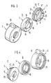
- Fig. 1
- eine Vorderansicht des Rotationsdämpfers
- Fig. 2
- einen Schnitt nach der Linie II-II in Fig. 1
- Fig. 3 u. Fig. 4a, b, c
- jeweils perspektivische Ansichten des Lagerteils, des Rotorteils und des Dämpfungselements in Vorder- bzw. in Rückansicht.
Claims (15)
- Rotationsdämpfer, mit einem in einem Gehäuse fest angeordneten, aus Kunststoff bestehenden Lagerteil und einem darin angeordneten, mit einer zumindest teilweise um ihre Längsachse drehbaren Welle verbundenen, ebenfalls aus Kunststoff bestehenden Rotorteil, wobei sich zwischen dem Lagerteil und dem Rotorteil eine Dämpfungseinrichtung befindet,
dadurch gekennzeichnet,daß in dem Lagerteil (2) drehfest ein die Welle (8) umgebendes, aus dämpfendem Kunststoff bestehendes Dämpfungselement (4) angeordnet ist unddaß das Rotorteil (3) und/oder das Dämpfungselement (4) jeweils mindestens ein bei Drehen der Welle (8) einen Rotationswiderstand erzeugendes Eingriffsteil (5, 5') aufweist. - Rotationsdämpfer nach Anspruch 1, dadurch gekennzeichnet, daß das Eingriffsteil (5, 5') als eine axial zur Welle (8) verlaufende Rippe (6, 6') ausgebildet ist.
- Rotationsdämpfer nach Anspruch 1 und 2, dadurch gekennzeichnet, daß das Rotorteil (3) einen in eine umlaufende Ausnehmung (10) des Dämpfungselements (4) ragenden Steg (20) aufweist, welcher mit mindestens einer axial verlaufenden Rippe (6, 6') versehen ist.
- Rotationsdämpfer nach Anspruch 3, dadurch gekennzeichnet, daß der Steg (20) über den Innen- und/oder Außenumfang verteilt mehrere Rippen (6, 6') aufweist.
- Rotationsdämpfer nach Anspruch 4, gekennzeichnet durch drei über den Innen- und/oder Außenumfang verteilte Rippen (6, 6').
- Rotationsdämpfer nach Anspruch 3 bis 5, dadurch gekennzeichnet, daß die Ausnehmung (10) des Dämpfungselements (4) im Querschnitt trichterförmig ausgebildet ist mit stirnseitig engerem Öffnungsbereich (11).
- Rotationsdämpfer nach Anspruch 3 bis 6, dadurch gekennzeichnet, daß der Steg (20) im Querschnitt rechteckig ausgebildet ist.
- Rotationsdämpfer nach einem der vorhergehenden Ansprüche, dadurch gekennzeichnet, daß das Rotorteil (3) einen mit der Welle (8) verbindbaren umlaufenden Bund (21) aufweist, an welchen an einer Stirnseite (22) der Steg (20) angeformt ist.
- Rotationsdämpfer nach Anspruch 8, dadurch gekennzeichnet, daß der Bund (21) über seinen Außenumfang (23) mit dem Lagerteil (2) verbunden ist.
- Rotationsdämpfer nach Anspruch 9, dadurch gekennzeichnet, daß der Bund (21) eine umlaufende Nut (24) an seinem Außenumfang (23) aufweist, in welcher ein am Innenumfang des Lagerteils (2) angeformter, umlaufender Eingriffsring (25) einlagerbar ist.
- Rotationsdämpfer nach einem der vorhergehenden Ansprüche, dadurch gekennzeichnet, daß das Dämpfungselement (4) an seiner dem Lagerteil (2) zugekehrten Stirnseite (15) mindestens eine, sich in die angrenzende Fläche des Lagerteils (2) einlagernde Rastzone (16) aufweist.
- Rotationsdämpfer nach Anspruch 11, gekennzeichnet durch drei über den Umfang der Stirnseite (15) verteilte Rastzonen (16), welche in entsprechende Aussparungen (18) des Lagerteils (2) einlagerbar sind.
- Rotationsdämpfer nach einem der vorhergehenden Ansprüche, dadurch gekennzeichnet, daß das Lagerteil (2) und das Dämpfungselement (4) im Zweikomponenten-Spritzverfahren hergestellt sind.
- Rotationsdämpfer nach einem der vorhergehenden Ansprüche, dadurch gekennzeichnet, daß das Lagerteil (2) das Dämpfungselement (4) und das Rotorteil (3) überdeckt.
- Rotationsdämpfer nach einem der vorhergehenden Ansprüche, dadurch gekennzeichnet, daß das Lagerteil (2) an seinem Außenumfang mindestens ein Arretierelement (30) aufweist.
Applications Claiming Priority (2)
| Application Number | Priority Date | Filing Date | Title |
|---|---|---|---|
| DE19611725 | 1996-03-25 | ||
| DE19611725A DE19611725C1 (de) | 1996-03-25 | 1996-03-25 | Rotationsdämpfer |
Publications (3)
| Publication Number | Publication Date |
|---|---|
| EP0798484A2 EP0798484A2 (de) | 1997-10-01 |
| EP0798484A3 EP0798484A3 (de) | 1998-07-08 |
| EP0798484B1 true EP0798484B1 (de) | 2001-06-27 |
Family
ID=7789340
Family Applications (1)
| Application Number | Title | Priority Date | Filing Date |
|---|---|---|---|
| EP97103664A Expired - Lifetime EP0798484B1 (de) | 1996-03-25 | 1997-03-05 | Rotationsdämpfer |
Country Status (6)
| Country | Link |
|---|---|
| US (1) | US5865278A (de) |
| EP (1) | EP0798484B1 (de) |
| JP (2) | JPH102366A (de) |
| KR (1) | KR100517473B1 (de) |
| DE (2) | DE19611725C1 (de) |
| ES (1) | ES2158392T3 (de) |
Families Citing this family (14)
| Publication number | Priority date | Publication date | Assignee | Title |
|---|---|---|---|---|
| DE19631384C1 (de) * | 1996-08-02 | 1997-10-16 | Clouth Gummiwerke Ag | Elektrische Maschine in einem Antriebsstrang, z. B. eines Kraftfahrzeuges |
| CN1065176C (zh) * | 1997-02-25 | 2001-05-02 | 花王株式会社 | 吹模机的合模装置 |
| US6129186A (en) * | 1998-04-03 | 2000-10-10 | Trw Inc. | Rotational damper |
| US6367124B1 (en) * | 1999-09-09 | 2002-04-09 | Illinois Tool Works Inc. | Damper and a door handle |
| US6840353B2 (en) * | 2000-10-26 | 2005-01-11 | Piolax, Inc. | Rotary damper |
| US7753181B2 (en) * | 2005-01-31 | 2010-07-13 | Illinois Tool Works Inc. | Damper having silicone impregnated and silicone containing components |
| US20060249343A1 (en) * | 2005-05-06 | 2006-11-09 | Suspa Holding Gmbh | Rotary damper |
| JP4848350B2 (ja) * | 2007-11-29 | 2011-12-28 | 株式会社アドバネクス | 回転ダンパー |
| DE102008048320A1 (de) | 2008-09-22 | 2010-04-01 | Ejot Gmbh & Co. Kg | Drehbewegungsdämpfer |
| CN104100464B (zh) * | 2014-07-03 | 2016-07-06 | 株洲时代新材料科技股份有限公司 | 一种风力发电机齿轮箱减振器及其减振保护方法 |
| CN106437369B (zh) * | 2016-10-28 | 2017-12-05 | 深圳市宝科特精密科技有限公司 | 阻尼旋转连接结构 |
| CN109164869B (zh) * | 2018-10-30 | 2024-04-09 | 深圳和而泰智能控制股份有限公司 | 阻尼旋转结构及其档位调节器 |
| CN109027089B (zh) * | 2018-10-31 | 2023-11-21 | 歌尔科技有限公司 | 一种减震装置、回转组件及电子设备 |
| KR102231167B1 (ko) * | 2020-12-20 | 2021-03-22 | 조남홍 | 야외에 설치되는 운동기구를 위한 베어링 구조체 |
Family Cites Families (20)
| Publication number | Priority date | Publication date | Assignee | Title |
|---|---|---|---|---|
| DE2906288C2 (de) * | 1979-02-19 | 1981-05-21 | Kunststoffwerk Philippine Gmbh & Co Kg, 5420 Lahnstein | Anbauteil zum Anschluß an eine Wandung, insbesondere Griff oder Armlehne zum Anschluß an ein Karosserieteil eines Kraftfahrzeuges |
| JPS6213242U (de) * | 1985-07-10 | 1987-01-27 | ||
| JPH0742999B2 (ja) * | 1986-08-05 | 1995-05-15 | 株式会社ニフコ | オイル式ダンパ− |
| JP2544628B2 (ja) * | 1987-07-10 | 1996-10-16 | 株式会社 ニフコ | 回転ダンパ− |
| US4833938A (en) * | 1987-08-10 | 1989-05-30 | Elco Industries, Inc. | Rotary motion dampener |
| JPH0158839U (de) * | 1987-10-08 | 1989-04-13 | ||
| US4840083A (en) * | 1988-03-14 | 1989-06-20 | Elco Industries, Inc. | Device for dampening rotary motion |
| US4981322A (en) * | 1988-06-10 | 1991-01-01 | United Technologies Corporation, Inc. | Assist strap for a motor vehicle |
| DE3829209A1 (de) * | 1988-08-29 | 1990-03-15 | Happich Gmbh Gebr | Haltegriff fuer fahrzeuge |
| JPH05149359A (ja) * | 1991-11-29 | 1993-06-15 | Nippon Plast Co Ltd | 回転ダンパー |
| JP3175019B2 (ja) * | 1991-12-17 | 2001-06-11 | 株式会社ニフコ | 回転ダンパー |
| US5257680A (en) * | 1991-12-20 | 1993-11-02 | Lord Corporation | Surface effect dampers having both hysteresis and a frictional component |
| JP3459078B2 (ja) * | 1992-05-08 | 2003-10-20 | 株式会社ニフコ | 回転ダンパー |
| DE4244484C2 (de) * | 1992-12-30 | 2003-04-17 | Itw Ateco Gmbh | Rotationsdämpfer |
| DE4309024A1 (de) * | 1993-03-20 | 1994-09-22 | Happich Gmbh Gebr | Befestigungselement für an Karosserieteilen von Kraftfahrzeugen zu befestigende Ausstattungsteile |
| DE4323095C1 (de) * | 1993-07-10 | 1994-10-20 | Raymond A Gmbh & Co Kg | Bremselement zur Dämpfung einer Schubbewegung |
| DE9320677U1 (de) * | 1993-09-03 | 1994-11-17 | Itw Ateco Gmbh | Rotationsdämpfer |
| SE509769C2 (sv) * | 1993-09-03 | 1999-03-08 | Itw Ateco Gmbh | Rotationsdämpare |
| DE9420646U1 (de) * | 1994-12-23 | 1995-02-16 | Itw Ateco Gmbh | Rotationsdämpfer |
| US5660254A (en) * | 1995-12-04 | 1997-08-26 | Illinois Tool Works Inc. | Dry rotary damper |
-
1996
- 1996-03-25 DE DE19611725A patent/DE19611725C1/de not_active Expired - Fee Related
-
1997
- 1997-03-05 DE DE59703885T patent/DE59703885D1/de not_active Expired - Fee Related
- 1997-03-05 ES ES97103664T patent/ES2158392T3/es not_active Expired - Lifetime
- 1997-03-05 EP EP97103664A patent/EP0798484B1/de not_active Expired - Lifetime
- 1997-03-25 US US08/823,988 patent/US5865278A/en not_active Expired - Fee Related
- 1997-03-25 KR KR1019970010694A patent/KR100517473B1/ko not_active IP Right Cessation
- 1997-03-25 JP JP9071072A patent/JPH102366A/ja active Pending
-
2002
- 2002-02-07 JP JP2002000509U patent/JP3087811U/ja not_active Expired - Lifetime
Also Published As
| Publication number | Publication date |
|---|---|
| JP3087811U (ja) | 2002-08-23 |
| EP0798484A2 (de) | 1997-10-01 |
| US5865278A (en) | 1999-02-02 |
| DE19611725C1 (de) | 1997-11-13 |
| KR100517473B1 (ko) | 2005-11-25 |
| KR970066156A (ko) | 1997-10-13 |
| EP0798484A3 (de) | 1998-07-08 |
| ES2158392T3 (es) | 2001-09-01 |
| JPH102366A (ja) | 1998-01-06 |
| DE59703885D1 (de) | 2001-08-02 |
Similar Documents
| Publication | Publication Date | Title |
|---|---|---|
| EP0798484B1 (de) | Rotationsdämpfer | |
| DE19636475B4 (de) | Rotationsdämpfer | |
| EP1875090B9 (de) | Verfahren zum lagern einer welle sowie lageranordnung | |
| DE102007060149A1 (de) | Teleskopierbare Lenkspindelanordnung | |
| DE19811421C2 (de) | Tankreinigungsvorrichtung | |
| DE19807953A1 (de) | Verbindung zwischen einem Träger und einem Plattenelement | |
| DE4443422A1 (de) | Wellendichtring mit einer elastischen Dichtlippe | |
| EP1259744A1 (de) | Drehfedersatz | |
| EP1428305A1 (de) | Geräuschgedämmte halterung eines elektromotors | |
| DE19851816B4 (de) | Wischervorrichtung für Fahrzeuge | |
| EP0500868B1 (de) | Antriebsvorrichtung, insbesondere für scheibenwischer an kraftfahrzeugen | |
| EP0918671A1 (de) | Elektrische antriebseinheit | |
| DE102007000941B4 (de) | Wellgetriebe | |
| DE19613325C1 (de) | Torsionsschwingungsdämpfer mit einer Schmierstoffzuführung für ein Planetenrad | |
| DE2730474C2 (de) | ||
| DE10018108C2 (de) | Getriebebeschlag für einen Fahrzeugsitzeinsteller | |
| DE19850423C2 (de) | Kugelgelenk | |
| DE19755947B4 (de) | Drehdämpfer | |
| DE4123494C2 (de) | Dichtungsvorrichtung | |
| EP0984196A1 (de) | Drehzahladaptiver Schwingungstilger | |
| DE2626834A1 (de) | Achslager | |
| EP1034959B1 (de) | Verschluss an einem Einfüllstutzen eines Behälters, insbesondere an einem Kraftfahrzeug | |
| DE4002318C1 (en) | Drive for vehicle sliding roof - has index wheel driving gear wheel with interlocking radial stop profiles | |
| DE10235550A1 (de) | Drehdämpfer | |
| DE3911106A1 (de) | Wischblatt-mitnahmevorrichtung zur bewegung in die ausgangsstellung |
Legal Events
| Date | Code | Title | Description |
|---|---|---|---|
| PUAI | Public reference made under article 153(3) epc to a published international application that has entered the european phase |
Free format text: ORIGINAL CODE: 0009012 |
|
| AK | Designated contracting states |
Kind code of ref document: A2 Designated state(s): DE ES FR GB IT |
|
| PUAL | Search report despatched |
Free format text: ORIGINAL CODE: 0009013 |
|
| AK | Designated contracting states |
Kind code of ref document: A3 Designated state(s): DE ES FR GB IT |
|
| 17P | Request for examination filed |
Effective date: 19980616 |
|
| GRAG | Despatch of communication of intention to grant |
Free format text: ORIGINAL CODE: EPIDOS AGRA |
|
| GRAG | Despatch of communication of intention to grant |
Free format text: ORIGINAL CODE: EPIDOS AGRA |
|
| GRAH | Despatch of communication of intention to grant a patent |
Free format text: ORIGINAL CODE: EPIDOS IGRA |
|
| 17Q | First examination report despatched |
Effective date: 20001117 |
|
| RAP1 | Party data changed (applicant data changed or rights of an application transferred) |
Owner name: TRW AUTOMOTIVE ELECTRONICS & COMPONENTS GMBH & CO. |
|
| GRAH | Despatch of communication of intention to grant a patent |
Free format text: ORIGINAL CODE: EPIDOS IGRA |
|
| GRAA | (expected) grant |
Free format text: ORIGINAL CODE: 0009210 |
|
| AK | Designated contracting states |
Kind code of ref document: B1 Designated state(s): DE ES FR GB IT |
|
| REF | Corresponds to: |
Ref document number: 59703885 Country of ref document: DE Date of ref document: 20010802 |
|
| REG | Reference to a national code |
Ref country code: ES Ref legal event code: FG2A Ref document number: 2158392 Country of ref document: ES Kind code of ref document: T3 |
|
| GBT | Gb: translation of ep patent filed (gb section 77(6)(a)/1977) |
Effective date: 20010824 |
|
| ITF | It: translation for a ep patent filed |
Owner name: IPSER S.R.L. |
|
| ET | Fr: translation filed | ||
| REG | Reference to a national code |
Ref country code: GB Ref legal event code: IF02 |
|
| PLBE | No opposition filed within time limit |
Free format text: ORIGINAL CODE: 0009261 |
|
| STAA | Information on the status of an ep patent application or granted ep patent |
Free format text: STATUS: NO OPPOSITION FILED WITHIN TIME LIMIT |
|
| 26N | No opposition filed | ||
| PGFP | Annual fee paid to national office [announced via postgrant information from national office to epo] |
Ref country code: GB Payment date: 20070202 Year of fee payment: 11 |
|
| PGFP | Annual fee paid to national office [announced via postgrant information from national office to epo] |
Ref country code: ES Payment date: 20070313 Year of fee payment: 11 |
|
| PGFP | Annual fee paid to national office [announced via postgrant information from national office to epo] |
Ref country code: DE Payment date: 20070330 Year of fee payment: 11 |
|
| PGFP | Annual fee paid to national office [announced via postgrant information from national office to epo] |
Ref country code: IT Payment date: 20070529 Year of fee payment: 11 |
|
| PGFP | Annual fee paid to national office [announced via postgrant information from national office to epo] |
Ref country code: FR Payment date: 20070301 Year of fee payment: 11 |
|
| GBPC | Gb: european patent ceased through non-payment of renewal fee |
Effective date: 20080305 |
|
| REG | Reference to a national code |
Ref country code: FR Ref legal event code: ST Effective date: 20081125 |
|
| PG25 | Lapsed in a contracting state [announced via postgrant information from national office to epo] |
Ref country code: DE Free format text: LAPSE BECAUSE OF NON-PAYMENT OF DUE FEES Effective date: 20081001 |
|
| PG25 | Lapsed in a contracting state [announced via postgrant information from national office to epo] |
Ref country code: FR Free format text: LAPSE BECAUSE OF NON-PAYMENT OF DUE FEES Effective date: 20080331 |
|
| REG | Reference to a national code |
Ref country code: ES Ref legal event code: FD2A Effective date: 20080306 |
|
| PG25 | Lapsed in a contracting state [announced via postgrant information from national office to epo] |
Ref country code: GB Free format text: LAPSE BECAUSE OF NON-PAYMENT OF DUE FEES Effective date: 20080305 |
|
| PG25 | Lapsed in a contracting state [announced via postgrant information from national office to epo] |
Ref country code: ES Free format text: LAPSE BECAUSE OF NON-PAYMENT OF DUE FEES Effective date: 20080306 |
|
| PG25 | Lapsed in a contracting state [announced via postgrant information from national office to epo] |
Ref country code: IT Free format text: LAPSE BECAUSE OF NON-PAYMENT OF DUE FEES Effective date: 20080305 |