EP0798143A1 - Méthode et dispositif pour purifier de l'air comprenant une réactivation d'adsorbant - Google Patents
Méthode et dispositif pour purifier de l'air comprenant une réactivation d'adsorbant Download PDFInfo
- Publication number
- EP0798143A1 EP0798143A1 EP97104777A EP97104777A EP0798143A1 EP 0798143 A1 EP0798143 A1 EP 0798143A1 EP 97104777 A EP97104777 A EP 97104777A EP 97104777 A EP97104777 A EP 97104777A EP 0798143 A1 EP0798143 A1 EP 0798143A1
- Authority
- EP
- European Patent Office
- Prior art keywords
- air
- automobile
- purifying apparatus
- adsorbing
- photocatalyst
- Prior art date
- Legal status (The legal status is an assumption and is not a legal conclusion. Google has not performed a legal analysis and makes no representation as to the accuracy of the status listed.)
- Withdrawn
Links
Images


Classifications
-
- B—PERFORMING OPERATIONS; TRANSPORTING
- B60—VEHICLES IN GENERAL
- B60H—ARRANGEMENTS OF HEATING, COOLING, VENTILATING OR OTHER AIR-TREATING DEVICES SPECIALLY ADAPTED FOR PASSENGER OR GOODS SPACES OF VEHICLES
- B60H1/00—Heating, cooling or ventilating [HVAC] devices
- B60H1/00642—Control systems or circuits; Control members or indication devices for heating, cooling or ventilating devices
- B60H1/00735—Control systems or circuits characterised by their input, i.e. by the detection, measurement or calculation of particular conditions, e.g. signal treatment, dynamic models
- B60H1/008—Control systems or circuits characterised by their input, i.e. by the detection, measurement or calculation of particular conditions, e.g. signal treatment, dynamic models the input being air quality
-
- B—PERFORMING OPERATIONS; TRANSPORTING
- B01—PHYSICAL OR CHEMICAL PROCESSES OR APPARATUS IN GENERAL
- B01D—SEPARATION
- B01D53/00—Separation of gases or vapours; Recovering vapours of volatile solvents from gases; Chemical or biological purification of waste gases, e.g. engine exhaust gases, smoke, fumes, flue gases, aerosols
- B01D53/007—Separation of gases or vapours; Recovering vapours of volatile solvents from gases; Chemical or biological purification of waste gases, e.g. engine exhaust gases, smoke, fumes, flue gases, aerosols by irradiation
-
- B—PERFORMING OPERATIONS; TRANSPORTING
- B01—PHYSICAL OR CHEMICAL PROCESSES OR APPARATUS IN GENERAL
- B01D—SEPARATION
- B01D53/00—Separation of gases or vapours; Recovering vapours of volatile solvents from gases; Chemical or biological purification of waste gases, e.g. engine exhaust gases, smoke, fumes, flue gases, aerosols
- B01D53/34—Chemical or biological purification of waste gases
- B01D53/74—General processes for purification of waste gases; Apparatus or devices specially adapted therefor
- B01D53/86—Catalytic processes
- B01D53/8621—Removing nitrogen compounds
- B01D53/8625—Nitrogen oxides
-
- B—PERFORMING OPERATIONS; TRANSPORTING
- B01—PHYSICAL OR CHEMICAL PROCESSES OR APPARATUS IN GENERAL
- B01D—SEPARATION
- B01D53/00—Separation of gases or vapours; Recovering vapours of volatile solvents from gases; Chemical or biological purification of waste gases, e.g. engine exhaust gases, smoke, fumes, flue gases, aerosols
- B01D53/34—Chemical or biological purification of waste gases
- B01D53/74—General processes for purification of waste gases; Apparatus or devices specially adapted therefor
- B01D53/86—Catalytic processes
- B01D53/8668—Removing organic compounds not provided for in B01D53/8603 - B01D53/8665
-
- B—PERFORMING OPERATIONS; TRANSPORTING
- B60—VEHICLES IN GENERAL
- B60H—ARRANGEMENTS OF HEATING, COOLING, VENTILATING OR OTHER AIR-TREATING DEVICES SPECIALLY ADAPTED FOR PASSENGER OR GOODS SPACES OF VEHICLES
- B60H3/00—Other air-treating devices
- B60H3/06—Filtering
-
- B—PERFORMING OPERATIONS; TRANSPORTING
- B01—PHYSICAL OR CHEMICAL PROCESSES OR APPARATUS IN GENERAL
- B01D—SEPARATION
- B01D2255/00—Catalysts
- B01D2255/80—Type of catalytic reaction
- B01D2255/802—Photocatalytic
-
- B—PERFORMING OPERATIONS; TRANSPORTING
- B60—VEHICLES IN GENERAL
- B60H—ARRANGEMENTS OF HEATING, COOLING, VENTILATING OR OTHER AIR-TREATING DEVICES SPECIALLY ADAPTED FOR PASSENGER OR GOODS SPACES OF VEHICLES
- B60H3/00—Other air-treating devices
- B60H3/06—Filtering
- B60H2003/0675—Photocatalytic filters
-
- B—PERFORMING OPERATIONS; TRANSPORTING
- B60—VEHICLES IN GENERAL
- B60H—ARRANGEMENTS OF HEATING, COOLING, VENTILATING OR OTHER AIR-TREATING DEVICES SPECIALLY ADAPTED FOR PASSENGER OR GOODS SPACES OF VEHICLES
- B60H3/00—Other air-treating devices
- B60H3/06—Filtering
- B60H2003/0691—Adsorption filters, e.g. activated carbon
Definitions
- the present invention relates to an apparatus for purifying air, a method of purifying air with such an air purifying apparatus and a method of reactivating an adsorbent used in the air purifying apparatus, and in particular relates to an air purifying apparatus for automobiles which uses an adsorbent comprised of activated carbon and a photocatalyst, a method of purifying air with such an air purifying apparatus and a method of reactivating the adsorbent used in the air purifying apparatus.
- adsorbents such as activated carbon and the like have been used in air purifying apparatuses to remove odor components contained in living odors such as the order of tobacco smoke or the like from the air inside a room.
- room air is forcedly fed through a cartridge containing an adsorbent such as activated carbon to adsorb odor components such as those in tobacco smoke, and then the thus purified air is returned to the room.
- an adsorbent such as activated carbon
- adsorb odor components such as those in tobacco smoke
- the air purifying apparatus when such an air purifying apparatus is used in an automobile, the air purifying apparatus must be able to remove NOx such as NO in addition to removing odor components such as those found in tobacco smoke.
- NOx such as NO
- gasoline and diesel engines exhaust NOx mainly comprised of NO.
- NO is unstable in the atmosphere and will gradually change into other NOx such as NO 2 and the like over time, but in traffic jams or on roads with heavy traffic, the proportion of NO in the NOx contained in air is quite high.
- outside air is brought into the inside of the automobile from a lower portion of the automobile which is positioned just above a road. Therefore, the NO contained in such outside air is likely to be brought into the inside of the automobile. For these reasons, it is required for such an air purifying apparatus for automobiles to be able to effectively remove NO in the air.
- the main object of the present invention is to provide an air purifying apparatus and a method of purifying air with such an apparatus which make it possible to purify air over a long period of time without having to replace the adsorbing means used in such an air purifying apparatus.
- the present invention is directed to the air purifying apparatus for use in an automobile, which comprises:
- the air purifying apparatus having the above mentioned structure, NO contained in the air to be purified can be adsorbed by the photocatalyst included in the adsorbing means. Therefore, this apparatus can realize effective removal of NO from the air, which could not be carried out by the prior art apparatuses, thus enabling to achieve a desired purification of the air introduced into the automobile compartment from the outside thereof.
- the light source is constructed so as to be able to emit ultraviolet rays. If the light source is constructed in this way, the NO adsorbed to the photocatalyst can be oxidized by the irradiation of the ultraviolet rays.
- the adsorbing means further includes an adsorbent for mainly adsorbing odor components contained in the introduced air. If the adsorbing means is constructed in this way, NOx excepting NO and other odor components which can not be adsorbed by the photocatalyst can be removed from the air, thereby enabling to achieve even more desired purification of the air.
- the adsorbent is formed of at least one material selected from the group comprising activated carbon, silicagel, activated alumina and zeolite.
- the photocatalyst is carried by the adsorbent such as activated carbon.
- the photocatalyst is carried by the activated carbon in this way, NOx that is produced by being oxidized by the photocatalyst is immediately adsorbed by the activated carbon. This makes it possible to prevent the photocatalyst from being covered with such oxides, thereby enabling to extend the life of the photocatalyst. Further, because the NOx components such as NO 2 and the like adsorbed by the adsorbent (activated carbon) are spread over the photocatalyst and then they are oxidized and decomposed into nitrogen oxides such as nitric acid due to photocatalytic reaction, the provision of the photocatalyst together with the activated carbon also makes it possible to suppress the rate at which NOx components accumulate on the activated carbon.
- the material for the photocatalyst can be formed of at least one material selected from the group comprising oxide of Ti, Cu, Zn, La, Mo, V, Sr, Ba, Ce, Sn, Fe, W, Mg and Al , and noble metals.
- TiO 2 is preferred.
- the air purifying apparatus further includes another adsorbing means which is provided inside the purification passage for mainly adsorbing neutral gas.
- another adsorbing means which is provided inside the purification passage for mainly adsorbing neutral gas.
- the another adsorbing means can be arranged upstream from the adsorbing means so as to interpose the light source therebetween.
- the another adsorbing means may be formed from an activated carbon fiber product which is formed by folding an activated carbon fiber sheet into a pleat-shape.
- the air purifying apparatus further includes means for reactivating the adsorbing means by heating it periodically or as needs arise.
- the reactivating means may be realized by constructing the light source such that it generates heat that can raise the temperature of tile adsorbing means to a temperature required for reactivation thereof.
- the light source may be constructed so as to be able to emit ultraviolet rays and heat from a common single lamp, which makes it possible to simplify the structure of the apparatus.
- the light source is constructed so as to be able to change the intensity of the light irradiated therefrom in at least two levels including high intensity of light and low of intensity light. According to this, it is possible to switch between the elimination process and the purifying process only by controlling or adjusting the intensity of the light irradiated from the light source, which facilitates the control operation of the apparatus.
- such a reactivation operation is carried out when the adsorptivity of the adsorbing means is lowered due to saturation with the adsorbed substances.
- the photocatalyst is activated by being irradiated with light and then it is heated by the irradiation of the light in order to eliminate adsorbed substances such as NO or the like.
- the photocatalyst By using the photocatalyst with performing such reactivations, it becomes possible for the photocatalyst to remove NO for a long period of time.
- the reactivated carbon contained in the adsorbing means is also reactivated by heat.
- the reactivating means is constructed from a gas concentration measuring means for measuring a concentration of a predetermined gas contained in the air which has passed the adsorbing means; a temperature sensor for measuring the temperature of the adsorbing means; and controlling means for controlling the intensity of the light irradiated from the light source and an amount of the air fed by the air feeding means responsive to the outputs from the gas concentration measuring means and the temperature sensor.
- the reactivating means is operated so as to stop the air feeding means or reduce the amount of the feeding air to raise the temperature of the adsorbing means via the controlling device, thereby performing the reactivation of the adsorbing means If the heating up of the adsorbing means is carried out by adjusting the amount of the feeding air from the air feeding means, it is not necessary to equip any additional special heating device, so that the structure can be simplified and the manufacturing cost thereof can also be reduced.
- the adsorbing means is heated up to a temperature between 80°C and 100°C, and more preferably about 80°C. Since the present invention enables to perform the reactivation at such a temperature mentioned above, it becomes possible to avoid that the characteristics of the adsorbent such as activated carbon are altered by a reactivation carried out at a high temperature.
- control the reactivating means so as to increase the intensity of the light irradiated from the light source and stop the air feeding means or reduce the amount of the feeding air. If such a control is carried out, it is possible to immediately raise the temperature of the adsorbing means to a predetermined temperature, thereby enabling to complete the reactivation of the adsorbing means in a relatively short time.
- the air intake port is coupled to the exhaust port so that the exhaust containing the eliminated or desorbed substances is discharged to the outside of the automobile or an air cleaner of an engine through the exhaust port.
- the air purifying apparatus of this invention further includes means for reducing the pressure inside the purification passage in which the adsorbing means is positioned so that reactivation of the adsorbing means can be carried out under the reduced pressure.
- such a reduced pressure condition is produced by utilizing negative pressure generated in or around the automobile when the automobile is running.
- the exhaust port which communicates with the outside of the automobile is arranged at a portion of the automobile where negative pressure is created during running of the automobile. More concretely, the exhaust port can be arranged in a trunk room of the automobile.
- the reactivating means can be constructed so that it is operated only when a speed sensor detects a speed that exceeds a predetermined speed over a certain period of time.
- Another aspect of the present invention is directed to a method of purifying air in an air purifying apparatus for an automobile.
- This method of purifying air comprises the steps of:
- NO contained in the air to be purified can be adsorbed by the photocatalyst included in the adsorbing means. Therefore, this method can realize effective removal of NO from the introduced air, which could not be carried out by the prior art apparatuses, thus enabling to achieve a desired purification of the air introduced into the automobile compartment from the outside thereof.
- the method further comprise a step of eliminating the NO which has been adsorbed by the photocatalyst by stopping feeding the air to the adsorbing means or reducing the amount of the feeding air to heat the adsorbing means when the adsorptivity for NO of the photocatalyst is lowered.
- the method may further include a step of eliminating the NO which has been adsorbed by the photocatalyst by irradiating the photocatalyst with a relatively high intensity light to heat the adsorbing means when the adsorptivity for NO of the photocatalyst is lowered.
- the method may further include a step of eliminating the NO which has been adsorbed by the photocatalyst by stopping feeding the air to the adsorbing means or reducing the amount of the feeding air as well as by irradiating it with a relatively high intensity light to heat the adsorbing means when the adsorptivity for NO of the photocatalyst is lowered.
- these methods may further include a step of adjusting the amount of the feeding air to the adsorbing means.
- the adjustment of the feeding air is operated so as to maintain the temperature of the adsorbing means at 80°C to 100°C.
- Yet another aspect of the present invention is directed to an air purifying apparatus for an automobile, which comprises:
- the photocatalyst adsorbs and oxidizes/decomposes NO contained in the air, it becomes possible to removed NO from the air to be purified.
- the photocatalyst and the adsorbent can also remove odor components such as NOx other than NO. Therefore, according to this air purifying apparatus, it is possible to achieve a purification of the air which is particularly suitable for used in an automobile.
- the adsorptivity of the adsorbing means is lowered due to saturation with the adsorbed substances, it is possible to reactivate the adsorbing means by heating it so as to raise the temperature thereof. Therefore, the adsorbing means can continuously remove NO, other NOx and other odor components purify air over a long period of time without the need for replacement.
- the air feeding means is constructed so as to be able to adjust the amount of the feeding air, in which the reactivating means raises the temperature of the adsorbing means by controlling the air feeding means so as to adjust the amount of the feeding air. According to this, since the heating and reactivation for the adsorbing means are carried out by controlling the amount of the feeding air, it is not necessary to further provide any additional heating device, so that the structure of the apparatus can be simplified and the manufacturing cost thereof can be reduced.
- the other aspect of the present invention is directed to the air purifying apparatus for an automobile, which comprises:
- a heat reactivation for the adsorbing means containing the activated carbon can be carried out by adjusting the amount of the feeding air from the air feeding means and the amount of the emitting heat from the heating means. Therefore, this apparatus which has a relatively simple structure can perform a purification of air for a long period of time without replacement of the adsorbing means.
- Yet other aspect or the present invention is directed to the air purifying apparatus for an automobile, which comprises:
- the air purifying apparatus having the above structure, since the reactivation of the adsorbing means is carried out under the reduced pressure, it becomes possible to reactivate the adsorbing means more effectively.
- the exhaust port which is switchable with the outlet port and which communicates with the outside of the automobile, and to dispose such an exhaust port at a portion of the automobile where negative pressure is created during running of the automobile.
- the exhaust port can be arranged in a trunk room of the automobile. This arrangement makes it easy to be mounted to the automobile since it is not necessary to separately provide an exhaust pipe for discharging exhaust which is generated during the reactivation operation.
- the pressure reducing means is provided with a speed sensor, and the reactivating means can be constructed so that it is operated only when the speed sensor detects a speed that exceeds a predetermined speed over a certain period of time. According to this, it is possible to operate the reactivating means only when the necessary negative pressure is being generated.
- the other aspect of the present invention is directed to the method of reactivating an adsorbent in an air purifying apparatus for an automobile.
- the method comprises the steps of:
- the reactivation of the adsorbing means can be performed effectively since it is carried out under the reduced pressure environment. Further, since negative pressure that is generated in or around the automobile when the automobile is running is utilized to produce the reduced pressure environment, it is possible to produce such a reduced pressure environment easily without providing any specific pressure reducing device.
- Yet another aspect of the present invention is directed to the air purifying apparatus, which comprises:
- the air purifying apparatus it is possible to remove NO and other odor components contained in the air by the the adsorbing means containing the photocatalyst. Further, when the adsorptivity of the adsorbing means is lowered due to saturation with the adsorbed substances, it is possible to reactivate the adsorbing means by adjusting the air feeding means so as to stop it or reduce the amount of the feeding air and/or by increasing the intensity of the light emitted from the light source to raise the temperature of the adsorbing means. Therefore, this air purifying apparatus can perform a desired purification of the air for a long time without replacement of the adsorbing means.
- the heating and reactivation for the adsorbing means can be carried out by the irradiation of the light from the light source and the adjustment of the amount of the feeding air by the air feeding means, it is not necessary to additionally provide any specific heating device. Therefore, since it is possible to provide an air purifying apparatus which has a simple structure and which can be manufactured at a low cost, such an air purifying apparatus can be widely used not only for air purifying apparatuses for automobiles but also for general air purifying apparatuses for use in rooms of houses or buildings.
- the adsorbing means further includes an adsorbent such as activated carbon for mainly adsorbing odor components in the air in addition to the photocatalyst. If constructed in this way, the odor components such as those found in the tobacco smoke or the like which are difficult to be adsorbed by the photocatalyst can be effectively removed, so that this apparatus is particularly suitable for air purifying apparatuses for use in rooms in houses or buildings.
- an adsorbent such as activated carbon for mainly adsorbing odor components in the air in addition to the photocatalyst.
- Yet other aspect of the present invention is directed to the air purifying apparatus which comprises:
- the air purifying apparatus as described above, it is possible to remove odor components such as those found in the tobacco smoke and NOx other than NO which are contained in the air by the adsorbing means containing the activated carbon. Further, when the adsorptivity of the adsorbing means is lowered due to saturation with the adsorbed substances, it is possible to reactivate the adsorbing means by adjusting the air feeding means so as to stop it or reduce the amount of the feeding air and/or by increasing the quantity of the heat emitted from the heating means to raise the temperature of the adsorbing means. Therefore, this air purifying apparatus can perform a purification of the air for a long period of time without replacement of the activated carbon.
- the heating and reactivation for the activated carbon can be carried out by maintaining the raised temperature at a predetermined value by adjusting the amount of the feeding air by the air feeding means, it is possible to avoid that the characteristics of the activated carbon is altered by heat at a high temperature. Therefore since this air purifying apparatus can be used for a long period of time without replacement of the adsorbing means, it is suitable for air purifying apparatuses for use in rooms in houses or buildings.
- Yet other aspect of the present invention is directed to the air purifying apparatus which comprises:
- the reactivation of the adsorbing means can be performed effectively since it is carried out under the reduced pressure in the purification passage.
- yet other aspect of the present invention is directed to the method of purifying air in an air purifying apparatus. This method comprises the steps of:
- this apparatus is particularly suitable for an air purifying apparatus for a room in a house or building which is adjacent to roads with heavy traffic.
- yet other aspect of the present invention is also directed to the method of reactivating an adsorbent in an air purifying apparatus. This method comprises the steps of:
- the heating up speed of the photocatalyst is accelerated by stopping supply of the air or reducing the amount of the feeding air, thereby enabling to complete the reactivation in a short time.
- the raised temperature of the photocatalyst is maintained at a predetermined value by adjusting the amount of the feeding air.
- yet other aspect of the present invention is also directed to the method of reactivating an adsorbent in an air purifying apparatus.
- This reactivating method comprises the steps of:
- the reactivation of the adsorbing means can be performed effectively since it is carried out under the reduced pressure environment.
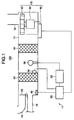
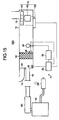
- Fig. 1 is a schematic view showing the structure of a first embodiment of an air purifying apparatus according to the present invention.
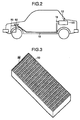
- Fig. 2 is an explanatory view showing the mounting position of the air purifying apparatus when the air purifying apparatus of the first embodiment is adapted for use in an automobile.
- Fig. 3 is a perspective view of a photocatalyst filter used in the air purifying apparatus of the first embodiment.
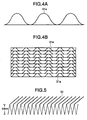
- Figs. 4(A) and 4(B) show the structure of the photocatalyst filter, in which Fig. 4(A) is a schematic view showing a filter element of the photocatalyst filter which is formed from folded thin metallic sheets and Fig. 4(B) is also a schematic view showing a filter base member of the photocatalyst filter which is formed by stucking a plurality of the filter elements together.
- Fig. 5 is a perspective view of a filter element of an adsorption filter used in the air purifying apparatus of the first embodiment.
- Fig. 6 is a schematic view of a testing apparatus used to test the removal abilities of the photocatalyst filter and the adsorption filter.
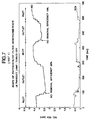
- Fig. 7 is a graph showing the results of the NO removal test 1 for the photocatalyst filter for the case in which no ultraviolet ray irradiation takes place.
- Fig. 8 is a graph showing the results of the NO removal test 2 for the photocatalyst filter for the case in which an ultraviolet ray irradiation takes place.
- Fig. 9 is a graph showing the results of the NO removal test 3 for the photocatalyst filter for the case in which a small amount of the photocatalyst is used and an ultraviolet ray irradiation takes place.
- Fig. 10 is a graph showing the results of the reactivation test for the photocatalyst filter.
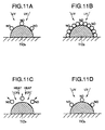
- Figs. 11(A) - 11(D) are conceptual views showing how NO is adsorbed and eliminated from the photocatalyst filter.
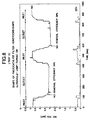
- Fig. 12 is a graph showing the results of the neutral gas adsorption test for the photocatalyst filter.
- Fig. 13 is a graph showing the results of the neutral gas adsorption test for the photocatalyst filter and the adsorption filter.
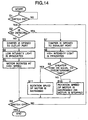
- Fig. 14 is a flow chart showing the operation of the air purifying apparatus of the first embodiment .
- Fig. 15 is a schematic view showing the structure of a second embodiment of an air purifying according to the present invention.
- Fig. 16 is a graph showing the results of an experiment for measuring changes in the surface temperature of the photocatalyst filter.
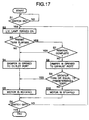
- Fig. 17 is a flow chart showing the operation of the air purifying apparatus of the second embodiment when used in an automobile.
- Fig. 18 is a schematic view showing the structure of a third embodiment of an air purifying apparatus according to the present invention.
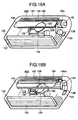
- FIGs. 19(A),(B) are perspective views of a fourth embodiment of an air purifying apparatus according to the present invention, in which Fig. 19(A) shows the state of the air purifying apparatus when it is purifying air, and Fig. 19(B) shows the state of the air purifying apparatus when it is carrying out an operation to reactivate an activated carbon filter.
- Fig. 20 is a side view showing the position where the air purifying apparatus of the fourth embodiment is mounted in an automobile.
- Fig. 21 is a flow chart showing the control operations of a control device of the fourth embodiment of the air purifying apparatus.
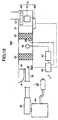
- Fig. 22 is a schematic view showing the structure of a fifth embodiment of an automobile air purifying apparatus according to the present invention.
- Fig. 23 is a side view showing the position where the air purifying apparatus of the fifth embodiment is mounted in
- Fig. 24 is a flow chart showing the main routine of a control device of the air purifying apparatus of the fifth embodiment .
- Fig. 1 shows the structure of an air purifying apparatus 100 according to the first embodiment of the present invention.
- Fig. 2 shows the mounting position of the air purifying apparatus 100 when it is adapted for use in an automobile for purifying the air inside the automobile compartment.
- the air purifying apparatus 100 is mounted inside the trunk room which is positioned at the rear side of the automobile compartment.
- the air purifying apparatus 100 has a purification passage 13 which includes an air intake port 12 for taking in air from the inside of the room or the automobile compartment, an outlet port (blow out port) 16 for blowing purified air back into the inside of the room or the automobile compartment and an exhaust port 18 which is switchable with the outlet port 16.
- the outlet port 16 and the exhaust port 18 are switched by a damper 22.
- a first adsorption means 32 constructed from a photocatalyst filter for mainly removing NOx components and organic components such as aldehydes, ammonia and the like which are odor components found in tobacco smoke and the like from the air
- a second adsorption means 30 placed at the upstream side of the first adsorption means 32.
- the second adsorption means 30 is constructed from an adsorption filter for mainly removing neutral gas from the air.
- neutral gas is used to mean any gases which are hard to be adsorbed by the photocatalyst filter 32. Examples of such gases include gases containing aromatic components or the like.
- a light source (ultraviolet ray emitting source) 58 for irradiating ultraviolet light to these filters 32, 30 for activating the photocatalyst in the photocatalyst filter 32 and heating these filters 32, 30.
- the light source 58 is constructed from an ultraviolet lamp, namely a metal halide lamp, but it is possible to use various lamps so long as they can activate the photocatalyst.
- the ultraviolet lamp 58 is constructed so as to switch between outputs of 10W and 100W by means of a controlling device 55. Further, in this embodiment, the ultraviolet lamp 58 is arranged so as to irradiate the photocatalyst at 100W in order to raise the surface temperature of the photocatalyst from 80°C to 100°C. For this purpose, in this embodiment, the ultraviolet lamp 58 is arranged at a distance of 5cm from the first adsorption means (photocatalyst filter 32).
- an air feeding means 15 is arranged in the purifying path 13 at a position upstream from the adsorption filter 30 to draw in air from the air intake port 12 and forcedly feed such air through the adsorption filter 30 and the photocatalyst filter 32.
- This air feeding means 15 is equipped with a DC motor 40, a turbo fan 42 driven by the DC motor 40, and a motor controller 45 which controls the speed of rotation of the DC motor 40 to feed a required amount of air.
- the air purifying apparatus 100 is provided with a reactivating means 17 which detects the saturated state of the photocatalyst filter 32 with the adsorbed substances and carries out a prescribed reactivation operation to reactivate the photocatalyst filter 32 when such a saturated state occurs.
- a reactivating means 17 which detects the saturated state of the photocatalyst filter 32 with the adsorbed substances and carries out a prescribed reactivation operation to reactivate the photocatalyst filter 32 when such a saturated state occurs.
- the photocatalyst filter 32 adsorbs NOx components and the like over time, the photocatalyst filter 32 eventually becomes saturated with such adsorbed substances, thereby lowering the adsorptivity of the photocatalyst filter 32.
- the air purifying apparatus 100 is provided with the reactivating means 17 for reactivating the photocatalyst filter 32.
- the reactivating means 17 also functions to reactivate the adsorption filter 30 as well.
- the reactivating means 17 is roughly constructed from a stabilizer 53 for lighting up the ultraviolet lamp 58, a temperature sensor 56 for measuring the temperature of the photocatalyst filter 32, a gas concentration sensor 46 for detecting the concentration of a prescribed gas in the air which is passed through the photocatalyst filter 32, and a control device 55 which receives signals from the temperature sensor 56 and the gas concentration sensor 46 and controls the stabilizer 53 and the motor controller 45 in response to the signals.
- the gas concentration sensor 46 is constructed into an NOx sensor to detect the concentration of NOx in the air.
- the control device 55 also controls the opening and closing of the damper 22.
- a reactivation operation of the photocatalyst filter 32 is carried out.
- the reactivation operation is carried out by adjusting the rotational speed of the DC motor 40 by means of the motor controller 45 in accordance with signals sent from the control device 55 in order to either reduce the amount of the feeding air or stop supply of such air or intermittently supply such flow of air, and/or by increasing the intensity of the ultraviolet rays emitted by the ultraviolet lamp 58 by means of the stabilizer 53, so that the surface temperature of the photocatalyst filter 32 rises to eliminate the adsorbed substances and thereby reactivate the photocatalyst filter 32.
- the detection level of the NOx sensor 46 is preferably set to match the conditions for beginning a reactivation operation.
- the damper 22 is operated in accordance with signals from the control device 55 to open the exhaust port 18, whereby exhaust containing the eliminated Nox or the like is released to the outside of the room or the automobile compartment via the exhaust port 18.
- the air purifying apparatus 100 is applied for use in an automobile as shown In Fig. 2, the NOx, HNO 3 and the like which are eliminated from the filters 32, 30 are forcedly fed to an air cleaner 62 of an engine 60, and then such eliminated (desorbed) substances undergo combustion in a combustion chamber and then they are fed to a catalytic converter rhodium 61 so as to be altered into harmless nitrogen which can safely be released into the environment outside the automobile.
- the photocatalyst filter 32 which constitutes the first adsorption means includes a porous adsorbent such as activated carbon and a photocatalyst such as TiO 2 .
- the porous adsorbent (activated carbon) is used for mainly adsorbing some odor components which are those found in tobacco smoke and which are difficult to be adsorbed by the photocatalyst in addition to Nox components except for NO.
- the photocatalyst is used for mainly adsorbing and oxidizing/decomposing NO, which is difficult to be adsorbed with activated carbon, and other organic components.
- a photocatalyst made from TiO 2 can adsorb the NO in the air, which is difficult to be adsorbed with activated carbon, and oxidize/decompose such NO into NO 2 which can be adsorbed by the activated carbon. Further, the photocatalyst is also served to oxidize and/or decompose the main components of tobacco smoke such as aldehydes, ammonia and other organic components (odor components) which are difficult to be adsorbed with the activated carbon fibers that make up the adsorption filter 30, and finally alter them into water, carbon dioxide and nitric acid. For this reason, the air purifying apparatus 100 which uses such a photocatalyst is particularly suited for use in automobiles where the air to be purified contains a high concentration of NO.
- an adsorbent made from activated carbon has excellent adsorptivity for poisonous gases such as Nox (mainly NO 2 ) excepting NO, SOx and the like.
- poisonous gases such as Nox (mainly NO 2 ) excepting NO, SOx and the like.
- silicagel, activated alumina or zeolite or a combination thereof in place of the activated carbon.
- the adsorbent and the photocatalyst may be arranged separately, but in the present embodiment the photocatalyst is carried by the activated carbon. Since the photocatalyst is carried by the activated carbon in this way, the NOx produced by being oxidized by the photocatalyst are immediately adsorbed by the activated carbon. This makes it possible to prevent the photocatalyst from being covered with such oxides, thereby enabling to to extend the life of the photocatalyst.
- the adsorbent activated carbon
- the provision of the photocatalyst together with the activated carbon makes it possible to suppress the rate at which NOx components accumulate on the activated carbon. Accordingly, there is no need to frequently carry out an operation to eliminate adsorbed substances. Further, it is also possible to avoid the characteristics of the activated carbon from being altered by high temperature of heat that is added when the elimination operation is carried out. Therefore, it becomes possible to safely use the photocatalyst filter 32 over a long period of time without replacement. As described above, by having the photocatalyst to be carried by the activated carbon 32, a synergistic effect that both improve the adsorptivity and extend the life of the photocatalyst filter can be obtained.
- TiO 2 is used as the photocatalyst, but it is possible to use various materials, so long as they can adsorb and oxidize/decompose NO and odor components mentioned above.
- the adsorbent and the photocatalyst in the photocatalyst filter 32 are provided on a metallic filter base member 33.
- the metallic filter base member 33 includes a plurality of filter elements each formed by folding thin stainless steel sheets 31a into a wave-shaped member as shown in Fig. 4(A). Then, the metallic filter base member 33 is constructed by stacking a plurality of such wave-shaped elements together, as shown in Fig. 4(B).
- a metallic filter base member 30 has excellent conductivity of heat, it is suitable for carrying out reactivation by heat. Further, when a metallic filter base member 30 is constructed as described above, it makes it possible to reduce losses in pressure, increase the surface area of the adsorbent, and achieve a very efficient ultraviolet irradiation.
- the metallic filter base member 33 was described as being constructed from thin stainless steel sheets, it is possible to construct such a metallic filter base member 30 by replacing the stainless steel sheets with thin sheets of copper, aluminum or the like folded into a pleat-like shape. Further, it is also possible to construct such a metallic filter base member 30 by folding thin sheets of stainless steel, copper, aluminum or the like into an honeycomb-shaped structure. By constructing the metallic filter member in this way, it becomes possible to further reduce losses in pressure and increase the surface area of the adsorbent, and achieve an even more efficient ultraviolet irradiation.
- a filter base member from other nonburnable materials, such as ceramic, for example.
- the photocatalyst filter 32 from a honeycomb-shaped structure formed of a mixture of titanium oxide (TiO 2 ) and activated carbon without using such a filter base member.
- a photocatalyst to be carried by other adsorbent such as activated carbon fibers, silica gel or the like.
- the photocatalyst of the photocatalyst filter 32 is activated by irradiation with ultraviolet rays emitted from the ultraviolet lamp 58, and as heating occurs, the adsorbed substances are eliminated and thereby reactivation of the photocatalyst filter 32 takes place. Therefore it becomes possible to reuse the photocatalyst repeatedly for a long time. Further, by being heated in the same way, the substances adsorbed by the activated carbon are also decomposed, so that the activated carbon is also reactivated.
- the adsorption filter 30 which constitutes the second adsorption means includes an activated carbon fiber product 31 which is fomred by folding the activated carbon fiber sheet into a pleat-shaped structure having a width and length of 200mm x 200mm and a height of 50mm.
- the activated carbon fiber product 31 strongly adsorb odors in tobacco smoke which are difficult to be adsorbed by the photocatalyst and the like. Examples of such odors include NO 2 and SOx and the like.
- the activated carbon fiber product 31 it is possible to use "Fine Guard” (registered trademark) manufactured by Toho Rayon Inc. which employees acrylic fibers as a base material.
- the characteristics of the activated carbon fiber product sold as "Fine Guard” include a specific surface area of 500 - 1200m 2 /g, an average pore diameter of 20 - 40 ⁇ m, a fiber diameter of 7 - 15 ⁇ m, a tensile strength of 20 - 50kg/mm 2 , an N content percentage of 2 - 10%, an external surface area of 0.2 - 0.7m 2 /g, and a benzene equilibrium adsorption of 20 - 50%.
- the felt-shaped FE-200 (roughness of mesh is 100g/m 2 ) is used by folding it into a pleat-shaped structure.
- the activated carbon fiber product 31 is also heated by the ultraviolet rays from the ultraviolet lamp 58, thereby eliminating the adsorbed substances to reactivate the activated carbon fiber product 31, thus making it possible to reuse the activated carbon fiber product 31 repeatedly.
- the adsorption filter 30 and the photocatalyst filter 32 may be provided in the purification passage 13 in such a way as to be removable therefrom.
- FIG. 6 shows the testing apparatus used to test the ability of a photocatalyst filter at removing NOx especially NO.
- This testing apparatus draws in air containing NO gas from an intake port 62, and forcedly feeds such air to a column 66 by means of a turbo blower 64.
- a photocatalyst filter 72 is arranged downstream from the column 66, and an ultraviolet lamp (sterilizing lamp) 68 for irradiating the photocatalyst filter 72 with ultraviolet rays is arranged inside the column 66.
- an ultraviolet lamp (sterilizing lamp) 68 for irradiating the photocatalyst filter 72 with ultraviolet rays is arranged inside the column 66.
- an aluminum foil shield is provided on the inner circumferential surface of the column 66.
- a stabilizer 78 which supplies power at 100V AC to the ultraviolet lamp 68.
- NOx concentration measuring meter 74 is connected to the inlet and the outlet of the column 66 via valves 74a, 74b,
- the photocatalyst filter 72 also includes TiO 2 (photocatalyst) and activated carbon in the same manner as that of the photocatalyst filter 32 of the first embodiment.
- TiO 2 photocatalyst
- activated carbon in the same manner as that of the photocatalyst filter 32 of the first embodiment.
- a mixture of TiO 2 and activated carbon is formed into a honeycomb-shaped structure to form the photocatalyst filter 72.
- the NO concentration was alternately measured at the inlet of the column 66 (i.e., at a position upstream from the photocatalyst filter 72) and at the outlet of the column 66 (i.e., at a position downstream from the photocatalyst filter 72). These measurements were carried out at a flow rate of 3 liters/minute.
- the NO concentration at the inlet after 80 seconds was 4.4ppm, and the NO concentration at the outlet after 100 seconds was 3.1ppm, which shows an initial NO removal efficiency of 29%.
- the adsorptivity of the photocatalyst filter 72 went down. Namely, the NO concentration at the inlet after 400 seconds was 4.5ppm and the NO concentration at the outlet after 430 seconds was 3.7ppm, which shows a drop in NO removal efficiency to 18%.
- the results of this experiment show that the photocatalyst filter 72 can adsorb NO even when the photocatalyst filter 72 is not being irradiated with ultraviolet rays, but that the photocatalyst filter under this condition is saturated in a short time.
- NO 2 is also generated due to oxidation of NO, but such NO 2 is removed by the activated carbon contained in the photocatalyst filter 72.
- the results of this experiment show that the photocatalyst filter 72 can continue to adsorb NO over a relatively long period of time when irradiated with ultraviolet rays. This is because NO is removed by photocatalytic reaction caused by the irradiation of the ultraviolet rays. Further, NO2 is also removed by adsorbing ability of the activated carbon in the same manner as is the case shown in Fig. 7.
- Fig. 11(A) before the photocatalyst comprised of TiO 2 adsorbs a large amount of NO, the surface thereof is directly irradiated with ultraviolet rays, and this makes it possible for the photocatalyst TiO 2 to have a relatively high effectiveness at adsorbing and oxidizing NO,
- the photocatalyst TiO 2 becomes covered with NO molecules, as shown in Fig. 11(B), and this makes it difficult for the ultraviolet rays to reach the surface of the photocatalyst.
- the photocatalytic reactions are slowed down, and in this state the effect of reactivation is low even when irradiated with ultraviolet rays.
- Fig. 12 is a graph which shows the results of the neutral gas adsorption test which was carried out using the photocatalyst filter 72 described above with reference to Figs. 6 - 10 alone.
- an aromatic substance sold for household use was used as the neutral gas.
- measurements were alternately carried out at the outlet and the inlet, wherein the neutral gas concentration is plotted on the vertical axis and elapsed time is plotted on the horizontal axis.
- the photocatalyst filter 72 which uses TiO 2 adsorbed hardly any neutral gas.
- Fig. 13 is a graph which shows the result of the other neutral gas adsorption test which was carried out using an adsorption filter in addition to the photocatalyst filter 72.
- the adsorption filter is arranged upstream from the photocatalyst filter 72 and it is constructed from activated carbon fibers so as to be essentially the same as the adsorption filter 30 described above.
- the measurement results clearly show different concentrations at the inlet and the outlet, which shows that the adsorption filter can remove such neutral gas.
- Step 2 the process proceeds to Step 3 (S3) where the control device 55 of the air purifying apparatus 100 carries out an operation to open the damper 22 to the outlet port 16 so as to be able to blow purified air into the inside of the room or the automobile compartment.
- Step 4 the ultraviolet lamp 58 is operated at the relatively low output of 10W to irradiate the adsorption filter 30 and the photocatalyst filter 32 with the relatively low intensity ultraviolet rays.
- Step 5 the DC motor 40 is operated at high speed to begin forcedly feeding of air which is taken in from the air intake port 12 toward the adsorption filter 30.
- the air which is taken in from the inside of the room or the automobile compartment is forcedly fed so as to pass through the adsorption filter 30 to remove neutral gases contained in the air as was described above with reference to Fig. 13.
- the feeding air also passes through the photocatalyst filter 32, where NO and other NOx components are adsorbed and removed by the photocatalyst filter 32, and then the air which has thus purified is blown back into the inside of the room or the automobile compartment. This purifying operation continues until the starter switch is turned off (i.e., a "Yes" determination at S6).
- Step 2 the NOx sensor 46 detects NOx, whereupon a "Yes" determination is made at Step 2 (S2), and then the process proceeds to Step 7 (S7) to begin an operation to eliminate adsorbed substances (i.e., to reactivate the photocatalyst filter 32).
- Step 7 the damper 22 is opened to the exhaust port 18 to enable exhaust containing the eliminated (desorbed) substances to be released to the outside of the room or the automobile compartment (S7).
- Step 8 by means of a signal sent from the control device 55, the ultraviolet lamp 58 is operated at the relatively high output of 100W to irradiate the adsorption filter 30 and the photocatalyst filter 32 with the relatively high intensity ultraviolet light.
- the temperature sensor 56 is used to determine whether or not the surface temperature of the photocatalyst filter 32 is greater than or equal to a prescribed temperature value (e.g., 80°C).
- a prescribed temperature value e.g. 80°C
- the process proceeds to Step 10 (S10) in which the DC motor 40 is either stopped or the rotation speed thereof is reduced.
- the prescribed temperature value may lie in the range 80°C - 100°C.
- Step 9 a "Yes" determination is made at Step 9 (i.e., it is determined that the temperature exceeds the prescribed temperature value) and the process proceeds to Step 11 (S11), and then the DC motor 40 is operated at high speed to lower the temperature of the photocatalyst filter 32 to 80°C.
- Steps 9, 10 and 11 the rotational speed of the DC motor 40 is changed to adjust the amount of the feeding air, thereby maintaining the surface temperature of the photocatalyst filter 32 at 80°C. This makes it possible to continuously eliminate adsorbed substances from the photocatalyst under the appropriate temperature.
- Step 2 the concentration of NOx has been lowered
- Step 3 Step 3
- the photocatalyst and the activated carbon are used with being reactivated by eliminating adsorbed substances therefrom, the photocatalyst and the activated carbon can continuously purify air over a long period of time without the need for replacement. Furthermore, because high heat is not required at the time when an operation for eliminating adsorbed substances is carried out, there is no deterioration of the photocatalyst and the activated carbon. Further, no special heating device is required when carrying out an operation to eliminate adsorbed substances from the photocatalyst and the activated carbon. Further, because the ultraviolet lamp 58 is operated at a low power output of 10W when not carrying out a reactivation operation, the air purifying apparatus according to this embodiment is quite economical with regards to power consumption.
- the first adsorption means photocatalyst filter 32 in the embodiment above from just an adsorbent made from activated carbon without using any photocatalyst.
- the adsorptivity of the adsorbent goes down, it is also possible to heat and reactivate the adsorbent in the same way by irradiating the adsorbent with ultraviolet rays emitted from an ultraviolet lamp and adjusting the amount of the feeding air by the air feeding means (i.e., by reducing the rotational speed of the motor, by stopping the motor, or by intermittently carrying out air feeding).
- the amount of the feeding air by the air feeding means can be used to adjust and maintain the raised temperature at a prescribed temperature suited for reactivation of the activated carbon, thus making it possible to effectively reactivate the activated carbon without altering its characteristics.
- a heating means such as a heater or the like to heat the activated carbon instead of the ultraviolet lamp, and to maintain a prescribed raised temperature suited for reactivation for the activated carbon by adjusting the amount of the feeding air by the air feeding means.
- Fig. 15 shows the structure of the air purifying apparatus 200 or the second embodiment.
- this air purifying apparatus 200 When this air purifying apparatus 200 is applied for an automobile, it is mounted above a trunk room positioned at the rear side of an automobile compartment and an exhaust port 18 thereof is coupled to an air cleaner 62 of an engine 60 as described hereinbelow as shown in Fig. 2.
- the air purifying apparatus 200 of the second embodiment has substantially the same structures as those of the air purifying apparatus 100 of the first embodiment excepting that only one adsorbing means which is constructed from a photocatalyst filter 32 is used and a light source (ultraviolet lamp) is constructed so as not to be able to change the intensity of light emitting therefrom. Therefore, the same reference numerals as those in the first embodiment are used to designate the same or corresponding components or parts.
- the air purifying apparatus 200 has a purification passage 13 which includes an air intake port 12 for taking in air from the the inside of the room or the automobile compartment, an outlet port (blow out port) 16 for blowing purified air back into the inside of the room or the automobile compartment and an exhaust port 18 which is switchable with the outlet port 16.
- the outlet port 16 and the exhaust port 18 are switched by a damper 22.
- This exhaust port 18 is coupled to the cleaner 62 of the engine 60 when the air purifying apparatus 200 is adapted for use in an automobile.
- an adsorption means 32 constructed from a photocatalyst filter.
- the photocatalyst filter 32 is provided with a porous adsorbent such as activated carbon for mainly adsorbing odor components such as those found in tobacco smoke and the like as well as other odor components such as NOx excepting than NO, and a photocatalyst such as TiO 2 for adsorbing and oxidizing/decomposing NO and other organic substances which are difficult to be adsorbed by the activated carbon. Since the details of the activated carbon and the photocatalyst are the same as those of the photocatalyst filter 32 of the first embodiment, further explanations are omitted.
- a light source (ultraviolet ray emitting source) 58 for irradiating ultraviolet rays to the photocatalyst filter 32 for activating and heating the photocatalyst in the photocatalyst filter 32.
- the light source 58 is constructed from an ultraviolet lamp, namely a metal halide lamp. This ultraviolet lamp 58 is constructed and arranged in the same manner as the ultraviolet lamp 58 of the first embodiment excepting that it can not change the intensity of ultravioket rays emitting therefrom.
- an air feeding means 15 is arranged in the purifying path 13 at a position upstream from the photocatalyst filter 32 to draw in air from the air intake port 12 and forcedly feed such air through the photocatalyst filter 32.
- this air feeding means 15 is equipped with a DC motor 40, a turbo fan 42 driven by the DC motor 40, and a motor controller 45 which controls the speed of rotation of the DC motor 40 to feed a required amount of air.
- the air purifying apparatus 200 is provided with a reactivating means 17 which detects the saturated state of the photocatalyst filter 32 with the adsorbed substances and carries out a prescribed reactivation operation to reactivate the photocatalyst filter 32 when such a saturated state occurs. Namely, the adsorptivity of the photocatalyst filter 32 becomes lowered if the photocatalyst filter 32 continues to adsorb NOx components and the like over time. For this reason, the air purifying apparatus 200 of the second embodiment is also provided with a reactivating means 17 for the photocatalyst filter 32.
- this reactivating means 17 is operated so as to reduce the amount of the feeding air or stop the supply of the feeding air to rise the temperature of the photocatalyst filter 32 so that the adsorbed substances be eliminated from the photocatalyst and activated carbon, when the adsorptivity of the photocatalyst filter 32 is lowered and thereby a reactivation of the photocatalyst filter 32 becomes necessary.
- the reactivating means 17 is roughly constructed from a stabilizer 53 for lighting up the ultraviolet lamp 58, a temperature sensor 56 for measuring the temperature of the photocatalyst filter 32, a NOx sensor 46 for detecting the concentration of NOx in the air which is passed through the photocatalyst filter 32, and a control device 55 which receives signals from the temperature sensor 56 and the NOx sensor 46 and controls the stabilizer 53 and the motor controller 45 in response to the received signals. Further, the control device 55 also controls the opening and closing of the damper 22.
- a reactivation operation of the photocatalyst filter 32 is carried out.
- the reactivation operation is carried out by adjusting the speed of the DC motor 40 by means of the motor controller 45 in accordance with signals sent from the control device 55 in order to either reduce the amount of the feeding air or stop the supply of such feeding air or intermittently supply of such feeding air.
- the surface temperature of the photocatalyst filter 32 is raised by the irradiation of ultraviolet rays emitted from the ultraviolet lamp 58 to activate the photocatalyst so that oxidization and decomposition by the photocatalyst are promoted and the adsorbed substances are eliminated to reactivate its adsorptivity. Further, the odor components such as NOx or the like which have been adsorbed by the reactivated carbon are also eliminated.
- the damper 22 When such an eliminating operation is carried out, the damper 22 is operated to open, and the NOx, HNO 3 and the like which have been eliminated from the photocatalyst and the activated carbon are forcedly fed to the air cleaner 62 of the engine 60, and then such substances undergo combustion in a combustion chamber and then they are fed to a catalytic converter rhodium 61 so as to be altered into harmless nitrogen which can safely be released into the environment outside the automobile.
- the photocatalyst filter 32 is constructed so as to be reactivated with the ultraviolet rays from the ultraviolet lamp 58 by adjusting the amount of the feeding air from the air feeding means 15 ((i.e., by reducing the rotational speed of the motor, by stopping the motor, or by intermittently carrying out such air feeding) in the case where the adsorptivity of the photocatalyst 32 is lowered due to the saturation by the adsorbed substances.
- Fig. 16 is a graph which shows changes in the temperature at the surface of the photocatalyst filter 32 over time, when the feeding of the air has been stopped or interrupted to prevent the photocatalyst filter 32 from cooling under the condition that the photocatalyst filter 32 is irradiated with ultraviolet light emitted from the ultraviolet lamp 58.
- the temperature at the surface of the photocatalyst filter 32 rises from 25°C at the moment when the feeding of air is stopped to 80°C after 500 seconds have elapsed.
- the photocatalyst filter 32 is heated only by adjusting the amount of the feeding air with maintaining the intensity of the ultrabiolet rays emitted from the ultraviolet lamp 58 at an output of 100W.
- the control device 55 of the automobile air purifying apparatus 200 lights up the ultraviolet lamp 58 to irradiate the photocatalyst filter 32 with ultrabiolet rays (step S2).
- the control device 55 determines whether or not a predetermined amount of time (e.g., 10 hours of total usage) has elapsed since the last time when an elimination process was performed to eliminate adsorbed substances by the photocatalyst filter (step S3).
- step S3 if it is determined that a predetermined amount of time has not yet elapsed (i.e. a "No" determination at step S3), an operation to purify the air in the inside of the room or the automobile compartment is begun.
- the damper 22 is operated to open the outlet port 16 so as to be able to blow purified air into the inside of the room or the automobile compartment (step S4).
- the DC motor 40 is turned on to begin taking in air from the inside of the room or the automobile compartment (step S5).
- the air which is taken in from the inside of the room or the automobile compartment is fed to the photocatalyst filter 32 to pass therethrough, where the photocatalyst adsorbs and oxidize/decompose NO in the air while oxidize and decompose other odor components such as aldehydes and ammonia and the activated carbon adsorbs NOx or the like.
- the air is purified and then blown back into the inside of the room or the automobile compartment. This purification operation will continue until the starter switch is turned off (i.e., a "Yes" determination at step S6).
- step S3 determines whether a predetermined amount of time has elapsed since the last reactivation operation of the photocatalyst filter 32 (i.e., a "Yes" determination at step S3).
- an elimination process to eliminate adsorbed substances that is a reactivation of the photocatalyst filter 32 is begun.
- the damper 22 is operated to open the exhaust port 18 which communicates with the air cleaner 62 of the engine 60 in order to allow exhaust containing the eliminated substances and the like to be sent to the engine 60 (step S8).
- step 9 S9 to determined as to whether or not the temperature at the surface of the photocatalyst filter 32 exceeds a predetermined temperature (e.g. 80°C).
- a predetermined temperature e.g. 80°C.
- the temperature at the surface of the photocatalyst filter 32 rises approximately to the predetermined temperature of 80°C, which activates the photocatalyst and then oxidizes and decomposes the NO or the like which have been adsorbed by the photocatalyst filter 32 to eliminate them from the photocatalyst filter 32.
- the activated carbon is also heated, thereby the adsorbed substances such as NOx and the like are also eliminated from the activated carbon.
- step S9 the process moves to step S5 where the DC motor 40 is turned on to cool the surface of the photocatalyst filter 32 so as to be less than 80°C.
- the DC motor 40 is intermittently operated to maintain the temperature of the photocatalyst filter 32 at a 80°C, thereby eliminating the adsorbed substances from the photocatalyst filter 32 to reactivate it under the appropriate condition.
- the photocatalyst filter 32 is heated by intermittently stopping the supply of the feeding air when the photocatalyst filter 32 is reactivated.
- Fig. 18 shows the structure of an automobile air purifying apparatus 300 according to the third embodiment of the present invention.
- the air purifying apparatus of this third embodiment are different from that of the second embodiment only in the following points.
- the operation of the air purifying apparatus 300 of this embodiment is substantially the same as that of the first embodiment which has been described with reference to the flow chart shown in Fig. 14.
- Step 2 when a starter switch (not shown in the drawings) is turned on (i.e., a "Yes" determination at S1), the process proceeds to step 2(S2).
- step 2 (S2) if a "No" determination is made, the process proceeds to Step 3 (S3) where the control device 55 of the air purifying apparatus 100 carries out an operation to open the damper 22 to the outlet port 16 so as to be able to blow purified air into the inside of the room or the automobile compartment.
- Step 4 the ultraviolet lamp 58 is operated at the relatively low output of 10W to irradiate the photocatalyst filters 32, 32 with the relatively low intensity ultrabiolet rays.
- Step 5 the DC motor 40 is operated at high speed to begin forcedly feeding air which is taken in from the air intake port 12 toward the photocatalyst filters 32, 32.
- the air which is taken in from the inside of the room or the automobile compartment is forcedly fed so as to pass through the photocatalyst filters 32, 32, where NO and other NOx components are adsorbed and removed by the photocatalyst filters 32, 32, and then the air which has been purified is blown back into the inside of the room or the automobile compartment.
- This purifying operation continues until the starter switch is turned off (i.e., a "Yes" determination at S6).
- Step 2 the NOx sensor 46 detects NOx, whereupon a "Yes" determination is made at Step 2 (S2), and then the process proceeds to Step 7 (S7) to begin an operation to eliminate adsorbed substances (i.e., to reactivate the photocatalyst filters 32, 32).
- Step 7 the damper 22 is opened to the exhaust port 18 so as to be able to release exhaust containing the eliminated (desorbed) substances to the outside of the room or the automobile compartment (S7).
- Step 8 by means of a signal from the control device 55, the ultraviolet lamp 58 is operated at the relatively high output of 100W to irradiate the photocatalyst filters 32, 32 with the relatively high intensity ultraviolet light.
- the temperature sensor 56 is used to determine whether or not the surface temperature of the photocatalyst filter 32 is greater than or equal to a prescribed temperature value (e.g., 80°C).
- a prescribed temperature value e.g. 80°C
- the process proceeds to Step 10 (S10) where the DC motor 40 is either stopped or the rotation speed thereof is reduced.
- the prescribed temperature value may lie in the range 80°C - 100°C.
- Step 11 the process proceeds to Step 11 (S11), where the DC motor 40 is operated at high speed to lower the temperature of the photocatalyst filters 32, 32 to 80°C.
- Steps 9, 10 and 11 the rotational speed of the DC motor 40 is changed to adjust the amount of the feeding air, thereby maintaining the surface temperature of the photocatalyst filters 32, 32 at 80°C. This makes it possible to continuously eliminate adsorbed substances from the photocatalyst under the appropriate temperature.
- Step 2 Step 2
- Step 3 Step 3
- the NOx elimination capacity is improved rather than that of the second embodiment.
- the heating up of the photocatalyst filters 32, 32 can be made in a relatively short amount of time, thereby enabling to complete elimination of the odor components such as NOx from the photocatalyst and the activated carbon in a short amount of time.
- the adsorption means photocatalyst filter 32
- the adsorption means photocatalyst filter 32
- the adsorptivity of the adsorbent goes down, it is also possible to heat and reactivate the adsorbent in the same way by irradiating the adsorbent with ultrabiolet rays from an ultraviolet lamp and adjusting the amount of the feeding air by the air feeding means (i.e., by reducing the rotational speed of the motor, by stopping the motor, or by intermittently carrying out air feeding).
- the amount of the feeding air by the air feeding means can be used to adjust and maintain the raised temperature at a prescribed temperature suited for reactivation of the activated carbon, thus making it possible to effectively reactivate the activated carbon without altering its characteristics.
- a heating means such as a heater or the like to heat the activated carbon instead of the ultraviolet lamp, and to maintain a prescribed raised temperature suited for reactivation for the activated carbon by adjusting the amount of the feeding air by the air feeding means.
- the feature of the air purifying apparatus 400 of this fourth embodiment resides in that an adsorbent such as activated carbon is heat reactivated under the reduced pressure.
- an adsorbent such as activated carbon
- the negative pressure generated by the motion of the automobile is utilized to reduce the pressure in the purification passage where the adsorbent is arranged. For this reason, there is no need for a powerful fan motor and the large amount of power required for driving such a fan motor in order to reduce the pressure inside the air purifying apparatus. Further, this makes it possible to construct a relatively compact air purifying apparatus which can efficiently eliminate adsorbed substances.
- FIG. 19 The structure of this fourth embodiment of an air purifying apparatus 400 is shown in Figs. 19 (A) and (B). Further, Fig. 20 shows the mounting position of the air purifying apparatus 400 in an automobile 401 when the air purifying apparatus 400 is adapted for use as an automobile air purifying apparatus.
- the air purifying apparatus 400 is mounted on a rear shelf 404 which separates an automobile compartment 402A of the automobile 401 from a trunk room 403.
- this air purifying apparatus utilizes a negative pressure which is created in the trunk room 403 when the automobile is in motion.
- the trunk room 403 constitutes a portion of the ventilation system which creates such an negative pressure and expels exhaust air inside the automobile to the outside of the automobile.
- the reference numeral 404a shows an opening which is formed in the rear shelf.
- Fig. 19(A) shows the state of the air purifying apparatus 400 when it is purifying air
- Fig. 19(B) shows the state of the air purifying apparatus 400 when it is carrying out an operation to reactivate the activated carbon filter 124.
- the air purifying apparatus 400 includes an air intake port 122 comprised of slits formed in the front portion of a housing 120, an outlet port (blow out port) 134 comprised of slits provided in the upper portion of the housing 120 for blowing out purified air, and an exhaust port 128 for expelling exhaust to the trunk room 403 through the opening 404a.
- the space inside the housing 120 which runs from the air intake port 122 to the outlet port 134 or to the exhaust port 128 constitutes a purification passage 113.
- a shutter 136 for opening and closing the outlet port 134 is provided in the upper portion of the housing 120, and outlet port opening-closing device (lever) 138 for opening and closing the shutter 136 is provided at a side portion of the housing 120.
- a first adsorption means comprised of a cartridge-type activated carbon filter 124 removably arranged at the air intake port 122; a fan 140 for expelling air which has been taken in from the air intake port 122 and purified by the activated carbon filter 124 out through the outlet port 134, the blades of the fan 140 having a photocatalyst which forms a second adsorption means; an ultraviolet lamp 126 for irradiating and heating the activated carbon filter 124 and the photocatalyst of the fan 140; and a control device for controlling the exhaust port opening-closing device 132 and the outlet port opening-closing device 138.
- the activated carbon filter (first adsorption means) 124 functions to mainly adsorb NOx, except for NO, in addition to adsorbing odor components in tobacco smoke and the like.
- the photocatalyst (second adsorption means) provided on the blades of the fan 140 functions, when it is activated by ultrabiolet rays emitted from the ultraviolet lamp 126, to adsorb and oxidize/decompose NO, which is difficult to be adsorbed by the activated carbon, and oxidize/decompose the main components of tobacco smoke such as aldehydes, ammonia and the like, into water, carbon dioxide and nitric acid by means of photocatalytic reactions.
- the fan 140 is driven by a motor not shown in the drawings.
- the exhaust port opening-closing device 132 and the outlet port opening-closing device (lever) 138 are operated to close the lid 130 and open the shutter 136.
- the fan 140 is driven to take air in from the intake port 122, such air enters the purification passage 113 through the activated carbon 124.
- Such air is purified by the activated carbon filter 124 and the photocatalyst provided on the blades of the fan 140 when the air flows in the purification passage 113. Then, thus purified air is expelled from the outlet port 134 into the inside of the automobile compartment.
- Fig. 19(B) when an adsorption means reactivation operation is to be carried out, the shutter 136 is closed to stop air from flowing out from the outlet port 134, and the exhaust port opening-closing device 132 is operated to open the lid (check valve) 130 in order to open the exhaust port 128, whereby the housing 120 establishes communication with the trunk room 403 through the opening 404a to generate a negative pressure inside the housing 120 (that is, inside the purification passage 113).
- the activated carbon filter 124 and the photocatalyst provided on the blades of the fan 140 are irradiated and heated with ultrabiolet rays emitted from the ultraviolet lamp 126 to eliminate the adsorbed substances such as NOx and the like. Then, exhaust containing such eliminated (desorbed) substances is expelled via the trunk room 403 to the outside of the automobile compartment.
- the activated carbon and the photocatalyst are heat reactivated under the reduced pressure created by utilizing the negative pressure generated in the trunk room 403.
- a negative pressure is created in the trunk room 403 only when the automobile is travelling above a prescribed speed.
- the air purifying apparatus is controlled so that the reactivation operation shown in Fig. 19(B) is carried out only when the automobile is travelling at such prescribed speed.
- Step 12 the control device 125 (which constitutes a reactivating means in this embodiment) carries out a judgement to determine whether or not a starter switch (not shown in the drawings) provided in the drivers instrument panel has been turned on. At this point, if it is determined that the starter switch is "On", the process proceeds to Step 14 (S14) where a judgement is carried out to determine whether or not the activated carbon needs to be reactivated.
- the control device 125 accumulates the operating time of the activated carbon filter 124, and therefor at this step, a reactivation operation is judged to be necessary by the control device 125 when the operating time calculated for the activated carbon filter 124 reaches a prescribed value (e.g., 100 seconds). At this point, if a determination that a reactivation operation is not necessary is made (i.e., a "No" judgement is made at S14), an air purification operation is begun. Therefore, this case will be described first hereinbelow.
- Step 16 the exhaust port opening-closing device 132 is operated to close the exhaust port 128 with the lid (check valve) 130 to prevent purified air from escaping into the trunk room 403.
- Step 18 the outlet port opening-closing device 138 is operated to open the outlet port 134 with the shutter 136.
- the ultraviolet lamp 126 is lit up to activate the photocatalyst provided on the fan 140 and the fan 140 is driven to take in air from the air intake port 122, whereupon NOx and the like in the air are adsorbed by the activated carbon filter 124 and NO, aldehydes, ammonia and the like in the air are adsorbed and oxidized/decomposed by the photocatalyst provided on the blades of the fan 140, thereby purifying the air.
- purified air is then expelled out through the outlet port 134 into the automobile compartment.
- Step 24 a judgement is carried out to determine whether or not the starter switch is "Off". In this case, so long as the starter switch is not "Off” (i.e., a "No” judgement at S24), the process returns to S14 and the purification operation described above is repeated. On the other hand, if it is determined that the starter switch is "Off” (i.e., a "Yes” judgement at S24), the process proceeds to Steps 26 and 28 (S26 & S28) where the ultraviolet lamp 126 and the fan 140 are turned off to terminate the purification operation.
- Step 30 a judgement is carried out to determine whether or not the speed of the automobile exceeds a first prescribed speed value (e.g., 40km/hr).
- a first prescribed speed value e.g. 40km/hr.
- the air purifying apparatus is provided with a speed sensor (not shown in the drawing) for measuring the speed of the automobile and output signals to the control device 125.
- the output from a speed meter installed in the automobile can be utilized instead of such a speed sensor.
- Step 32 a judgement is carried out to determine whether or not the speed of the automobile continues to stay above the first prescribed speed value over a prescribed period of time (e.g., 10 seconds).
- the air purifying apparatus 400 because the negative pressure generated in the trunk room 403 during motion of the automobile is used when carrying out an operation to reactivate the activated carbon filter 124, judgements are carried out to determine first whether or not the speed of the automobile exceeds the speed necessary for generating a negative pressure, and then whether or not the speed of the automobile continues to stay above such necessary speed to avoid situations in which the speed of the automobile is going up and down such as in a traffic jam when the automobile is continually advancing and stopping. This determination concerning the speed of the automobile is carried out based on the output of the speed sensor.
- Step 34 the control device 125 operates the outlet port opening-closing device 138 to close the outlet port 134 with the shutter 136 to stop air from flowing out from the outlet port 134.
- Steps 36 and 38 the exhaust port opening-closing device 132 is operated to open the lid (check valve) 130 in order to open the exhaust port 128, whereby the housing 120 establishes communication with the trunk room 403, and the fan 140 is turned off. In this state, a negative pressure is generated in the purification passage 113 inside the housing 120.
- the activated carbon filter 124 and the photocatalyst provided on the blades of the fan 140 are irradiated and heated under the reduced pressure conditions with ultrabiolet rays from the ultraviolet lamp 126 to eliminate adsorbed substances such as NOx and the like. Then, the exhaust containing such eliminated substances is expelled via the trunk room 403 to the outside of the automobile.
- Step 40 a judgement is carried out to determine whether or not the reactivation operating time has reached a prescribed reactivation time.
- the process proceeds to S16 and the activated carbon filter 124 and the photocatalyst provided on the blades of the fan 140 are once again used to purify air.
- the judgement at Step 40 (S40) is "No”
- the process proceeds to Step 42 (S42).
- a judgement is carried out to determine whether or not the speed of the automobile has fallen below a second prescribed speed value (which is lower than the first prescribed speed value; e.g., 35km/hr).
- Step 44 a judgement is carried out to determine whether or not the speed of the automobile remains below the second prescribed speed value for a prescribed period of time. At this step, so long as the speed of the automobile does not remain below the second prescribed speed value for the prescribed period of time (i.e., a "No" judgement at S44), the process returns to S40 and the reactivation process is continued.
- the exhaust generated during the reactivation operation is expelled to the outside of the automobile via the trunk room 403.
- this air purifying apparatus 400 is installed in the automobile, such installation is easily carried out because there is no need to provide a separate exhaust pipe to expel the exhaust created during a reactivation operation.
- the reactivation of the activated carbon filter 124 is carried out under the reduced pressure which is created by utilizing the negative pressure generated in the automobile, it is possible to perform the elimination of the adsorbed substances effectively when carrying out a reactivation operation. Further, since the photocatalyst is provided on the blades of the fan 140 and the air that has taken in is agitated by such blades having the photocatalyst inside the housing 120, it is possible to efficiently oxidize/decompose aldehydes, ammonia and the like by the photocatalyst.
- an ultraviolet lamp 126 was used in the fourth embodiment to heat the activated carbon filter 124, it is of course possible to do away with the photocatalyst provided on the fan 140 and employ a heating means such as a heater or the like instead of the ultraviolet lamp. In this case, it is also possible to carry out an efficient reactivation operation by heat reactivating the activated carbon under reduced pressure.
- Fig. 22 shows the structure of an air purifying apparatus 500 according to the fifth embodiment
- Fig. 23 shows the mounting position of the air purifying apparatus 500 in an automobile when the air purifying apparatus 500 is adapted for use as an automobile air purifying apparatus.
- the air purifying apparatus 500 is provided inside a trunk room 503.
- the air purifying apparatus 500 includes an exhaust pipe 152 which extends to the outside of the automobile, and an air intake pipe 156 and an outlet pipe 154 which communicate with the inside of the automobile. Further, an opening 152a which is formed in the exhaust pipe 152 is arranged at a position behind the rear windshield where a high negative pressure is generated.
- the air purifying apparatus 500 has a purification passage 153 which includes the air intake pipe (air intake port) 156 for taking in air from the inside of the automobile compartment, the outlet pipe (outlet port) 154 for blowing purified air back into the inside of the automobile compartment, and the exhaust pipe (exhaust port) 152 for discharging exhaust containing the eliminated adsorbed substances. Further, a damper 162 is provided to open and close the air intake port 156, and a damper 161 is provided to make it possible to switch the purification passage 153 between the outlet port 154 and the exhaust port 152.
- the exhaust pipe 152 is disposed in a negative pressure environment as described above, the opening 152a of the exhaust pipe 152 is arranged behind the rear windshield at a position where a high negative pressure is generated as described above.
- the exhaust pipe 152 it is also possible to have the exhaust pipe 152 connected to the trunk room 503 in the same manner as described in the fourth embodiment.
- the air purifying apparatus 500 is used for purifying the air in a room, it is possible to connect the exhaust pipe 152 to any appropriate pressure reducing device.
- a first adsorption means 182 comprised of a photocatalyst filter for mainly removing NOx components and the odor components in tobacco smoke and the like such as aldehydes, ammonia and the like
- a second adsorption means 180 arranged at a prescribed distance upstream from the first adsorption means 182 (toward the air intake port 156) and comprised of an adsorption filter containing a CO oxidation catalyst for mainly oxidizing CO into CO 2 .
- These first and second adsorption means 180, 182 provided in such a way as to be freely removable from the purification passage 153.
- the first adsorbing means (photocatalyst filter) 182 has a metallic filter member provided with activated carbon and a photocatalyst.
- the activated carbon function to mainly adsorb odor components such as NOx compounds and the like, except for NO, in addition to adsorbing odor components such as tobacco smoke and the like, while the photocatalyst functions to adsorb and oxidize/decompose NO which are difficult to be adsorbed with activated carbon and to oxidize and/or decompose aldehydes, ammonia and the like.
- the photocatalyst of the fifth embodiment is carried by the activated carbon.
- this photocatalyst also acts to oxidize NO into NOx which can easily be adsorbed by the activated carbon. Further, because the photocatalyst is carried by the activated carbon in the photocatalyst filter 182, the NOx adsorbed by the activated carbon is further oxidized and/or decomposed into substances such as HNO3 and the like, it is possible to slow down the rate at which NOx accumulates on the activated carbon. Moreover, because the photocatalyst can oxidize/decompose various other organic compounds (i.e., odor components other than NOx) present in the air inside and outside the automobile, it is possible to also slow down the accumulation rate of such organic substances. Further, it is also possible to oxidize/decompose such organic substances that are adsorbed by the activated carbon.
- the photocatalyst can oxidize/decompose various other organic compounds (i.e., odor components other than NOx) present in the air inside and outside the automobile, it is possible to also
- the CO oxidation catalyst used in the second adsorption means 180 is formed from a carrier such as activated carbon fibers or aluminum and a precious metal oxidation catalyst such as Pd or the like for oxidizing CO into CO2, in which the precious metal oxidation catalyst is carried by the carrier.
- a light source (ultraviolet ray emitting source) 178 for irradiating and, when necessary, heating the photocatalyst filter (first adsorption means) 182 with ultraviolet rays is provided downstream from the photocatalyst filter 182.
- the light source 178 is constructed from an ultraviolet lamp, namely a metal halide lamp, but it is possible to use various lamps so long as they can activate the photocatalyst.
- the ultraviolet lamp 178 switches between outputs of 10W and 100W by means of a controlling device 170.
- the ultraviolet lamp 178 is arranged so as to irradiate the photocatalyst at 100W in order to raise the surface temperature of the photocatalyst from 80°C to 100°C; namely, the ultraviolet lamp 178 is arranged at a distance of 5cm from the first adsorption means (photocatalyst filter) 182.
- an air feeding means 190 is arranged in the purification passage 153 at a position downstream from the first adsorption means (photocatalyst filter) 182 to draw in air from the air intake port 156 and forcedly feed such air through the first and second adsorption means 182, 180 toward either the outlet pipe 154 or the exhaust pipe 152.
- This air feeding means 190 is equipped with a DC motor 191, a turbo fan 192 driven by the DC motor 191, and a motor controller 194 which controls the speed of rotation of the DC motor 191 to feed a required amount of air.
- the air purifying apparatus 500 is provided with a reactivating means 177 which detects the saturated state of the photocatalyst filter 182 with adsorbed substances.
- the reactivating means 177 carries out a prescribed reactivation operation to reactivate the photocatalyst filter 182 when such a saturated state of the photocatalyst filter 182 occurs. Namely, when the photocatalyst filter 32 continues to adsorb Nox components and the like over time even though decomposing them, it becomes saturated with such adsorbed substances, whereby the adsorptivity of the photocatalyst filter 182 becomes lower. For this reason, in this fifth embodiment, the air purifying apparatus 500 is provided with a reactivating means 177 for the photocatalyst filter 182.
- This reactivating means 177 is roughly constructed from a stabilizer 175 for lighting up the ultraviolet lamp 178, a temperature sensor 176 for measuring the temperature of the photocatalyst filter 182, a gas concentration sensor 174 for detecting the concentration of a prescribed gas in the air which is passed through the photocatalyst filter 182, and a control device 170 which receives signals from the temperature sensor 176 and the gas concentration sensor 174 and controls the stabilizer 175 and the motor controller 194 in response to the received signals.
- the gas concentration sensor 174 is constructed from an NOx sensor which detects the concentration of NOx in the air.
- the control device 170 also controls the opening and closing of the dampers 161 and 162.
- a reactivation operation of the photocatalyst filter 182 is carried out.
- the reactivation operation is carried out by adjusting the rotational speed of the DC motor 191 by means of the motor controller 194 in accordance with signals sent from the control device 170 in order to either reduce the amount of the feeding air or stop supply of such air or intermittently supply such flow of air, and/or by increasing the intensity of the ultraviolet rays emitted from the ultraviolet lamp 178 by means of the stabilizer 175, so that the surface temperature of the photocatalyst filter 32 rises to eliminate the adsorbed substances and thereby reactivate the photocatalyst filter 182.
- the reactivating means 177 causes the ultraviolet lamp 178 to irradiate the photocatalyst filter 182 with high intensity ultraviolet rays in order to raise the surface temperature of the photocatalyst filter 182, thereby eliminating the adsorbed substances from the photocatalyst filter 182 to reactivate it. Further, such an irradiation of the ultraviolet rays also activates the activity of the photocatalyst in the photocatalyst filter 182, and therefore this promotes photocatalytic oxidation/decomposition reactions further, whereby it becomes possible to eliminate odor components such as NOx and the like adsorbed by the activated carbon.
- the damper 162 When this reactivation operation (operation to eliminate adsorbed substances) is carried out, the damper 162 is closed and the damper 161 is opened to open the exhaust port 152, whereby the exhaust generated by the reactivation operation is released to the outside of the automobile compartment via the exhaust port 152.
- the opening 152a of the exhaust pipe 152 is positioned behind the rear windshield 506 at a position where a high negative pressure is generated when the automobile is travelling.
- the exhaust pipe 152 enables a negative pressure to be generated in the purification passage 153.
- the negative pressure generated by the motion of the automobile described above is utilized to maintain a reduced pressure in the purification passage 153 when the photocatalyst filter 182 is undergoing a reactivation operation within the passage 153.
- the air purifying apparatus of this embodiment is provided with a speed sensor (not shown in the drawing) for measuring the speed of the automobile and output signals to the control device 125.
- the output from a speed meter installed in the automobile can be utilized instead of such a speed sensor.
- the speed sensor constitute a part of the reactivation means 177.
- the NOx, HNO3 and the like eliminated during the reactivation operation are forcedly fed to an air cleaner of an engine, where such substances undergo combustion in a combustion chamber, and then they are fed to a catalytic converter rhodium 61 where they are altered into harmless nitrogen which can safely be released into the environment outside the automobile.
- Step 52 the control device 170 carries out a judgement to determine whether or not a starter switch (not shown in the drawings) provided in the driver's instrument panel has been turned on.
- the starter switch is "On”
- Step 54 a judgement is carried out to determine whether or not the photocatalyst filter 182 needs to be reactivated.
- This judgement to determine whether or not the photocatalyst filter 182 needs to be reactivated is carried out by determining whether or not the adsorptivity of the photocatalyst filter 182 has gone down based on the output from the NOx sensor 174.
- a judgement that a reactivation is not necessary i.e., a "No" judgement at S54
- an air purifying operation is begun. Therefore, this case will be described first hereinbelow.
- Step 56 the damper 161 is operated to close the exhaust port (pipe) 152 and the outlet port (pipe) 154 is opened.
- Step 58 the damper 162 is operated to open the air intake port (pipe) 156.
- Step 60 the ultraviolet lamp 178 is operated at a relatively low output to irradiate the photocatalyst filter 182 with relatively low intensity ultraviolet rays to activate the photocatalyst.
- Step 62 the turbo fan 192 is operated to begin forcedly feeding air taken in from the air intake port 156 through the CO oxidation catalyst filter 180 and then the photocatalyst filter 182.
- Step 70 a judgement is carried out to determine whether or not the speed of the automobile exceeds a first prescribed speed value (e.g., 40km/hr). This determination is carried out based on the output of the speed sensor. In the case where the speed of the automobile exceeds the first prescribed speed value (i.e., a "Yes" judgement at S70), the process then proceeds to Step 72 (S72).
- a first prescribed speed value e.g. 40km/hr
- Step 72 a judgement is carried out to determine whether or not the speed of the automobile continues to stay above the first prescribed speed value for a prescribed period of time (e.g. 10 seconds). Namely, a judgement is carried out to determine whether or not the negative pressure required by the reactivation operation has been generated.
- the process proceeds to S56, so that the photocatalyst filter 182 is not reactivated and the purification operation described above is continued,
- Steps 73 and 74 the control device 170 operates the damper 162 to close the air intake port 156 (S73) and operates the damper 161 to open the exhaust port 152 and close the outlet port 154 (S74). Namely, by closing the intake port 156 and the outlet port 154, the flow of air into the purification passage 153 of the air purifying apparatus 500 is stopped, and this enables a high negative pressure to be generated in the purification path 153.
- Step 75 the ultraviolet lamp 178 is operated at a relatively high output to irradiate the photocatalyst filter 182 with relatively high intensity ultraviolet rays in order to heat the photocatalyst filter 182.
- the temperature sensor 176 is used to measure the surface temperature of the photocatalyst filter 182, and in the case where the measured surface temperature is greater than a prescribed temperature value (e.g., 80oC), the intensity of the ultraviolet rays emitted by the ultraviolet lamp 178 is lowered to maintain the surface temperature of the photocatalyst filter 182 at the prescribed temperature value.
- a prescribed temperature value e.g. 80oC
- Step 77 a judgement is carried out to determine whether or not the speed of the automobile has fallen below a third prescribed speed value (which is lower than the first prescribed speed value; e.g., 30km/hr).
- Step 78 S78
- the turbo fan 192 is operated to work in conjunction with the low negative pressure generated by the slow speed of the automobile in order to create the required reduction in pressure in the purification passage 153 of the air purifying apparatus 500.
- Step 80 a judgement is carried out to determine whether or not the reactivation operation has been carried out for a prescribed reactivation time. In the case where it is judged that the reactivation operation is completed (i.e.. a "Yes" judgement at S80), the process proceeds to Step 56 and a purification operation is once again begun for the photocatalyst filter 182.
- Step 82 in which a judgement is carried out to determine whether or not the speed of the automobile is below a second prescribed speed value (which is lower than the first prescribed speed value; e.g., 35km/hr).
- a judgement that the speed of the automobile is above the second prescribed speed value is made (i.e. a "No" judgement at S82)
- the process returns to S77 and then the reactivation operation is continued.
- Step 84 a judgement is carried out to determine whether or not the speed of the automobile remains below the second prescribed speed value for a prescribed period of time (e.g., 30 seconds). In this case, so long as the speed of the automobile does not remain below the second prescribed speed value for the prescribed period of time (i.e., a "No" judgement at S84), the process returns to S77 and the reactivation process is continued.
- a prescribed period of time e.g. 30 seconds
- the process proceeds to S56, whereby the reactivation operation is interrupted and the photocatalyst filter 182 are once again used to purify air. Then, while the reactivation operation is interrupted and a purification operation is being carried out, if a reactivation operation is judged to be necessary at S54 (i.e., a "Yes" judgement at S54), and if the speed of the automobile exceeds the first prescribed speed value continuously for a prescribed period of time (i.e., "Yes" judgements at S70 & S72), a reactivation operation is begun once again (S73, S74, S75).
- the negative pressure generated by the motion of the automobile is utilized when a reactivation operation on the photocatalyst filter 182 is carried out at reduced pressure.
- This makes it possible to increase the elimination efficiency when carrying out a reactivation operation. Namely, by closing the air intake pipe 156 and the outlet pipe 154, the reduced pressure created in the purification passage 153 of the air purifying apparatus 500 makes it possible to increase the efficiency at which adsorbed substances are removed from the photocatalyst filter 182.
- the first adsorption means of the fifth embodiment was described as using a photocatalyst filter made from activated carbon containing a photocatalyst, it is of course possible to use other adsorbents (e.g.. silica gel, activated alumina, zeolite or the like) in place of the activated carbon and to use any combination of such adsorbents to construct an adsorbent means which does not include a photocatalyst. In such cases, it is also possible to carry out a more effective reactivation operation under the reduced pressure when reactivating the adsorbent.
- adsorbents e.g. silica gel, activated alumina, zeolite or the like
- the opening 152a of the exhaust pipe 152 which lies outside the automobile may be covered with a cover or the like to shield the opening 152a from rain and the like.
- the photocatalyst of the photocatalyst filter 182 was described above in the fifth embodiment as being carried by the activated carbon, it is of course possible to separately provide such photocatalyst. Further, it is possible to use an adsorbent such as silica gel, zeolite or the like in place of the activated carbon. Even in such a case, it is also preferred that the photocatalyst is carried by such adsorbent.
- the air purifying apparatus 500 was described in the fifth embodiment above as being adapted for removing toxic substances such as NOx, CO and the like, it is of course possible to apply this application into an air purifying apparatus of the type which uses activated carbon to purify air in an automobile by removing odor components such as those found in tobacco smoke.
- the activated carbon and the photocatalyst by using the activated carbon and the photocatalyst while carrying out an operation to eliminate adsorbed substances as needs arise or periodically, it is possible to continuously use the activated carbon and the photocatalyst to purify air over a long period of time without the need for replacement. Further, by reactivating the activated carbon at reduced pressure, it is possible to efficiently reactivate the activated carbon with a short period of time. In this connection, because such reactivation operation to eliminate the adsorbed substances is not carried out using high heat, there is no deterioration of the characteristics of the activated carbon.
- the activated carbon and the photocatalyst are reactivated under the reduce pressure, it is possible to increase an efficiency when eliminating adsorbed substances.
- the negative pressure generated by the motion of the automobile it is possible to conserve energy because any other devices such as a motor or the like is not needed to create the reduced pressure.
- the air purifying apparatuses of the fourth and fifth embodiments were described above as being adapted for use in an automobile, it is of course possible to adapt such air purifying apparatuses to be used as general air purifying apparatuses to purify the air in any kind of room or compartment.
- the pressure in the purification path can be reduced by providing a suction means such as special fan or the like in the exhaust port.
- this can be accomplished by providing an air force feeding means downstream from the photocatalyst filter. If constructed so, when the air intake pipe 156 is closed, the air force feeding means can be operated to reduce the pressure in the purification passage 153.
Applications Claiming Priority (6)
| Application Number | Priority Date | Filing Date | Title |
|---|---|---|---|
| JP93636/96 | 1996-03-22 | ||
| JP8093636A JPH09253452A (ja) | 1996-03-22 | 1996-03-22 | 自動車用空気浄化方法及び装置 |
| JP153252/96 | 1996-05-23 | ||
| JP8153252A JPH09313867A (ja) | 1996-05-23 | 1996-05-23 | 自動車用空気浄化装置及び吸着剤の再生方法 |
| JP8153397A JPH09313882A (ja) | 1996-05-23 | 1996-05-23 | 空気浄化装置及びその制御方法 |
| JP153397/96 | 1996-05-23 |
Publications (1)
| Publication Number | Publication Date |
|---|---|
| EP0798143A1 true EP0798143A1 (fr) | 1997-10-01 |
Family
ID=27307343
Family Applications (1)
| Application Number | Title | Priority Date | Filing Date |
|---|---|---|---|
| EP97104777A Withdrawn EP0798143A1 (fr) | 1996-03-22 | 1997-03-20 | Méthode et dispositif pour purifier de l'air comprenant une réactivation d'adsorbant |
Country Status (1)
| Country | Link |
|---|---|
| EP (1) | EP0798143A1 (fr) |
Cited By (25)
| Publication number | Priority date | Publication date | Assignee | Title |
|---|---|---|---|---|
| EP0826531A2 (fr) * | 1996-08-30 | 1998-03-04 | Kabushiki Kaisha Equos Research | Filtre pour la purification de l'air et dispositif de purification de l'air pour automobile |
| EP0826419A1 (fr) * | 1996-08-30 | 1998-03-04 | Kabushiki Kaisha Equos Research | Catalyseur à base de ZnO-Pd, et méthode pour sa préparation |
| FR2797812A1 (fr) | 1999-09-01 | 2001-03-02 | Valeo Climatisation | Elimination de polluants organiques dans l'habitacle d'un vehicule par photo-catalyse |
| WO2001024914A1 (fr) * | 1999-10-07 | 2001-04-12 | Volkswagen Aktiengesellschaft | Dispositif et procede de commande d'un systeme de purification photochimique de gaz d'echappement de moteurs a combustion interne |
| EP1214966A1 (fr) * | 2000-12-15 | 2002-06-19 | Universite Catholique De Louvain | Dispositif et procédé d'épuration de gaz |
| EP1281429A1 (fr) * | 2001-07-30 | 2003-02-05 | Carrier Corporation | Système de commande pour un purificateur d'air photocatalytique |
| EP1295741A1 (fr) * | 2001-09-19 | 2003-03-26 | Behr GmbH & Co. | Filtre d'adsorption désorbable et procédé pour contrôler le procédé de désorption d'un tel filtre |
| FR2838380A1 (fr) * | 2002-04-12 | 2003-10-17 | Valeo Climatisation | Purification de l'air de l'habitacle d'un vehicule par absorption et photocatalyse |
| FR2849626A1 (fr) * | 2003-01-06 | 2004-07-09 | Valeo Climatisation | Commande d'une installation de chauffage et/ou climatisation comprenant un pulseur et un photocatalyseur |
| FR2852256A1 (fr) * | 2003-03-10 | 2004-09-17 | Cie Ind D Applic Thermiques Ci | Ensemble de filtration et de traitement de composes organiques, son procede de fabrication et appareil de conditionnement d'air equipe d'un tel ensemble |
| WO2005030387A1 (fr) * | 2003-09-25 | 2005-04-07 | Carrier Corporation | Systeme de purification d'air a oxydation photocatalytique ameliore |
| FR2865682A1 (fr) * | 2004-01-30 | 2005-08-05 | Valeo Climatisation | Dispositif de purification d'air pour habitacle de vehicule automobile. |
| EP1621245A1 (fr) * | 2004-07-30 | 2006-02-01 | Brandt Industries | Procédé de traitement de composés organiques volatils ou gaz, notamment pour un conduit de circulation d'un flux d'air |
| EP1846139A2 (fr) * | 2005-01-13 | 2007-10-24 | Carrier Corporation | Systeme d'adsorption-oxydation de traitement de gaz |
| FR2913206A1 (fr) * | 2007-03-02 | 2008-09-05 | Philippe Roux | Dispositif pour gerer les pertes de charge dans les systemes de traitement et de purification d'air par photo catalyse |
| EP2062764A1 (fr) * | 2007-11-20 | 2009-05-27 | Numerouno Ricerche S.r.L. | Système de filtration photocatalytique pour véhicules |
| US7722704B2 (en) | 2004-03-09 | 2010-05-25 | Nishimatsu Construction Co., Ltd. | Equipment and method for removing nitrogen oxide |
| FR2965731A1 (fr) * | 2010-11-10 | 2012-04-13 | Centre Nat Rech Scient | Dispositif de decontamination d'un fluide pollue et procede de decontamination associe |
| CN106925255A (zh) * | 2017-04-12 | 2017-07-07 | 龙岩紫荆创新研究院 | 一种室温催化分解甲醛的光催化剂及其制备方法 |
| CN107848370A (zh) * | 2015-08-05 | 2018-03-27 | 标致雪铁龙汽车股份有限公司 | 在使用机动车辆之前给车辆车厢中的空气去污的方法 |
| CN107899421A (zh) * | 2017-12-13 | 2018-04-13 | 深圳市格绿丝纳米科技有限公司 | 一种光催化空气净化滤芯模块加工工艺 |
| CN108554117A (zh) * | 2018-03-29 | 2018-09-21 | 深圳市奈士迪技术研发有限公司 | 一种安全可靠的甲醛净化效率高的甲醛处理设备 |
| CN109603517A (zh) * | 2018-11-13 | 2019-04-12 | 大唐东北电力试验研究院有限公司 | 一种火电厂scr脱硝催化剂寿命预测及更换策略优化方法 |
| CN109894106A (zh) * | 2019-03-18 | 2019-06-18 | 中国科学院上海硅酸盐研究所 | 一种三元复合光催化材料及其制备方法和应用 |
| DE102020214984A1 (de) | 2020-11-27 | 2022-06-02 | Mahle International Gmbh | Luftreinigungseinrichtung |
Citations (6)
| Publication number | Priority date | Publication date | Assignee | Title |
|---|---|---|---|---|
| GB1349223A (en) * | 1971-10-15 | 1974-04-03 | Rappold E | Ventilating ambulances |
| WO1985001704A1 (fr) * | 1983-10-11 | 1985-04-25 | Hoelter Heinz | Procede et dispositif d'epuration d'air pollue |
| JPS6380833A (ja) * | 1986-09-25 | 1988-04-11 | Toyota Central Res & Dev Lab Inc | 車室内臭気の浄化方法及び装置 |
| EP0325133A1 (fr) * | 1988-01-22 | 1989-07-26 | Hitachi, Ltd. | Dispositif pour enlever les mauvaises odeurs |
| JPH02107338A (ja) * | 1988-10-14 | 1990-04-19 | Hitachi Ltd | 汚染ガス分解用触媒体及びその用途 |
| DE4023995A1 (de) * | 1990-07-28 | 1992-01-30 | Ruetgerswerke Ag | Verfahren und vorrichtung zur frischluft- und/oder innenluftreinigung in kraftfahrzeugen |
-
1997
- 1997-03-20 EP EP97104777A patent/EP0798143A1/fr not_active Withdrawn
Patent Citations (6)
| Publication number | Priority date | Publication date | Assignee | Title |
|---|---|---|---|---|
| GB1349223A (en) * | 1971-10-15 | 1974-04-03 | Rappold E | Ventilating ambulances |
| WO1985001704A1 (fr) * | 1983-10-11 | 1985-04-25 | Hoelter Heinz | Procede et dispositif d'epuration d'air pollue |
| JPS6380833A (ja) * | 1986-09-25 | 1988-04-11 | Toyota Central Res & Dev Lab Inc | 車室内臭気の浄化方法及び装置 |
| EP0325133A1 (fr) * | 1988-01-22 | 1989-07-26 | Hitachi, Ltd. | Dispositif pour enlever les mauvaises odeurs |
| JPH02107338A (ja) * | 1988-10-14 | 1990-04-19 | Hitachi Ltd | 汚染ガス分解用触媒体及びその用途 |
| DE4023995A1 (de) * | 1990-07-28 | 1992-01-30 | Ruetgerswerke Ag | Verfahren und vorrichtung zur frischluft- und/oder innenluftreinigung in kraftfahrzeugen |
Non-Patent Citations (2)
| Title |
|---|
| DATABASE WPI Section Ch Week 9022, Derwent World Patents Index; Class D22, AN 90-167316, XP002033614 * |
| PATENT ABSTRACTS OF JAPAN vol. 012, no. 312 (C - 523) 24 August 1988 (1988-08-24) * |
Cited By (37)
| Publication number | Priority date | Publication date | Assignee | Title |
|---|---|---|---|---|
| EP0826419A1 (fr) * | 1996-08-30 | 1998-03-04 | Kabushiki Kaisha Equos Research | Catalyseur à base de ZnO-Pd, et méthode pour sa préparation |
| EP0826531A3 (fr) * | 1996-08-30 | 1999-05-26 | Kabushiki Kaisha Equos Research | Filtre pour la purification de l'air et dispositif de purification de l'air pour automobile |
| US6099695A (en) * | 1996-08-30 | 2000-08-08 | Akira Fujishima | ZnO-Pd composite catalyst and production method thereof |
| EP0826531A2 (fr) * | 1996-08-30 | 1998-03-04 | Kabushiki Kaisha Equos Research | Filtre pour la purification de l'air et dispositif de purification de l'air pour automobile |
| US6468491B1 (en) | 1999-09-01 | 2002-10-22 | Valeo Climatisation | Elimination of organic pollutants from the passenger compartment of a vehicle by photocatalysis |
| FR2797812A1 (fr) | 1999-09-01 | 2001-03-02 | Valeo Climatisation | Elimination de polluants organiques dans l'habitacle d'un vehicule par photo-catalyse |
| EP1118483A1 (fr) * | 1999-09-01 | 2001-07-25 | Valeo Climatisation | Elimination de polluants organiques dans l'habitacle d'un vèhicule par photocatalyse |
| WO2001024914A1 (fr) * | 1999-10-07 | 2001-04-12 | Volkswagen Aktiengesellschaft | Dispositif et procede de commande d'un systeme de purification photochimique de gaz d'echappement de moteurs a combustion interne |
| WO2002047799A1 (fr) * | 2000-12-15 | 2002-06-20 | Universite Catholique De Louvain | Dispositif et procede d'epuration d'un effluent gazeux |
| EP1214966A1 (fr) * | 2000-12-15 | 2002-06-19 | Universite Catholique De Louvain | Dispositif et procédé d'épuration de gaz |
| EP1281429A1 (fr) * | 2001-07-30 | 2003-02-05 | Carrier Corporation | Système de commande pour un purificateur d'air photocatalytique |
| EP1295741A1 (fr) * | 2001-09-19 | 2003-03-26 | Behr GmbH & Co. | Filtre d'adsorption désorbable et procédé pour contrôler le procédé de désorption d'un tel filtre |
| FR2838380A1 (fr) * | 2002-04-12 | 2003-10-17 | Valeo Climatisation | Purification de l'air de l'habitacle d'un vehicule par absorption et photocatalyse |
| WO2003086792A1 (fr) * | 2002-04-12 | 2003-10-23 | Valeo Climatisation | Purification de l'air de l'habitacle d'un vehicule par adsorption et photocatalyse |
| FR2849626A1 (fr) * | 2003-01-06 | 2004-07-09 | Valeo Climatisation | Commande d'une installation de chauffage et/ou climatisation comprenant un pulseur et un photocatalyseur |
| CN100340322C (zh) * | 2003-03-10 | 2007-10-03 | 热应用工业公司 | 过滤并处理有机化合物的组件、制造该组件的方法及配备有这种组件的空气调节装置 |
| FR2852256A1 (fr) * | 2003-03-10 | 2004-09-17 | Cie Ind D Applic Thermiques Ci | Ensemble de filtration et de traitement de composes organiques, son procede de fabrication et appareil de conditionnement d'air equipe d'un tel ensemble |
| WO2004081458A2 (fr) * | 2003-03-10 | 2004-09-23 | Compagnie Industrielle D'applications Thermiques | Ensemble de filtration et de traitement de composes organiques, son procede de fabrication et appareil de conditionnement d'air equipe d'un tel ensemble |
| WO2004081458A3 (fr) * | 2003-03-10 | 2004-10-21 | Ciat Sa | Ensemble de filtration et de traitement de composes organiques, son procede de fabrication et appareil de conditionnement d'air equipe d'un tel ensemble |
| WO2005030387A1 (fr) * | 2003-09-25 | 2005-04-07 | Carrier Corporation | Systeme de purification d'air a oxydation photocatalytique ameliore |
| US7291315B2 (en) | 2003-09-25 | 2007-11-06 | Carrier Corporation | System to enhance the photocatalytic oxidation rate of contaminants through selective desorption of water utilizing microwaves |
| FR2865682A1 (fr) * | 2004-01-30 | 2005-08-05 | Valeo Climatisation | Dispositif de purification d'air pour habitacle de vehicule automobile. |
| US7722704B2 (en) | 2004-03-09 | 2010-05-25 | Nishimatsu Construction Co., Ltd. | Equipment and method for removing nitrogen oxide |
| FR2873595A1 (fr) * | 2004-07-30 | 2006-02-03 | Brandt Ind Sas | Procede de traitement de composes organiques volatils ou gaz, notamment pour un conduit de circulation d'un flux d'air |
| EP1621245A1 (fr) * | 2004-07-30 | 2006-02-01 | Brandt Industries | Procédé de traitement de composés organiques volatils ou gaz, notamment pour un conduit de circulation d'un flux d'air |
| EP1846139A2 (fr) * | 2005-01-13 | 2007-10-24 | Carrier Corporation | Systeme d'adsorption-oxydation de traitement de gaz |
| EP1846139A4 (fr) * | 2005-01-13 | 2010-03-17 | Carrier Corp | Systeme d'adsorption-oxydation de traitement de gaz |
| FR2913206A1 (fr) * | 2007-03-02 | 2008-09-05 | Philippe Roux | Dispositif pour gerer les pertes de charge dans les systemes de traitement et de purification d'air par photo catalyse |
| EP2062764A1 (fr) * | 2007-11-20 | 2009-05-27 | Numerouno Ricerche S.r.L. | Système de filtration photocatalytique pour véhicules |
| FR2965731A1 (fr) * | 2010-11-10 | 2012-04-13 | Centre Nat Rech Scient | Dispositif de decontamination d'un fluide pollue et procede de decontamination associe |
| CN107848370A (zh) * | 2015-08-05 | 2018-03-27 | 标致雪铁龙汽车股份有限公司 | 在使用机动车辆之前给车辆车厢中的空气去污的方法 |
| CN106925255A (zh) * | 2017-04-12 | 2017-07-07 | 龙岩紫荆创新研究院 | 一种室温催化分解甲醛的光催化剂及其制备方法 |
| CN107899421A (zh) * | 2017-12-13 | 2018-04-13 | 深圳市格绿丝纳米科技有限公司 | 一种光催化空气净化滤芯模块加工工艺 |
| CN108554117A (zh) * | 2018-03-29 | 2018-09-21 | 深圳市奈士迪技术研发有限公司 | 一种安全可靠的甲醛净化效率高的甲醛处理设备 |
| CN109603517A (zh) * | 2018-11-13 | 2019-04-12 | 大唐东北电力试验研究院有限公司 | 一种火电厂scr脱硝催化剂寿命预测及更换策略优化方法 |
| CN109894106A (zh) * | 2019-03-18 | 2019-06-18 | 中国科学院上海硅酸盐研究所 | 一种三元复合光催化材料及其制备方法和应用 |
| DE102020214984A1 (de) | 2020-11-27 | 2022-06-02 | Mahle International Gmbh | Luftreinigungseinrichtung |
Similar Documents
| Publication | Publication Date | Title |
|---|---|---|
| EP0798143A1 (fr) | Méthode et dispositif pour purifier de l'air comprenant une réactivation d'adsorbant | |
| US11730849B2 (en) | Air treatment method | |
| US10933158B2 (en) | Air treatment system and method of use | |
| US5948355A (en) | Air-purifying filter and air-purifier for automobile | |
| JP3575687B2 (ja) | 内燃機関の排ガス浄化装置 | |
| JP2008302348A (ja) | 排ガス処理監視装置、排ガス処理装置及び排ガス処理監視方法 | |
| JP3045794B2 (ja) | 脱臭方法および脱臭装置 | |
| US20220133942A1 (en) | Method and apparatus for air treatment including light baffle catalyst | |
| JP2004305395A (ja) | ガス浄化システムおよびガス浄化方法並びにガス浄化システムを利用したエアコン | |
| JP4006774B2 (ja) | 空気浄化装置 | |
| JP2009125606A (ja) | 排ガス処理装置に組み込まれて用いられる吸着剤再生装置、排ガス処理装置及び吸着剤再生処理方法 | |
| WO2019152996A1 (fr) | Système et méthode pour traitement de l'air | |
| JPH09309329A (ja) | 自動車用空気浄化装置及び吸着剤の再生方法 | |
| JP2000127756A (ja) | 車両用空気清浄装置 | |
| JPH09253451A (ja) | 自動車用空気浄化方法及び装置 | |
| KR100658798B1 (ko) | 필터카트리지 및 이 카트리지가 장착된 공기정화장치 | |
| JPH08253025A (ja) | 自動車用空気清浄脱臭器 | |
| JPH09175163A (ja) | 自動車用空気浄化方法及び装置 | |
| JPH09175164A (ja) | 自動車用空気浄化方法及び装置 | |
| JPH09253452A (ja) | 自動車用空気浄化方法及び装置 | |
| JPH09309331A (ja) | 自動車用空気浄化装置及びその制御方法 | |
| JPH09313867A (ja) | 自動車用空気浄化装置及び吸着剤の再生方法 | |
| JPH09173781A (ja) | 一酸化炭素除去用触媒フィルタ | |
| JP2733407B2 (ja) | 自動車用脱臭装置 | |
| JPH10137548A (ja) | 空気浄化方法及び装置 |
Legal Events
| Date | Code | Title | Description |
|---|---|---|---|
| PUAI | Public reference made under article 153(3) epc to a published international application that has entered the european phase |
Free format text: ORIGINAL CODE: 0009012 |
|
| AK | Designated contracting states |
Kind code of ref document: A1 Designated state(s): DE FR GB SE |
|
| 17P | Request for examination filed |
Effective date: 19971016 |
|
| 17Q | First examination report despatched |
Effective date: 19990324 |
|
| STAA | Information on the status of an ep patent application or granted ep patent |
Free format text: STATUS: THE APPLICATION IS DEEMED TO BE WITHDRAWN |
|
| 18D | Application deemed to be withdrawn |
Effective date: 19990804 |