EP0793005B1 - Elektronische Steueranlage zum kontinuierlichen Ölwechseln - Google Patents
Elektronische Steueranlage zum kontinuierlichen Ölwechseln Download PDFInfo
- Publication number
- EP0793005B1 EP0793005B1 EP97102021A EP97102021A EP0793005B1 EP 0793005 B1 EP0793005 B1 EP 0793005B1 EP 97102021 A EP97102021 A EP 97102021A EP 97102021 A EP97102021 A EP 97102021A EP 0793005 B1 EP0793005 B1 EP 0793005B1
- Authority
- EP
- European Patent Office
- Prior art keywords
- lube oil
- oil
- engine
- auxiliary
- fuel
- Prior art date
- Legal status (The legal status is an assumption and is not a legal conclusion. Google has not performed a legal analysis and makes no representation as to the accuracy of the status listed.)
- Expired - Lifetime
Links
- 239000010687 lubricating oil Substances 0.000 title claims description 259
- 239000003921 oil Substances 0.000 claims description 350
- 239000000446 fuel Substances 0.000 claims description 204
- 238000002347 injection Methods 0.000 claims description 122
- 239000007924 injection Substances 0.000 claims description 122
- 238000000034 method Methods 0.000 claims description 53
- 238000002485 combustion reaction Methods 0.000 claims description 38
- 230000008569 process Effects 0.000 claims description 26
- 230000001955 cumulated effect Effects 0.000 claims description 22
- 230000008859 change Effects 0.000 claims description 21
- 239000004071 soot Substances 0.000 claims description 21
- 238000012545 processing Methods 0.000 claims description 17
- 239000002828 fuel tank Substances 0.000 claims description 12
- 230000000737 periodic effect Effects 0.000 claims description 8
- 230000001419 dependent effect Effects 0.000 claims description 4
- 238000002156 mixing Methods 0.000 claims description 3
- 230000001276 controlling effect Effects 0.000 description 24
- 238000002405 diagnostic procedure Methods 0.000 description 19
- 239000010913 used oil Substances 0.000 description 18
- 238000012546 transfer Methods 0.000 description 17
- NINIDFKCEFEMDL-UHFFFAOYSA-N Sulfur Chemical compound [S] NINIDFKCEFEMDL-UHFFFAOYSA-N 0.000 description 16
- 229910052717 sulfur Inorganic materials 0.000 description 16
- 239000011593 sulfur Substances 0.000 description 16
- 239000010705 motor oil Substances 0.000 description 11
- 230000001965 increasing effect Effects 0.000 description 8
- 239000002699 waste material Substances 0.000 description 8
- 238000011109 contamination Methods 0.000 description 7
- 238000007792 addition Methods 0.000 description 6
- 230000015556 catabolic process Effects 0.000 description 6
- 230000007423 decrease Effects 0.000 description 6
- 238000006731 degradation reaction Methods 0.000 description 6
- 239000012530 fluid Substances 0.000 description 6
- 230000006870 function Effects 0.000 description 6
- 230000001050 lubricating effect Effects 0.000 description 6
- 238000012544 monitoring process Methods 0.000 description 6
- 230000004044 response Effects 0.000 description 6
- 238000005461 lubrication Methods 0.000 description 5
- 230000008901 benefit Effects 0.000 description 4
- 238000001816 cooling Methods 0.000 description 4
- 230000001186 cumulative effect Effects 0.000 description 4
- 238000000605 extraction Methods 0.000 description 4
- 238000010586 diagram Methods 0.000 description 3
- 230000009977 dual effect Effects 0.000 description 3
- 239000000314 lubricant Substances 0.000 description 3
- 230000002457 bidirectional effect Effects 0.000 description 2
- 230000000052 comparative effect Effects 0.000 description 2
- 230000002950 deficient Effects 0.000 description 2
- 230000005484 gravity Effects 0.000 description 2
- 230000003116 impacting effect Effects 0.000 description 2
- 230000001105 regulatory effect Effects 0.000 description 2
- 244000304337 Cuminum cyminum Species 0.000 description 1
- 230000005355 Hall effect Effects 0.000 description 1
- 230000002159 abnormal effect Effects 0.000 description 1
- 238000009825 accumulation Methods 0.000 description 1
- 230000002411 adverse Effects 0.000 description 1
- 230000004075 alteration Effects 0.000 description 1
- 230000005540 biological transmission Effects 0.000 description 1
- 230000006835 compression Effects 0.000 description 1
- 238000007906 compression Methods 0.000 description 1
- 238000010276 construction Methods 0.000 description 1
- 230000003247 decreasing effect Effects 0.000 description 1
- 230000006866 deterioration Effects 0.000 description 1
- 238000006073 displacement reaction Methods 0.000 description 1
- 230000009429 distress Effects 0.000 description 1
- 230000000694 effects Effects 0.000 description 1
- 230000002708 enhancing effect Effects 0.000 description 1
- 239000000295 fuel oil Substances 0.000 description 1
- 238000007689 inspection Methods 0.000 description 1
- 238000012423 maintenance Methods 0.000 description 1
- 238000012986 modification Methods 0.000 description 1
- 230000004048 modification Effects 0.000 description 1
- 230000003287 optical effect Effects 0.000 description 1
- 238000002360 preparation method Methods 0.000 description 1
- 238000013404 process transfer Methods 0.000 description 1
- 238000005086 pumping Methods 0.000 description 1
- 238000011144 upstream manufacturing Methods 0.000 description 1
Images


Classifications
-
- F—MECHANICAL ENGINEERING; LIGHTING; HEATING; WEAPONS; BLASTING
- F01—MACHINES OR ENGINES IN GENERAL; ENGINE PLANTS IN GENERAL; STEAM ENGINES
- F01M—LUBRICATING OF MACHINES OR ENGINES IN GENERAL; LUBRICATING INTERNAL COMBUSTION ENGINES; CRANKCASE VENTILATING
- F01M11/00—Component parts, details or accessories, not provided for in, or of interest apart from, groups F01M1/00 - F01M9/00
- F01M11/04—Filling or draining lubricant of or from machines or engines
- F01M11/0458—Lubricant filling and draining
- F01M2011/0466—Filling or draining during running
- F01M2011/0475—Filling or draining during running with combustion of used lubricant in the engine
-
- F—MECHANICAL ENGINEERING; LIGHTING; HEATING; WEAPONS; BLASTING
- F02—COMBUSTION ENGINES; HOT-GAS OR COMBUSTION-PRODUCT ENGINE PLANTS
- F02D—CONTROLLING COMBUSTION ENGINES
- F02D41/00—Electrical control of supply of combustible mixture or its constituents
- F02D41/30—Controlling fuel injection
- F02D41/3005—Details not otherwise provided for
-
- F—MECHANICAL ENGINEERING; LIGHTING; HEATING; WEAPONS; BLASTING
- F16—ENGINEERING ELEMENTS AND UNITS; GENERAL MEASURES FOR PRODUCING AND MAINTAINING EFFECTIVE FUNCTIONING OF MACHINES OR INSTALLATIONS; THERMAL INSULATION IN GENERAL
- F16N—LUBRICATING
- F16N2230/00—Signal processing
- F16N2230/02—Microprocessor; Microcomputer
Definitions
- the present invention relates to an electronically controlled system for replacing lube oil of an engine according to the preamble of claim 1 as well as to a method for controlling lube oil replacement in an internal combustion engine according to the preamble of claim 9.
- the automatic oil changing systems discussed hereinabove are incapable of accurately varying and controlling oil changing in response to the actual needs of the engine that vary based on the engine operating conditions, such as fuel consumption.
- the amount of oil drained from the crankcase and injected into the fuel system is often either less than the necessary replacement rate when the engine is being used more heavily than expected, or more than the optimum amount when the engine is being used less heavily than expected. Injecting too little used oil from the oil sump into the fuel system will disadvantageously result in engine damage from over-used oil incapable of adequately lubricating and cooling engine components.
- British application No. 867,711 discloses a system for creating a controlled injection of engine lubricating oil into the engine's fuel system.
- the amount of oil added to the fuel system may be controlled in dependence on engine load in a first embodiment or engine speed in a second embodiment.
- oil is injected into the fuel system via a groove formed in a fuel injection pump plunger.
- the annular groove is shaped with a varying cross-section.
- the plunger is rotated based on engine load to vary the flow area of the groove thereby varying the amount of injected oil.
- oil injection is controlled based on engine speed by varying the oil pressure in the suction chamber.
- U.S. Patent No. 4,674,456 to Merritt discloses a system for effecting periodic partial replacement of used oil with fresh oil.
- a first container holds fresh oil
- a second container holds used oil
- separate respective pumps transfer fresh oil to the engine and remove used oil.
- fresh oil approximating the total capacity of the crankcase or oil reservoir is poured into the first container.
- the system is programmed to remove one quart of used oil after 600 miles (about 9654 km).
- the controlling means senses the engine running time or the miles driven and activates the respective pumps at each running time or mileage interval.
- Fresh oil is added at a substantially equal rate to the rate of oil removal from the crankcase to maintain a constant amount of oil within the oil reservoir of the engine.
- the controlling means may receive a modifying input signal from a thermocouple measuring engine temperature to increase the rate of oil replacement if above-average engine temperature is measured.
- varying the amount of predetermined oil replacement based merely on variations in the engine operating temperature does not result in the optimum lube quality throughout engine operation.
- this system does not provide any means for compensating for oil burned in, or inadvertently leaked from, the engine.
- this system does not direct used oil into the engine' fuel system and, therefore, undesirably results in a quantity of waste oil which must be disposed of or processed.
- U.S. Patent No. 4,506,337 to Yasuhara is noted for disclosing an engine lube oil replacement timing monitoring system comprising a microcomputer which calculates the amount of soot suspended in the lube oil on the basis of engine speed and engine load whereby the expired life of the engine oil can be accurately detected so as to permit oil changing.
- the microcomputer operates an indicator alerting the operator of the need to change the oil.
- this system disadvantageously requires the engine to be shut down prior to changing the oil and inevitably produces a quantity of waste oil which must be disposed of.
- this system fails to consider other critical engine operating conditions and parameters and, therefore, does not determine the optimum time interval between oil changes nor maintain the quality of the oil at an optimum level throughout engine operation.
- JP-A-56047615 which forms the starting point of the present invention, discloses an oil replacement system, wherein the lubricating oil is automatically replaced depending on the number of revolutions of the engine or of the distance covered (mileage), when the exhaust gas recirculation is operated.
- This known oil replacement system has the disadvantage that the oil replacement amount is not controlled optimally.
- the known oil replacement system results in an excessive engine oil consumption under light engine loads and in an unacceptable oil contamination under heavy engine loads.
- Still another aspect of the present invention is to provide an electronically controlled continuous oil replacement system capable of optimally controlling the amount of waste oil directed into engine's fuel system based on varying engine operating conditions to achieve optimum engine lubrication at reduced costs during all engine operating conditions.
- Yet another aspect of the present invention is to provide an electronically controlled continuous oil replacement system which eliminates the need to dispose of used engine oil.
- Still another aspect of the present invention is to provide an electronically controlled continuous oil replacement system which avoids excessive engine oil consumption under light engine loads and unacceptable oil contamination under heavy engine loads.
- Another aspect of the present invention is to provide an inexpensive electronically controlled continuous oil replacement system which can be easily retrofit on existing engines and integrated into new engines.
- Still another aspect of the present invention is to provide an electronically controlled continuous oil replacement system which automatically continuously monitors various components and parameters of the engine lube oil system and the oil replacement system and provides warning indications of any abnormal conditions.
- a preferred embodiment provides an electronically controlled lube oil replacement system for an engine capable of consuming fuel, comprising an engine lube oil supply including a lube oil supply circuit for delivering a supply of lube oil to the engine, a lube oil injection circuit connected to the lube oil supply circuit for permitting an injection flow of lube oil from the lube oil supply circuit, an engine lube oil injection control device positioned along the lube oil injection circuit for controlling the injection flow of lube oil to define a lube oil injection rate, an engine operating condition detecting device for detecting at least one operating condition and generating an engine operating condition signal indicative of the engine operating condition or mode, and a processor for receiving the engine operating condition signal, calculating a engine operating severity value based on the engine condition signal and generating an injection flow control signal based on the engine operating severity value, wherein the injection flow control signal controls the operation of the injection control device to variably control the injection rate.
- the processing means may generate a flow control signal for controlling the operation of the auxiliary lube oil flow control device so as to variably control the auxiliary supply flow rate.
- the engine lube oil supply may include a lube oil sump containing an accumulated supply of lube oil while the auxiliary lube oil may include an auxiliary lube oil tank.
- the auxiliary lube oil supply circuit may connect the auxiliary lube oil tank to the lube oil sump for delivering an auxiliary supply flow to the main sump.
- a lube oil sump level sensor may also be provided to detect the oil level in the sump and generate a corresponding level signal.
- the processing means may receive the level signal and generate an auxiliary control signal for controlling the operation of the auxiliary supply flow control device to maintain the sump oil level at an acceptable level.
- the engine lube oil injection control device may include an injection pump intermittingly operated to pump a predetermined quantity of lube oil into the fuel supply system.
- the auxiliary flow control device may include a similar injection pump for directing predetermined quantities of auxiliary lube oil into the sump.
- An electronic control module may be provided for controlling engine operation and providing the engine condition signal to the processing means.
- the engine condition signal may be an integrated fuel consumption rate with respect to time, or an alternative value.
- the processor may be an electronic controller including an input for receiving the engine condition signal and an output for providing the injection flow control signal.
- the processor may calculate a fuel consumption value based on the engine condition signal, process the fuel consumption value to determine the quantity of oil to be injected, generate an output signal based on the quantity oil to be injected and provide the output signal to the output.
- the electronic controller may further include an engine configuration storage device connected with the processor for storing engine configuration information.
- the processor may process the fuel consumption by accessing the engine configuration storage device and retrieving an oil change value corresponding to the quantity of oil to be injected into the fuel system based on the fuel consumption value.
- the method may also include the step of detecting oil temperature, generating a temperature signal indicative of the oil temperature and adjusting the quantity of oil to be injected based on the temperature signal.
- a step may also be included for accessing from a soot information storage device to retrieve a soot value. The quantity of oil is then adjusted based on the soot value.
- the method may also include the step of adjusting the quantity of oil to be injected based on a quality characteristic of the lube oil.
- the present lube oil replacement system also includes a diagnostic system and method for determining an engine sump oil level and providing a first control signal to the auxiliary flow control device to inject a first quantity of auxiliary oil from the auxiliary lube oil tank to the engine sump when the engine sump oil level is below an acceptable level.
- the diagnostic method may include the step of redetermining the engine sump oil level after injection with the first quantity of auxiliary oil determining an auxiliary oil level in the auxiliary oil tank when the engine sump level is unacceptable and generating a fault signal for alerting an operator when the auxiliary oil tank level is low.
- this method may include the step of determining whether the auxiliary flow control device is functioning properly when the engine sump oil level is higher than an acceptable level and generating a fault signal for alerting an operator when the auxiliary flow control device is functioning improperly.
- the method may also include the step of checking the proper functioning of the flow control device after determining the auxiliary oil level in the auxiliary oil tank.
- the continuous lube oil replacement system of the present invention indicated generally at 10 includes an engine lube oil supply system 12 for supplying lubricating fluid or oil to an engine for lubricating and cooling engine components, a lube oil injection circuit 14 for draining small quantities of used lube oil from the engine lube oil circuit, an injection control or metering device 16 positioned along the lube oil injection circuit 14 for controlling the injection rate of lube oil from the engine lube oil supply circuit and a controller 18 for determining an optimum injection rate of lube oil in response to engine operating conditions and controlling injection control device 16 to achieve the optimum injection rate.
- an engine lube oil supply system 12 for supplying lubricating fluid or oil to an engine for lubricating and cooling engine components
- a lube oil injection circuit 14 for draining small quantities of used lube oil from the engine lube oil circuit
- an injection control or metering device 16 positioned along the lube oil injection circuit 14 for controlling the injection rate of lube oil from the engine
- the present system maintains the lube oil concentration in the fuel below a predetermined level necessary to maintain emissions within acceptable limits while also maintaining the lube oil in the engine lube oil system 12 at a quality necessary to achieve optimum engine lubrication and cooling throughout extended periods of engine operation without incurring the down-time and costs associated with complete one-time engine lube oil replacement.
- the lube oil injection circuit 14 connects at one end to engine lube oil supply circuit 26 downstream of lube oil pump 28 and at an opposite end to the engine fuel system 20.
- Engine fuel system 20 may be any conventional engine fuel system for delivering fuel to the engine.
- fuel system 20 includes a fuel tank 30 and a fuel supply circuit 32 connecting fuel tank 30 to the engine.
- Fuel system 20 further includes a fuel pump 34 positioned along fuel supply circuit 32 and a fuel filter 36 positioned between pump 34 and the engine.
- a fuel return line 38 returns unused fuel from the engine to fuel tank 30.
- Lube oil injection circuit 14 preferably connects to fuel system 20 along fuel supply circuit 32 between fuel pump 34 and fuel filter 36. However, alternatively, injection circuit 14 may be connected to fuel return line 38, the fuel tank 30 or to fuel supply circuit 32 immediately upstream of fuel pump 34, i.e. fuel pump inlet. It has been found that directing the lube oil into the fuel pump inlet provides improved mixing of the fuel and lube oil while also enhancing lubrication of fuel pump 34.
- Lube oil injection control or metering device 16 is positioned along lube oil injection circuit 14 to control the injection of lube oil from sump 24 and injection into fuel supply circuit 32. Lube oil control device 16 is preferably the solenoid-operated piston type disclosed in U.S. Patent Nos.
- a cylinder contains a movable piston defining opposed chambers.
- One chamber receives lube oil from the lube oil supply circuit 26 via a solenoid valve while the opposite chamber communicates with a pressurized driving fluid via a respective solenoid.
- the oil delivered from circuit 26 into the chamber is pumped into fuel system 20 as the piston moves in response to a pressurized driving fluid entering the opposite chamber.
- the driving fluid may be pressurized air or the lube oil from the engine lube oil supply system.
- lube oil control device 16 may be any metering or pumping device capable of being selectively operated to inject a precise quantity of lube oil.
- lube oil control device 16 may be a solenoid operated two-way valve movable between open and closed positions.
- a flow restriction orifice is preferably incorporated in the control valve or provided immediately downstream to limit the quantity of lube oil per unit time. The amount of lube oil injected is therefore is determined primarily by the amount of time the solenoid valve remains in the open position and secondarily by the lube oil pressure.
- lube oil control device 16 may be of the type disclosed in U.S. Patent No. 5,431,138.
- Auxiliary lube oil supply system 22 includes an auxiliary lube oil tank 40 containing a reserve or auxiliary supply of lube oil and an auxiliary lube oil supply circuit 42 fluidically connecting tank 40 to lube oil sump 24.
- the system 22 further includes an auxiliary lube oil supply flow control or metering device 44 positioned along auxiliary supply circuit 42 for controlling the flow of auxiliary oil to sump 24.
- Lube oil supply control device 44 is preferably the same type of solenoid operated piston pump as injection control device 16 described hereinabove. Upon receipt of an actuation signal from controller 18, auxiliary lube oil flow control device 44 operates to inject a fixed quantity of lube oil.
- auxiliary oil flow control device 44 may alternatively be a solenoid-operated two-way valve capable of injecting variable quantities of lube oil as described hereinabove.
- the lube oil level in sump 24 is monitored during engine operation via sensors mounted in a sensing chamber 46 mounted external, but fluidically connected to, sump 24.
- a float-type device may be used in combination with a gravity drain version of the present system.
- auxiliary tank 40 must be positioned above sump 24 and a valve positioned in the auxiliary supply circuit 42 is controlled by the float-type device such that the valve is opened when the oil level in sump 24 is low and closed when the oil level reaches an acceptable predetermined level.
- the system may be designed to detect sump oil level only prior to each engine start-up, when the level can be accurately detected, instead of continuously or intermittently throughout engine operation.
- the sump oil level may be difficult to accurately detect due to churning of the oil by the engine crankshaft and vehicle movement. By only detecting sump level during engine shut-down, an accurate sump level can be detected. If the sump level is below an acceptable level, than the auxiliary flow control device can be operated to add the necessary amount of oil to the sump.
- the auxiliary system may include a dual function flow control device which in a single operation injects the same amount of fresh oil into sump 24 and used oil from the sump into the fuel system.
- the dual function flow control device may, for example, be similar to that disclosed in U.S. Patent No. 4,869,346.
- the flow control device will operate to remove a unit injection quantity from the sump while delivering an identical quantity of fresh oil to the sump. Since the oil level in sump may fall below a predetermined level due to oil leakage from the engine or gradual oil burning in the engine, this embodiment may include an automatic used oil recirculation system. If the sump level is substantially below the predetermined level, then at least a portion of the quantity of used oil to be injected is returned to the sump until an acceptable level is reached.
- FIG. 2 is a block schematic diagram of the control and operating circuitry of continuous oil replacement system 10.
- This circuitry may comprise the controller 18, injection control device 16, electronic control module 19, auxiliary lube oil flow control device 44, status indication lamps 202, J1786 bus 204, speed sensor 206, rail pressure sensor 208, auxiliary tank level sensor 210, and sump level sensor 212.
- main microcontroller 214 is connected to memory 216, which is preferably an EEPROM containing a control program, initial setup data, and operating tables used by main microcontroller 214.
- the control program, data, and operating tables implement novel control algorithms which will be described in more detail below with reference to FIGS. 3-5.
- Solenoid controller 220 is connected to selectively actuate solenoids of injection control device 16 and auxiliary lube oil flow control device 44 under control of the program in main microcontroller 214.
- Solenoid controller 220 is a solenoid control circuit which receives a digital control signal from main microcontroller 214 and provides a high-current output to actuate the connected solenoids.
- Injection control device 16 when actuated under the control of main microcontroller 214, diverts oil from circuit 26 of the engine's lubricating oil system (shown in FIG. 1) to engine fuel system 20 (also shown in FIG. 1).
- Auxiliary lube oil flow control device 44 when actuated, transfers lubricating oil from auxiliary lube tank 40 (shown in FIG. 1) to lube sump 24 (also shown in FIG. 1).
- main microcontroller 214 uses engine operating condition inputs, such as fuel consumption, or speed and rail pressure inputs, to determine a fuel consumption value and, in real time, an appropriate rate of lubricating oil burning and replacement based on current operating conditions.
- Injection control device 16 and auxiliary lube oil flow control device 44 are controlled to provide the desired rates of lubricating oil burning and replacement.
- FIG. 2 shows three different sets of connections for obtaining the needed fuel consumption information, but it will be understood that only one source of this information is needed.
- the inputs may be obtained from dedicated speed sensor 206 and rail pressure sensor 208 shown in FIG. 2. These inputs are preferred in cases where there is no electronic control module 19 or SAE J1786 bus 204 on the engine.
- a conventional ECM for controlling injection metering for an electronic fuel injection system possesses the required fuel consumption information, i.e. instantaneous fuel consumption rate.
- the ECM 19 will typically directly provide the required fuel consumption information.
- the fuel consumption information can be transmitted to main microcontroller 214 through datalink interface 218.
- Datalink interface 218 may be a serial bidirectional digital interface compatible with electronic control module 19, and may receive sensor or fuel consumption information and report the status of controller 18 and continuous oil replacement system 10 to ECM 19.
- ECM 19 is provided and ECM 19 provides the necessary fuel consumption information, it is not necessary to provide continuous oil replacement system 10 with a separate, dedicated speed sensor 206 and rail pressure sensor 208.
- the necessary engine operating information can be obtained by monitoring data transmissions on an SAE J1786 bus 204 if the engine is so equipped.
- controller 18 can operate using existing engine sensors and by communicating over SAE J1786 bus 204.
- Datalink interface 224 is a serial bidirectional interface compatible with the SAE J1786 bus standard.
- Secondary microcontroller 222 receives data packets through datalink interface 224 containing the desired speed and rail pressure information, and may transmit status information for continuous oil replacement system 10 over bus 204.
- Speed sensor 206, rail pressure sensor 208, and datalink interface 218 may all be omitted in this embodiment if the necessary data reception and status reporting functions can be performed over bus 204.
- Engine type selection switches 232 may be DIP switches, jumpers, or other switch devices allowing an installer to configure the controller 18 for operation with one of a plurality of engines.
- the settings of engine type selection switches 232 are read by main microcontroller 214 through digital input 226 during startup, and these settings may then be used to select operating programs, data tables, sensor information input sources, and methods of information output, depending on the configuration of the engine and its electronic systems.
- Analog input 230 is an analog-to-digital converter which provides main microcontroller 214 with a digital representation of the output signal level produced by analog sensors, such as the pressure and level sensors shown.
- Sump level sensor 212 and auxiliary tank level sensor 210 preferably provide a DC voltage output which varies with the respective oil levels monitored by these sensors.
- Rail pressure sensor similarly provides a DC voltage output varying with fuel injection rail pressure.
- Frequency input 228 is a frequency counter which provides a digital representation of the frequency of a pulsed signal, such as the output of speed sensor 206 which may be, for example, a Hall-effect or optical sensor attached to a rotating engine shaft to produce a pulsed output signal, the frequency of which varies with engine speed.
- speed sensor 206 which may be, for example, a Hall-effect or optical sensor attached to a rotating engine shaft to produce a pulsed output signal, the frequency of which varies with engine speed.
- Secondary microcontroller 222 is a microcontroller comprising RAM and ROM memory, input and output ports, and an operating program.
- the operating program receives digital inputs from engine type selection switches 232 and a digital control signal from main microcontroller 214. Based on these signals, secondary microcontroller 222 provides an output signal to control status indication lamps 202 in a manner which will be described in more detail below.
- secondary microcontroller controls datalink interface 224, transmitting information received from main microcontroller 214 over bus 204 and providing engine operating parameter information received over bus 204 to main microcontroller 214.
- secondary microcontroller 222 performs input and output processing functions to offload duties from main microcontroller 214.
- the most preferred embodiment of the present invention includes two fundamental processes - a first oil injection process for calculating the quantity of oil to be injected into the fuel system of the internal combustion engine based on the severity of engine operation as indicated by, for example, current fuel consumption, and for controlling the timing of the injection of such oil into the fuel system; and a second diagnostic process for monitoring the amount of available oil in lube sump 24, for replacing such amount from auxiliary oil tank 40 when necessary and for providing external indications of the condition of the oil replacement system to an operator of a vehicle.
- a first oil injection process for calculating the quantity of oil to be injected into the fuel system of the internal combustion engine based on the severity of engine operation as indicated by, for example, current fuel consumption, and for controlling the timing of the injection of such oil into the fuel system
- a second diagnostic process for monitoring the amount of available oil in lube sump 24, for replacing such amount from auxiliary oil tank 40 when necessary and for providing external indications of the condition of the oil replacement system to an operator of a vehicle.
- both the oil injection process and the diagnostic process will be implemented in software contained in an oil replacement electronic control module, or controller 18, that includes a central processing unit such as a micro-controller, micro-processor, or other suitable micro-computing unit.
- the controller 18 receives appropriate inputs from the oil replacement system and from the internal combustion engine, and processes these inputs to determine the timing and quantity of oil injection and the appropriate oil replacement and diagnostic services.
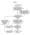
- FIG. 3 a flowchart illustrating an oil injection process for calculating the quantity of oil to be injected into the fuel system of the internal combustion engine and controlling the timing of the injection of such in accordance with the present invention is shown.
- the process begins at block 300 when an internal combustion engine containing an oil replacement system in accordance with the present invention is started.
- the oil replacement controller 18 Upon starting of the internal combustion engine, the oil replacement controller 18 will be initialized and the control program contained therein executed, beginning in block 302.
- the oil replacement controller 18 will reset an interval timer variable, an interval mileage variable, and an interval fuel consumption value which are preferably stored within the central processing unit of the controller 18.
- the interval timer and interval mileage variables are used to specify an interval period which limits the iterations of steps used to determine the quantity of oil to be injected into the fuel system. Once the interval period is reached, the injection process will then proceed to determine a base quantity of oil to be injected into the engine's fuel system during the specified interval period based on the fuel consumption value.
- the process next transfers control to decisional block 304, where it is determined if the interval selection variable (i.e. either the interval timer variable or interval mileage variable depending on the specific engine application) has reached a preset interval. If not, control passes to block 306 where the interval timer variable and/or the interval mileage variable are updated and recorded within the controller 18 along with the interval fuel consumption value. Control then again returns to block 304, thus forming an interval loop. The interval timer variable, interval mileage variable and interval fuel consumption value are updated based on the change in time, mileage and fuel consumption since the last iteration of the interval loop, thus resulting in a record of the cumulative amount of time and mileage in the current interval.
- the interval selection variable i.e. either the interval timer variable or interval mileage variable depending on the specific engine application
- cumulative totals for these variables are stored as well as a running history for each iteration of the interval loop. Also, during each pass through the interval loop, the current fuel consumption rate or fuel consumption quantity, as provided by ECM 19, is recorded.
- the interval loop acts to limit the iterations of steps used to determine the quantity of oil to be injected into the fuel system of the internal combustion engine. That is, due to the relatively small rate of injection of oil to the fuel system, it is only necessary to calculate the oil injection quantity on a periodic basis, approximately every minute.
- the interval loop is structured so that the preset interval will be reached by the internal selection variable approximately every minute.
- the interval loop functions to determine and record the fuel consumption rate or fuel consumption amount for the current interval.
- a fuel consumption value is determined.
- the fuel consumption value is preferably the instantaneous fuel consumption rate provided directly by ECM 19, as discussed hereinabove.
- the instantaneous fuel consumption rate may be calculated, and then recorded, using engine speed and fuel rail pressure information received from the engine speed and pressure sensors discussed hereinabove.
- the instantaneous fuel consumption values are averaged to obtain an average fuel consumption rate, or fuel consumption quantity, as applicable, for the interval.
- a fuel consumption value corresponding to the amount of fuel burned may be provided instead of a fuel consumption rate value.
- an average fuel consumption rate is continuously calculated as each instantaneous fuel consumption rate is determined during the current interval.
- this current amount of oil is added to the total amount of oil to be injected from previous interval periods, if any, to result in a cumulated oil quantity to be injected. That is, the amount of oil to be injected for a certain number of interval periods is summed to form a cumulated oil quantity to be injected. As noted below, once this cumulated oil quantity exceeds a predetermined threshold, an injection event is initiated and the cumulated oil quantity reset.
- the cumulated oil quantity could be reduced only by the unit injection quantity (instead of being reset to zero) to provide for greater accuracy in the oil replacement system of the present invention, if necessary.
- the most preferred embodiment of the present invention uses a fuel consumption value as an indication of the engine operating severity since fuel consumption closely correlates to the operating severity of the engine and thus the deterioration of the lube oil.
- other engine operating parameters which correlate to the severity of engine operation may be used, such as engine exhaust air temperature.
- the engine operating severity value i.e. preferably an average or total, depending on the parameter, as opposed to an instantaneous value, would be calculated for a current interval of engine operation and used in the process of the present invention in a similar manner as the fuel consumption value.
- the correlation of the engine operating severity value to the severity of engine operation and the determination of the oil to be injected would be dependent on the particular severity value used as discussed hereinbelow.
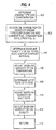
- an oil change period of 25,000 miles (about 40225 km) is determined from the appropriate data table in block 402. If the engine has an oil sump capacity of 11 gallons (about 41.64 l), then the baseline quantity of oil to be injected is equal to 11 gallons (about 41.64 l) divided by 25,000 miles (about 40225 km), or approximately 0.06 ounces-per-mile (about 1.057 g/km). If, however, the same engine is operating at a fuel consumption value of 5 miles-per-gallon, the oil change period is determined in block 402 to be 12,000 miles (about 19308 km). Thus, the baseline quantity of oil to be injected is equal to 11 gallons divided by 12,000 miles (about 19308 km), or approximately 0.12 ounces-per-mile (about 2.114 g/km).
- the baseline quantity is adjusted by the oil temperature.
- the baseline quantity will be increased by as much as 50 %, generally in proportional relationship to the amount by which the oil temperature exceeds 255 °F (about 123.9 °C).
- the system next adjusts the baseline quantity based on the soot producing characteristics of the internal combustion engine operating at the specific fuel consumption value.
- the system first reads a soot data table to determine the soot rate of the engine for the current interval fuel consumption value and fuel quality. This value is used in block 410 to adjust the baseline quantity of oil to be injected such that a higher soot rate results in an increase in the baseline quantity of oil to be injected, while a lower soot rate results in a decrease in the baseline quantity of oil to be injected.
- the baseline quantity of oil to be injected can optionally be further adjusted in accordance with a number of factors, if desired.
- the baseline quantity can be adjusted based on the quality of the oil used in the internal combustion engine.
- the amount of oil to be disposed through injection into the fuel could be reduced.
- the amount to be injected could be increased accordingly.
- adjustments could be made to the baseline quantity based on the sulfur content of the fuel.
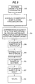
- FIG. 5 A second embodiment of the process for calculating the quantity of oil to be injected for a particular interval is illustrated in FIG. 5.
- the quantity oil to be injected is based on a desired oil concentration value.
- the oil concentration value which may vary depending on the engine type and configuration.
- the process begins in block 500 where the system determines the internal combustion engine type and configuration based on initial set-up information provided to the oil replacement controller 18.
- initial set-up information for a plurality of internal combustion engine types and configurations could be stored, for example, in memory 216 discussed above in connection with FIG. 2 and could be selected based on a DIP switch or jumper connection on the oil replacement controller 18, such as through the use of engine type selection switches 232.
- the internal combustion engine type and configuration information could itself be provided by an external DIP switch, jumper block, or the like.
- the configuration information could include, for example, the specific fuel system in use on the internal combustion engine and any other suitable information impacting the fuel consumption of the engine.
- Control then transfers to block 502, where the specific engine type and configuration of the internal combustion engine is used as an index to a data table to access an oil concentration value.
- Control then passes to block 504 where the oil concentration value is multiplied by the current fuel consumption value or rate of the internal combustion engine to determine a baseline quantity of oil to be injected into the fuel system of the internal combustion engine. For example, for a given engine type and configuration, an oil concentration value of .03 % may be accessed in block 502 and multiplied by the current fuel consumption value of, for example, 7 miles-per-gallon (about 2.98 km/l) to obtain the current baseline quantity of oil to be injected.
- Control next transfers sequentially to blocks 506, 508, 510 and 512 where the baseline quantity is adjusted based on the oil temperature, the soot producing rate of the fuel and the quality of the lube oil, as discussed with respect to the preferred embodiment of FIG. 4.
- control Upon completion of the process illustrated in FIG. 6, control returns at block 514 to block 312 shown in FIG. 3.
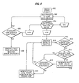
- FIG. 6 a second important aspect of the present invention in which a diagnostic process is performed to monitor the oil sump level, to transfer oil from auxiliary oil tank 40 to primary oil sump 24 if necessary, and to alert an operator to a fault condition in the oil replacement system of the present invention will now be discussed in detail.
- the most preferred embodiment of the diagnostic process begins at block 600 when an internal combustion engine containing an oil replacement system in accordance with the present invention is started.
- the controller 18 containing the diagnostic process will be initialized and the control program contained therein executed, beginning in block 602.
- Control then transfers to decisional block 612, where the process determines if the primary oil sump level is medium. If the oil level is medium, then the oil addition performed in block 610 was sufficient to replenish primary oil sump 24 and control transfers to block 606 to verify that the solenoid of auxiliary oil control device 44 is functioning properly. If the oil level is not medium, then the oil addition performed in block 610 was insufficient to replenish the primary oil sump, and control transfers to decisional block 614.
- the diagnostic process determines if the auxiliary oil tank level sensor is low. That is, the diagnostic process reads an auxiliary oil tank level sensor and processes the resulting level information to determine if sufficient oil remains in auxiliary oil tank 40. If auxiliary tank 40 does not contain a sufficient amount of oil (i.e. the level is low), then control transfers to block 616 where a fault code is generated alerting the operator of the need to add oil to auxiliary oil tank 40. Control then returns to decisional block 618 discussed hereinbelow. If it is determined in decisional block 614 that the auxiliary oil tank level is not low, the control transfers directly to decisional block 618.
- decisional block 618 the diagnostic process determines if the solenoid of auxiliary flow control device 44 is functional. That is, the diagnostic process makes a similar determination as that made in decisional block 606. In block 618, however, if it is determined that the solenoid is functional, then control returns to block 610, where additional oil is transferred from auxiliary oil tank 40 to primary oil sump 24. This process continues until the primary oil sump level has been adequately replenished.
- the diagnostic process of FIG. 6 could be simplified such that as a result of the low level signal, oil is transferred from auxiliary tank 40 to the primary oil sump 24.
- the diagnostic process would merely generate an appropriate dashboard indicator to the vehicle operator indicating the need for oil addition, etc.
- the diagnostic process of the present invention will also record the amount of oil being transferred from auxiliary tank 40 to the primary oil sump 24 and compare this value at regular intervals with the fuel consumption value and/or the amount of oil injected into the fuel system of the engine. By making this comparison, the diagnostic process can determine if the replacement rate is higher or lower than the injection rate to detect an oil pan leak or other malfunctioning.
- the present lube oil replacement system results in several important advantages.
- the present system maintains the quality of the lube oil in sump 24 at an optimum level throughout engine operation regardless of engine operating conditions.
- the present system is capable of automatically and continuously determining the current level of distress or wear imparted upon the oil based on varying engine operating conditions and continuously adjusting the replacement rate to obtain an optimum level of engine lubrication throughout engine operation. This is accomplished by variably controlling the amount of oil drained from the sump and injected into the fuel system based on the severity of engine operation as indicated by, for example, fuel consumption of the engine, and other factors such as engine temperature and oil soot contamination levels.
- the present system will increase the frequency of used lube oil injections into the fuel system and accordingly increase the frequency of new lube oil injections from auxiliary tank 40 into sump 24.
- the present system will decrease the frequency of used lube oil injections into the fuel system and accordingly decrease the frequency of new lube oil injections from auxiliary tank 40 into sump 24.
- the present system variable controls the frequency of lube oil replacement by controlling the frequency of operation of injection control device 16 and auxiliary lube oil flow control device 44.
- a conventional "preset" continuous lube oil replacement system injects predetermined quantities of lube oil at preset time intervals throughout engine operation.
- the injection quantity or the frequency of injections is adjustably set to cause replacement of the entire sump according to the regular recommended oil change period for the particular engine regardless of engine operating conditions. If the engine is operated at greater than normal capacity, the conventional system will continue to inject the same quantity of oil over time. As a result, over time, the lube oil will periodically reach levels of high degradation causing increased engine wear.
- Each engine is an M11 engine, manufactured by the assignee of the present invention, Cummins Engine Co., Inc., having a 100 gallon (about 378.54 l) fuel tank and an 11 gallon (about 41.64 l) oil sump.
- the engine pumps 40 gallons per hour (about 151,42 l/h) of fuel through the fuel system continuously. When operating at full power, this engine will burn approximately 16 gallons per hour (about 60.57 l/h) with the remaining returning to the fuel tank. When operating at nearly no load, the engine will burn 4 gallons of fuel per hour (about 15.14 l/h).
- the fuel is a low sulfur fuel with 0.045 % sulfur and the lubricant contains 0,45 % sulfur.
- Engine A includes a conventional "preset" injection system with a preset injection rate of lube oil into the fuel system based on no load conditions.
- Engine B includes the present continuous lube oil replacement system.
- the engines are operated at full power, i.e. under full load conditions, for the recommended oil change period of 12,000 miles (about 19308 km) for full power operation.
- the conventional system in engine A fails to respond to the need for increased oil replacement under the heavier operating conditions of the engine by only replacing 2.7 gallons (about 10.21) under full power conditions.
- the lube oil in the engine's lube oil system becomes over-used causing increased engine wear.
- Another advantage of the present invention is the ability to maintain the lube oil concentration in the fuel below a level necessary to maintain the sulfur content of the fuel below the acceptable limit of .05%. It has been found that, for the typical oil, the lube oil concentration in the fuel should be less than 1% at all times during engine operation and preferably approximately .5% to maintain the sulfur content of a typical low sulfur fuel below .05%. Conventional systems are less capable of maintaining the sulfur content below .05% since at certain engine operating conditions more oil will be injected into the fuel system than is necessary. The likelihood of conventional systems resulting in unacceptably high sulfur levels in the fuel is especially high when the engine is operating at a capacity less than the capacity corresponding to the preset injection rate.
- the conventional "preset" system may inject an excessive amount of lube oil into the fuel causing the cumulative sulfur content of the oil and fuel to exceed the acceptable limit of .05%. Excessive oil concentrations may also adversely affect the engine emissions resulting in emissions noncompliance.
- the present system maintains the sulfur concentration within acceptable limits by varying the injection rate based on engine conditions and is also more likely to maintain emissions within regulatory limits throughout operation of the engine. As shown in Table I, although the present system injects more oil to provide optimal engine protection at higher engine loads, the fuel sulfur content and oil concentration are maintained within acceptable limits.
- the present continuous lube oil replacement system may be used in any internal combustion engine having a supply of lubricating fluid for lubricating the engine's components.
- the present system is particularly useful in a compression ignition engine of any vehicle, such as a truck or boat, or industrial equipment, such as construction or earth moving machines.
Landscapes
- Engineering & Computer Science (AREA)
- Mechanical Engineering (AREA)
- General Engineering & Computer Science (AREA)
- Lubrication Details And Ventilation Of Internal Combustion Engines (AREA)
- Lubrication Of Internal Combustion Engines (AREA)
Claims (16)
- Elektronisch gesteuertes System (10) für wenigstens im wesentlichen kontinuierliches Wechseln von Schmieröl in einem Motor, wobei das Wechselsystem (10) aufweist:wobei ein Zusatzschmierölversorgungsmittel (22) zum Zuleiten von frischem Schmieröl zu dem Hauptschmierölversorgungsmittel (12) vorgesehen ist oder ein Bedarf einer Ölzugabe angezeigt wird,ein Kraftstoffversorgungssystem (20) zum Zuleiten von Kraftstoff zu dem Motor, wobei das Kraftstoffversorgungssystem (20) einen Kraftstofftank (30) und einen Kraftstoffversorgungskreis (32) aufweist, der den Kraftstofftank (30) mit dem Motor verbindet,ein Hauptschmierölversorgungsmittel (12), das ein Kurbelgehäuse oder einen Sumpf (24) umfasst, das bzw. der einen angesammelten Vorrat an Schmieröl enthält, und weiter einen Schmierölversorgungskreis (26) zur Abgabe eines Vorrats an Schmieröl an den Motor umfasst,einen Schmieröleinspritzkreis (14), der an den Schmierölversorgungskreis (26) und das Kraftstoffversorgungssystem (20) angeschlossen ist, so dass Einspritzmengen von gebrauchtem Schmieröl, die dem Kurbelgehäuse oder dem Sumpf (24) entnommen werden, diskontinuierlich von dem Schmierölversorgungskreis (26) zu dem Kraftstoffversorgungssystem (20) strömen, um mit dem Kraftstoff vermischt zu werden,ein Schmieröleinspritzsteuermittel (16), das entlang dem Schmieröleinspritzkreis (14) angeordnet ist, um diskontinuierlich bzw. intermittierend die Einspritzmengen von gebrauchtem Schmieröl in das Kraftstoffversorgungssystem (20) einzuspritzen,ein Motorbetriebsbedingungserfassungsmittel (19) zum Erfassen wenigstens einer Motorbetriebsbedingung und zum Erzeugen eines Motorbetriebsbedingungssignals, das die wenigstens eine Motorbetriebsbedingung anzeigt, undein Verarbeitungsmittel (18) zum Empfangen des Motorbetriebsbedingungssignals und zum Erzeugen eines Einspritzstromsteuersignals, wobei das Einspritzstromsteuersignal den Betrieb des Schmieröleinspritzsteuermittels (16) steuert, um eine Frequenz der diskontinuierlichen bzw. intermittierenden Einspritzung der Einspritzmengen von gebrauchtem Schmieröl zu ändern,
wobei das Verarbeitungsmittel (18) zur Berechnung eines Motorbetriebsheftigkeitswertes, der die Heftigkeit des Betriebs abhängig von dem Motorbetriebsbedingungssignal anzeigt, und zur Erzeugung des Einspritzstromsteuersignals abhängig von dem Motorbetriebsheftigkeitswert ausgebildet ist, und wobei gebrauchtes Schmieröl in den Kraftstoffversorgungskreis (32) zu dem Motor eingespritzt wird. - System nach Anspruch 1, dadurch gekennzeichnet, dass das Schmieröleinspritzsteuermittel (16) eine Einspritzpumpe enthält, die diskontinuierlich betrieben wird, um eine gesteuerte, vorbestimmte Menge an gebrauchtem Schmieröl in das Kraftstoffversorgungssystem (20) zu pumpen.
- System nach Anspruch 1 oder 2, dadurch gekennzeichnet, dass das Zusatzschmierölversorgungsmittel (22) einen Zusatzschmierölversorgungskreis (42) umfasst, um einen Zusatzschmierölversorgungsstrom zu dem Hauptschmierölversorgungsmittel (12) bereitzustellen, und einen Zusatzschmieröltank (40), der einen Vorrat an Zusatzschmieröl enthält, wobei das System (10) weiter ein Zusatzschmierölstromsteuermittel (44) umfasst, das entlang dem Zusatzschmierölversorgungskreis (42) angeordnet ist, um den Zusatzversorgungsstrom von Schmieröl zu dem Hauptschmierölversorgungsmittel (12) zu steuern, wobei vorzugsweise das Verarbeitungsmittel (18) ein Zusatzstromsteuersignal erzeugt, um den Betrieb des Zusatzschmierölstromsteuermittels (44) zu steuern.
- System nach Anspruch 3, dadurch gekennzeichnet, dass der Zusatzschmierölversorgungskreis (42) den Zusatzschmieröltank (40) mit dem Sumpf (24) verbindet, um den Zusatzversorgungsstrom zu dem Sumpf (24) abzugeben, vorzugsweise weiter umfassend einen Schmierölsumpfpegelsensor (212) zum Erfassen eines Sumpfschmierölpegels in dem Sumpf (24) und zum Erzeugen eines entsprechenden Pegelsignals, wobei das Verarbeitungsmittel (18) das Pegelsignal empfängt und das Stromsteuersignal abhängig von dem Pegelsignal erzeugt, um den Betrieb des Zusatzschmierölstromsteuermittels (44) zu steuern, um den Sumpfschmierölpegel bei einem annehmbaren Pegel zu halten, und wobei vorzugsweise das Zusatzschmierölstromsteuermittel (44) eine Einspritzpumpe umfasst, die diskontinuierlich betrieben wird, um eine gesteuerte, vorbestimmte Menge an Zusatzschmieröl in den Sumpf (24) zu pumpen.
- System nach einem der vorhergehenden Ansprüche, dadurch gekennzeichnet, dass das System (10) weiter ein elektronisches Steuermodul (19) zum Steuern des Motorbetriebs umfasst, wobei das elektronische Steuermodul (19) das Motorbedingungssignal dem Verarbeitungsmittel bereitstellt, und wobei vorzugsweise der Motorbetriebsheftigkeitswert ein Kraftstoffverbrauchswert ist, der einem Kraftstoffverbrauch des Motors während eines Betriebsintervalls entspricht.
- System nach einem der vorhergehenden Ansprüche, dadurch gekennzeichnet, dass das System (10) eine elektronische Steuerung (18) umfasst, wobei die Steuerung (18) umfasst
Eingangsmittel zum Empfangen des Motorbedingungssignals,
Ausgangsmittel zum Bereitstellen eines Ausgangssignals von der Steuerung zu einer Stromsteuervorrichtung zur Steuerung eines Schmierölstroms, und
das Verarbeitungsmittel (18), das mit dem Eingangsmittel und dem Ausgangsmittel zum Empfangen des Motorbedingungssignals verbunden ist, um ein Ausgangssignal auf der Basis der Menge an Schmieröl zu erzeugen, die einzuspritzen ist, und zum Leiten des Ausgangssignals zu dem Ausgangsmittel. - System nach Anspruch 6, dadurch gekennzeichnet, dass der Motorbetriebsheftigkeitswert ein Kraftstoffverbrauchswert ist, der einem Kraftstoffverbrauch des Motors während eines Betriebsintervalls entspricht, und/oder das Eingangsmittel ein Temperatursignal empfängt, das die Motorschmieröltemperatur anzeigt, und das Verarbeitungsmittel die Menge an einzuspritzendem Schmieröl auf der Basis des Temperatursignals einstellt, und/oder dass die Steuerung (18) weiter ein Rußinformationsspeichermittel zum Speichern einer Rußinformation umfasst, wobei das Verarbeitungsmittel (18) auf das Rußinformationsspeichermittel zugreift, um einen Rußwert auszulesen, und die Menge an einzuspritzendem Schmieröl auf der Basis des Rußwertes einstellt, und/oder das Verarbeitungsmittel (18) die Menge an einzuspritzendem Öl auf der Basis einer Qualitätseigenschaft des Schmieröls einstellt.
- System nach Anspruch 6 oder 7, dadurch gekennzeichnet, dass die Steuerung (18) weiter ein Motorkonfigurationsspeichermittel umfasst, das an das Verarbeitungsmittel (18) angeschlossen ist, zum Speichern der Motorkonfigurationsinformationen für mehrere Motoren, und wobei vorzugsweise das Verarbeitungsmittel (18) den Kraftstoffverbrauchswert verarbeitet, indem es auf das Motorkonfigurationsspeichermittel zugreift und einen Ölwechselwert ausliest, welcher der Menge an Schmieröl entspricht, die in das Kraftstoffversorgungssystem (20) auf der Basis des Kraftstoffverbrauchswertes einzuspritzen ist.
- Verfahren zum Steuern eins Schmierölwechsels in einem Innenverbrennungsmotor mit einem Kraftstoffversorgungssystem (20), das Kraftstoff an den Motor abgibt, und einem Schmierölversorgungssystem (12), wobei das Verfahren folgende Schritte aufweist:wobei ein Motorbetriebsheftigkeitswert, der die Heftigkeit des Betriebs wiedergibt, auf der Basis des ersten Signals berechnet wird,Empfangen eines ersten Signals, das eine Betriebsbedingung des Motors anzeigt,Bestimmen einer Menge an gebrauchtem Schmieröl, die einem Kurbelgehäuse oder Sumpf (24) des Schmierölversorgungssystems (12) entnommen wird, um in das Kraftstoffversorgungssystem (20) eingespritzt zu werden, das einen Kraftstofftank (30) und einen Kraftstoffversorgungskreis (32) aufweist, der den Kraftstofftank (30) mit dem Motor verbindet, auf der Basis von wenigstens dem ersten Signal,Erzeugen eines Ausgangssignals auf der Basis der Menge an gebrauchtem Schmieröl,Leiten des Ausgangssignals zu einer Stromsteuervorrichtung zum Steuern eines Stroms gebrauchten Schmieröls von dem Schmierölversorgungssystem (12) in das Kraftstoffversorgungssystem (20) des Motors, undZuführen von frischem Schmieröl zu dem Schmierölversorgungssystem (12) oder Anzeigen der Notwendigkeit einer Ölzugabe,
der Motorbetriebsheftigkeitswert verarbeitet wird, um die Menge an gebrauchtem Schmieröl zu bestimmen, und
gebrauchtes Schmieröl in den Kraftstoffversorgungskreis (32) zu dem Motor eingespritzt wird. - Verfahren nach Anspruch 9, dadurch gekennzeichnet, dass das Verfahren den Schritt des Zugreifens auf Motorkonfigurationsinformationen für wenigstens einen Motor in einem Motorkonfigurationsspeichermittel umfasst, um einen Schmierölwechselwert zu lesen, welcher der Menge an gebrauchtem Schmieröl entspricht, die in das Kraftstoffversorgungssystem (20) einzuspritzen ist, auf der Basis des Motorbetriebsheftigkeitswertes, und/oder dass der Motorbetriebsheftigkeitswert ein Kraftstoffverbrauchswert ist, der einem Kraftstoffverbrauch des Motors während eines Betriebsintervalls entspricht.
- Verfahren nach Anspruch 9 oder 10, dadurch gekennzeichnet, dass die Menge an gebrauchtem Schmieröl, die einzuspritzen ist, in periodischen Intervallen während des gesamten Motorbetriebs bestimmt wird, und wobei vorzugsweise diese periodischen Intervalle auf einer Zeitvariablen und/oder einer Meilenzahlvariablen beruhen.
- Verfahren nach einem der Ansprüche 9 bis 11, dadurch gekennzeichnet, dass die Stromsteuervorrichtung imstande ist, eine vorbestimmte Einheitseinspritzmenge bei Empfang des Ausgangssignals einzuspritzen, wobei vorzugsweise die Zeitsteuerung der Einspritzung der vorbestimmten Einheitseinspritzmenge während des Motorbetriebs von dem Motorbetriebsheftigkeitswert abhängig ist.
- Verfahren nach einem der Ansprüche 9 bis 12, dadurch gekennzeichnet, dass das Verfahren den Schritt des Summierens der Menge an gebrauchtem Schmieröl, die einzuspritzen ist, für mehrere periodische Intervalle umfasst, um eine kumulierte einzuspritzende Schmierölmenge zu definieren, und vorzugsweise des Weiteren den Schritt des Vergleichens der kumulierten einzuspritzenden Schmierölmenge mit der vorbestimmten Einheitseinspritzmenge umfasst, und wobei vorzugsweise das Ausgangssignal zu der Stromsteuervorrichtung geleitet wird, wenn die kumulierte einzuspritzende Schmierölmenge größer als die vorbestimmte Einheitseinspritzmenge ist.
- Verfahren nach einem der Ansprüche 9 bis 13, dadurch gekennzeichnet, dass das Verfahren die Schritte des Erfassens der Schmieröltemperatur, Erzeugens eines Temperatursignals, das die Schmieröltemperatur anzeigt, und Einstellens der einzuspritzenden gebrauchten Schmierölmenge auf der Basis des Temperatursignals umfasst und/oder des Weiteren die Schritte des Zugreifens auf Rußinformationen in einem Rußinformationsspeichermittel, um einen Rußwert auszulesen, und des Einstellens der einzuspritzenden gebrauchten Schmierölmenge auf der Basis des Rußwertes umfasst, und/oder des Weiteren den Schritt des Einstellens der einzuspritzenden gebrauchten Schmierölmenge auf der Basis einer Qualitätseigenschaft des Schmieröls umfasst.
- Verfahren nach einem der Ansprüche 9 bis 14, dadurch gekennzeichnet, dass das Verfahren die Schritte des Bestimmens eines Sumpfschmierölpegels und des Leitens eines ersten Steuersignals zu einer Zusatzstromsteuervorrichtung umfasst, um eine erste Menge an Zusatzschmieröl von einem Zusatzschmieröltank (40) in den Sumpf (24) einzuspritzen, wenn der Sumpfschmierölpegel unter einem annehmbaren Pegel liegt,
vorzugsweise weiter umfassend den Schritt des Vorbestimmens des Sumpfschmierölpegels nach dem Einspritzen der ersten Menge an Zusatzschmieröl, des Bestimmens eines Zusatzschmierölpegels in dem Zusatzschmieröltank (40), wenn der Sumpfschmierölpegel unannehmbar ist, und des Erzeugens eines Fehlersignals zur Alarmierung eines Betreibers, wenn der Zusatzschmieröltankpegel nieder ist,
vorzugsweise weiter umfassend die Schritte des Bestimmens, ob die Zusatzstromsteuervorrichtung (44) richtig funktioniert, nach der Bestimmung des Zusatzschmierölpegels in dem Zusatzschmieröltank (40) und/oder wenn der Sumpfschmierölpegel höher als ein annehmbarer Pegel ist, und des Erzeugens eines Fehlersignals zur Alarmierung eines Betreibers, wenn die Zusatzstromsteuervorrichtung (44) nicht richtig funktioniert. - Verfahren nach einem der Ansprüche 9 bis 15, dadurch gekennzeichnet, dass der Strom an gebrauchtem Schmieröl abhängig von den tatsächlichen Betriebsbedingungen des Motors gesteuert wird, insbesondere von der Kraftstoffverbrauchsrate, der Abgastemperatur und/oder der Motorlast.
Applications Claiming Priority (2)
| Application Number | Priority Date | Filing Date | Title |
|---|---|---|---|
| US08/608,305 US5749339A (en) | 1996-02-28 | 1996-02-28 | Electronically controlled continuous lubricating oil replacement system |
| US608305 | 1996-02-28 |
Publications (2)
| Publication Number | Publication Date |
|---|---|
| EP0793005A1 EP0793005A1 (de) | 1997-09-03 |
| EP0793005B1 true EP0793005B1 (de) | 2003-07-02 |
Family
ID=24435910
Family Applications (1)
| Application Number | Title | Priority Date | Filing Date |
|---|---|---|---|
| EP97102021A Expired - Lifetime EP0793005B1 (de) | 1996-02-28 | 1997-02-08 | Elektronische Steueranlage zum kontinuierlichen Ölwechseln |
Country Status (6)
| Country | Link |
|---|---|
| US (3) | US5749339A (de) |
| EP (1) | EP0793005B1 (de) |
| JP (1) | JPH09329011A (de) |
| CN (1) | CN1158450C (de) |
| BR (1) | BR9701126B1 (de) |
| DE (1) | DE69723131T2 (de) |
Families Citing this family (109)
| Publication number | Priority date | Publication date | Assignee | Title |
|---|---|---|---|---|
| US6213080B1 (en) | 1996-02-28 | 2001-04-10 | Cummins Engine Company, Inc. | Electronically controlled continuous lubricating oil replacement system |
| US5749339A (en) * | 1996-02-28 | 1998-05-12 | Cummins Engine Company, Inc. | Electronically controlled continuous lubricating oil replacement system |
| DE19633189C2 (de) * | 1996-08-17 | 1998-12-24 | Daimler Benz Ag | Verfahren zur Erkennung von Ölnachfüllmengen |
| DE19705946A1 (de) * | 1997-02-17 | 1998-08-20 | Audi Ag | Verfahren und Vorrichtung zur Bestimmung des verbleibenden Teils eines Ölwechselintervalls einer Brennkraftmaschine |
| US6024272A (en) * | 1997-06-09 | 2000-02-15 | Myers; John E. | Precision alignment device for torque converter hubs |
| DE19747853A1 (de) * | 1997-10-30 | 1999-05-06 | Fuchs Petrolub Ag | Verfahren und Vorrichtung zur Schmierung und gleichzeitigen Kraftstoffversorgung eines Verbrennungsmotors |
| US5964318A (en) * | 1998-01-12 | 1999-10-12 | The Lubrizol Corporation | System for maintaining the quality and level of lubricant in an engine |
| US6023961A (en) | 1998-04-02 | 2000-02-15 | Reliance Electric Industrial Company | Micro-viscosity sensor and lubrication analysis system employing the same |
| US6079380A (en) * | 1998-10-02 | 2000-06-27 | Cummins Engine Company, Inc. | Electronically controlled lubricating oil and fuel blending system |
| US6273031B1 (en) | 1998-12-11 | 2001-08-14 | Nelson Industries, Inc. | Clean lubricant circulation system |
| US6208245B1 (en) * | 1999-08-02 | 2001-03-27 | Curtis Instruments, Inc. | Engine oil change indicator system |
| JP2001073737A (ja) * | 1999-09-05 | 2001-03-21 | Honda Motor Co Ltd | 内燃機関用オイルタンク |
| US6283082B1 (en) * | 1999-11-17 | 2001-09-04 | General Electric Company | Method and apparatus to extend the operating interval between oil changes for an internal combustion engine |
| US6457564B1 (en) | 1999-12-07 | 2002-10-01 | The Lubrizol Corporation | Combination lubrication system for an internal combustion engine and associated gear devices |
| US6397811B1 (en) | 2000-03-09 | 2002-06-04 | Cummins Inc. | Electronically controlled lubricating oil removal system |
| US6269788B1 (en) * | 2000-03-13 | 2001-08-07 | Robert L. Kachelek | Programmable computer controlled electric oil pump drive for engines |
| US6577959B1 (en) | 2000-03-17 | 2003-06-10 | Power Plus Corporation | Fluid level measuring system for machines |
| US6295971B1 (en) | 2000-05-25 | 2001-10-02 | Cummins Engine Company, Inc. | Lubricating oil and fuel blending system |
| US6485632B1 (en) * | 2000-08-04 | 2002-11-26 | Michael S. Ward | Apparatus and method for reclaiming waste oil for use as fuel for a diesel engine |
| US6588393B2 (en) * | 2000-09-19 | 2003-07-08 | The Lubrizol Corporation | Low-sulfur consumable lubricating oil composition and a method of operating an internal combustion engine using the same |
| US6463796B1 (en) * | 2000-10-12 | 2002-10-15 | The Lubrizol Corporation | Continuous on-board diagnostic lubricant monitoring system and method |
| US6463967B1 (en) | 2000-11-17 | 2002-10-15 | The Lubrizol Corporation | System for diagnosing, maintaining and reporting the performance and safety condition of apparatus during refueling |
| US6568436B1 (en) | 2000-12-04 | 2003-05-27 | The Lubrizol Corporation | System for periodic fluid maintenance of apparatus |
| US6390034B1 (en) * | 2000-12-07 | 2002-05-21 | Wacker Corporation | Reciprocating impact tool having two-cycle engine oil supply system |
| US6701897B2 (en) * | 2001-02-16 | 2004-03-09 | Optimum Power Technology | Engine fuel delivery management system |
| US7756717B2 (en) * | 2002-02-05 | 2010-07-13 | General Electric Company | Lubricant management method for a vehicle |
| US7490586B1 (en) * | 2002-07-12 | 2009-02-17 | Weller Richard G | Automatic engine oil changer/recycler system |
| US6914524B2 (en) * | 2003-02-27 | 2005-07-05 | Delphi Technologies, Inc. | Apparatus and method for detecting ignition and engine conditions |
| US7055486B2 (en) * | 2003-03-28 | 2006-06-06 | Caterpillar Inc. | Fluid delivery control system |
| CA2471914A1 (en) * | 2003-07-29 | 2005-01-29 | Doug Novlan | Engine lubricant management system |
| US7143867B2 (en) * | 2003-11-24 | 2006-12-05 | The United States Of America As Represented By The Secretary Of The Army | Electronic oil level detection and replacement system |
| DE102004033414A1 (de) * | 2004-07-10 | 2006-02-02 | Robert Bosch Gmbh | Verfahren zum Betreiben einer Brennkraftmaschine und Vorrichtung zur Durchführung des Verfahrens |
| US7506724B2 (en) * | 2004-07-23 | 2009-03-24 | Honeywell International Inc. | Active gas turbine lubrication system flow control |
| JP4086029B2 (ja) * | 2004-10-05 | 2008-05-14 | いすゞ自動車株式会社 | エンジンの制御装置及び制御方法 |
| US7686136B2 (en) * | 2004-11-08 | 2010-03-30 | Larry Douglas Evans | Automated oil-change system and method |
| JP2006158123A (ja) * | 2004-11-30 | 2006-06-15 | Toyota Motor Corp | 交流電圧出力装置およびそれを備えた車両 |
| WO2006110337A1 (en) * | 2005-04-07 | 2006-10-19 | Howard Gary L | Fluid transfer device |
| US20080179139A1 (en) * | 2007-01-30 | 2008-07-31 | Deere & Company | Oil change apparatus |
| US20080302606A1 (en) * | 2007-06-08 | 2008-12-11 | Glacier Bay, Inc. | Oil replacement system |
| US20090032337A1 (en) * | 2007-08-02 | 2009-02-05 | David John Scott | Lubricant grease supplying system and method of supplying lubricant grease using the system |
| US20090139484A1 (en) * | 2007-11-30 | 2009-06-04 | Caterpillar Inc. | Automatically adjustable oil renewal system |
| US8746410B1 (en) * | 2008-03-14 | 2014-06-10 | Raymond P. Lekowicz | Outdrive gear oil monitor |
| CA2779603C (en) * | 2009-11-16 | 2015-05-12 | Bell Helicopter Textron Inc. | Emergency subsystem for a fluid system |
| US20110123352A1 (en) * | 2009-11-22 | 2011-05-26 | Lai Ming Der | Electric pump with time setting and enhanced oil-pipe transfer capability |
| KR20140002730A (ko) * | 2011-02-09 | 2014-01-08 | 알리손 트랜스미션, 인크. | 스캐빈지 펌프 오일 레벨 제어 시스템 및 방법 |
| CA2827626C (en) | 2011-02-17 | 2018-05-15 | Allison Transmission, Inc. | Modulation control system and method for a hybrid transmission |
| WO2012125337A2 (en) | 2011-03-11 | 2012-09-20 | Allison Transmission, Inc. | Clogged filter detection system and method |
| AU2012273001B2 (en) | 2011-06-22 | 2015-04-23 | Allison Transmission, Inc. | Low level oil detection system and method |
| NL2007335C2 (en) * | 2011-09-02 | 2013-03-05 | Groeneveld Transp Efficiency B V | Oil management system for an internal combustion engine, and a method for oil management of such an engine. |
| EP2573338B1 (de) | 2011-09-20 | 2017-07-19 | Safran Aero Boosters SA | Überfüllungskontrolle eines Schmiersystems für einen Flugzeugmotor |
| CN102434245A (zh) * | 2011-11-23 | 2012-05-02 | 上海科泰电源股份有限公司 | 一种柴油发电机组的润滑油系统 |
| US8887509B2 (en) * | 2012-03-02 | 2014-11-18 | Hamilton Sundstrand Corporation | Liquid level monitoring and reporting system |
| US8868283B2 (en) * | 2012-05-03 | 2014-10-21 | GM Global Technology Operations LLC | Oil life monitoring system with fuel quality factor |
| CN103822686B (zh) * | 2012-11-16 | 2016-12-21 | 重庆长安汽车股份有限公司 | 发动机润滑系统机油油量的实时测试装置及方法 |
| JP2016501332A (ja) | 2012-11-19 | 2016-01-18 | カストロール リミテッド | 容器、方法および制御システム |
| JP5902600B2 (ja) * | 2012-11-26 | 2016-04-13 | 愛三工業株式会社 | オイル貯留量判定装置 |
| CN103061902B (zh) * | 2012-12-31 | 2016-06-29 | 林秋雄 | 一种增益动力的内燃机运行控制方法 |
| US9334769B2 (en) | 2013-01-25 | 2016-05-10 | Cummins Power Generation Ip, Inc. | Apparatuses, systems, and methods for crankcase oil sump overfill protection |
| US9605569B1 (en) * | 2013-03-15 | 2017-03-28 | Raymond Lekowicz | Closed-loop oil-transfer system for a vehicle |
| CN104343491B (zh) * | 2013-07-24 | 2017-03-08 | 中国国际航空股份有限公司 | 一种发动机滑油添加探测系统及方法 |
| US20150053505A1 (en) * | 2013-08-05 | 2015-02-26 | Briggs & Stratton Corporation | Engine oil recirculation system for extended maintenance interval |
| US9458966B2 (en) * | 2013-08-07 | 2016-10-04 | Graco Minnesota Inc. | Lubrication system automatic shutoff |
| CN103807590B (zh) * | 2013-11-13 | 2016-04-06 | 浙江吉利控股集团有限公司 | 可自动补油的润滑装置 |
| GB201409082D0 (en) | 2014-05-21 | 2014-07-02 | Castrol Ltd | Fluid container |
| CN105443193B (zh) * | 2014-08-11 | 2019-04-16 | 刘新羽 | 一种汽车发动机润滑油保证装置及其控制方法 |
| US9714931B2 (en) | 2014-09-03 | 2017-07-25 | General Electric Company | System and method for estimating engine oil health |
| RU2018143233A (ru) * | 2016-05-13 | 2020-06-16 | Кастрол Лимитед | Устройство и способ |
| CN107387197B (zh) * | 2016-05-16 | 2019-07-19 | 北汽福田汽车股份有限公司 | 一种发动机润滑系统、发动机及车辆 |
| US20180087420A1 (en) * | 2016-09-23 | 2018-03-29 | Bell Helicopter Textron Inc. | Oil-level sensor for a gearbox |
| CN106337708B (zh) * | 2016-09-26 | 2019-03-22 | 江苏理工学院 | 灵活型发动机机油切换分离方法 |
| CN106246279B (zh) * | 2016-09-26 | 2019-05-03 | 江苏理工学院 | 发动机机油切换方法 |
| CN106437932B (zh) * | 2016-09-26 | 2019-03-22 | 江苏理工学院 | 防泼型发动机机油切换方法 |
| CN106321185B (zh) * | 2016-09-26 | 2018-10-30 | 江苏理工学院 | 发动机机油切换分离装置 |
| CN106321186B (zh) * | 2016-09-26 | 2018-10-16 | 江苏理工学院 | 发动机机油切换装置 |
| CN106194324B (zh) * | 2016-09-26 | 2018-10-16 | 江苏理工学院 | 发动机机油切换分离方法 |
| CN106437933B (zh) * | 2016-09-26 | 2019-04-23 | 江苏理工学院 | 防泼型发动机机油切换装置 |
| US10289126B2 (en) | 2016-10-11 | 2019-05-14 | Fuel Automation Station, LLC | Mobile distribution station with guided wave radar fuel level sensors |
| US9790080B1 (en) | 2016-10-11 | 2017-10-17 | Fuel Automation Station, LLC | Mobile distribution station with fail-safes |
| US10087065B2 (en) | 2016-10-11 | 2018-10-02 | Fuel Automation Station, LLC | Mobile distribution station having sensor communication lines routed with hoses |
| US9815683B1 (en) | 2016-10-11 | 2017-11-14 | Fuel Automation Station, LLC | Method and system for mobile distribution station |
| US9586805B1 (en) | 2016-10-11 | 2017-03-07 | Fuel Automation Station, LLC | Mobile distribution station with aisle walkway |
| CN106567960B (zh) * | 2016-10-17 | 2019-07-05 | 潍柴动力股份有限公司 | 一种电磁阀的控制方法和系统 |
| US10473009B2 (en) * | 2017-01-18 | 2019-11-12 | Vavoline Licensing and Intellectual Property LLC | System and method for predicting remaining oil life in vehicles |
| US10633243B2 (en) | 2017-02-24 | 2020-04-28 | Fuel Automation Station, Llc. | Mobile distribution station |
| US10150662B1 (en) | 2017-10-27 | 2018-12-11 | Fuel Automation Station, Llc. | Mobile distribution station with additive injector |
| PL4242512T3 (pl) * | 2017-10-31 | 2026-02-23 | Maersk A/S | Urządzenie i sposób mieszania oleju na statku morskim |
| RU2679099C1 (ru) * | 2018-03-12 | 2019-02-05 | Общество с ограниченной ответственностью "Промышленные инновации" (ООО "Промышленные инновации") | Устройство контроля состояния масла |
| CN108443158A (zh) * | 2018-04-26 | 2018-08-24 | 贺吉军 | 空调系统和螺杆压缩机及其润滑油检测装置 |
| US10926996B2 (en) | 2018-05-04 | 2021-02-23 | Fuel Automation Station, Llc. | Mobile distribution station having adjustable feed network |
| CN108678834A (zh) * | 2018-05-11 | 2018-10-19 | 浙江吉利控股集团有限公司 | 一种发动机电控自动补机油系统及补机油方法 |
| CA3081789C (en) * | 2018-05-14 | 2022-09-13 | Whitmore Manufacturing, Llc | Apparatus and method for dispensing a lubricant to the rail and determining the amount of lubricant dispensed and remaining |
| RU184851U1 (ru) * | 2018-05-17 | 2018-11-12 | Федеральное государственное бюджетное образовательное учреждение высшего образования "Кубанский государственный технологический университет" (ФГБОУ ВО "КубГТУ") | Устройство контроля качества моторного масла |
| CN108918152B (zh) * | 2018-05-18 | 2020-10-23 | 中国航发湖南动力机械研究所 | 航空发动机试验装置 |
| CA3051985C (en) | 2018-08-24 | 2022-08-09 | Fuel Automation Station, LLC | Mobile distribution station having satellite dish |
| CN109027656B (zh) * | 2018-10-25 | 2020-10-23 | 义乌市研创工业设计有限公司 | 一种用于机油的车载存储设备及其工作方法 |
| CN109594237B (zh) * | 2018-12-05 | 2021-03-12 | 杰克缝纫机股份有限公司 | 一种缝纫机 |
| DE102019111030A1 (de) * | 2019-04-29 | 2020-10-29 | Man Energy Solutions Se | Verfahren und Steuergerät zum Betreiben einer Diesel-Brennkraftmaschine oder einer im Diesel-Betriebsmodus betriebenen Dual-Fuel-Brennkraftmaschine |
| DE102019111012A1 (de) * | 2019-04-29 | 2020-10-29 | Man Energy Solutions Se | Verfahren und Steuergerät zum Betreiben einer Otto-Brennkraftmaschine oder einer im Otto-Betriebsmodus betriebenen Dual-Fuel-Brennkraftmaschine |
| JP2022543054A (ja) * | 2019-08-01 | 2022-10-07 | カストロール リミテッド | サンプ液レベルの調整方法およびシステム |
| US11142449B2 (en) | 2020-01-02 | 2021-10-12 | Fuel Automation Station, LLC | Method and system for dispensing fuel using side-diverting fuel outlets |
| US11827421B2 (en) | 2020-01-17 | 2023-11-28 | Fuel Automation Station, LLC | Fuel cap assembly with cylindrical coupler |
| JP7600256B2 (ja) * | 2020-03-12 | 2024-12-16 | ジョンソン・コントロールズ・タイコ・アイピー・ホールディングス・エルエルピー | 暖房、換気、又は空調(hvac)システム内の障害を予測するためのコントローラ及び方法 |
| CA3153805A1 (en) * | 2020-05-18 | 2021-11-25 | Richard John Donahue | System and method for extending oil life in an engine |
| JP7359132B2 (ja) * | 2020-11-30 | 2023-10-11 | トヨタ自動車株式会社 | 制御装置、車両、プロブラム及び制御装置の動作方法 |
| CN112814761A (zh) * | 2021-01-06 | 2021-05-18 | 上海三一重机股份有限公司 | 机油监测方法、装置及机械设备 |
| CN112761753B (zh) * | 2021-01-14 | 2022-04-29 | 东风商用车有限公司 | 一种发动机的机油精确加注机构及其加注方法 |
| US11639771B2 (en) * | 2021-02-08 | 2023-05-02 | Saudi Arabian Oil Company | Integrated system and method for automatic rejuvenation of turbine oil for improving equipment reliability |
| CN114324828B (zh) * | 2021-12-31 | 2022-11-08 | 崇左南方水泥有限公司 | 一种回转窑托轮润滑检测系统 |
| KR102795866B1 (ko) * | 2022-10-17 | 2025-04-17 | 유수호 | 오일 자동 공급장치 |
Family Cites Families (25)
| Publication number | Priority date | Publication date | Assignee | Title |
|---|---|---|---|---|
| GB720222A (en) * | 1952-07-07 | 1954-12-15 | Cav Ltd | A lubrication and fuel oil system for internal combustion engines |
| GB867711A (en) * | 1956-09-29 | 1961-05-10 | Maschf Augsburg Nuernberg Ag | Means for creating a controlled consumption of lubricating oil in injection type internal combustion engines |
| US3447636A (en) * | 1967-07-24 | 1969-06-03 | Ralph J Bonfilio | Automatic oil exchanging system |
| GB1454184A (en) * | 1974-09-18 | 1976-10-27 | Assa Ab | Lubrication system |
| US4417561A (en) * | 1979-05-26 | 1983-11-29 | Nissan Motor Co., Ltd. | Method and apparatus for automatically changing and disposing of used engine oil |
| JPS5824602B2 (ja) * | 1979-09-26 | 1983-05-23 | 日産自動車株式会社 | 車両用エンジンの潤滑油劣化低減装置 |
| US4421078A (en) * | 1980-09-29 | 1983-12-20 | Hurner Erwin E | Oil changing system |
| US4495909A (en) * | 1980-12-22 | 1985-01-29 | Hurner Erwin E | Oil cleaning and recycling system |
| JPS6044490B2 (ja) * | 1981-07-29 | 1985-10-03 | 日産自動車株式会社 | エンジンオイル交換指示装置 |
| JPS6090910A (ja) * | 1983-10-24 | 1985-05-22 | Sanshin Ind Co Ltd | 2サイクル内燃機関の潤滑油供給装置 |
| JPS60178915A (ja) * | 1984-02-24 | 1985-09-12 | Honda Motor Co Ltd | 2サイクルエンジンの潤滑油供給制御装置 |
| JPS6299608A (ja) * | 1985-10-28 | 1987-05-09 | Honda Motor Co Ltd | 内燃エンジンの燃料混合供給装置 |
| US4674456A (en) * | 1985-12-13 | 1987-06-23 | Merritt Timothy K | Oil-changing system for an internal combustion engine |
| US5390762A (en) * | 1987-08-14 | 1995-02-21 | Power Plus Corporation | Automatic crankcase oil change and makeup system |
| US4869346A (en) * | 1987-08-14 | 1989-09-26 | Nelson Donald M | Automatic crankcase oil change and makeup system |
| US5390635A (en) * | 1992-03-16 | 1995-02-21 | Yamaha Hatsudoki Kabushiki Kaisha | Lubricating oil supplying system for engine |
| JPH06229219A (ja) * | 1993-02-03 | 1994-08-16 | Yamaha Motor Co Ltd | 2サイクルエンジンの潤滑装置 |
| US5431138A (en) * | 1994-02-25 | 1995-07-11 | Hurner; Erwin E. | Oil cleaning and recycling system |
| JP3271037B2 (ja) * | 1994-05-26 | 2002-04-02 | 日石三菱株式会社 | 内燃機関用潤滑油の補給方法及び装置 |
| JPH0814093A (ja) * | 1994-06-24 | 1996-01-16 | Sanshin Ind Co Ltd | 2サイクルエンジンの始動制御装置 |
| US5586538A (en) * | 1995-11-13 | 1996-12-24 | Caterpillar Inc. | Method of correcting engine maps based on engine temperature |
| US5749339A (en) * | 1996-02-28 | 1998-05-12 | Cummins Engine Company, Inc. | Electronically controlled continuous lubricating oil replacement system |
| US5970942A (en) * | 1996-02-28 | 1999-10-26 | Cummins Engine Company, Inc. | Electronically controlled continuous lubricating oil replacement system |
| US5941745A (en) * | 1996-09-06 | 1999-08-24 | Sanshin Kogyo Kabushiki Kaisha | Fuel and lubricant system for marine engine |
| US5964318A (en) * | 1998-01-12 | 1999-10-12 | The Lubrizol Corporation | System for maintaining the quality and level of lubricant in an engine |
-
1996
- 1996-02-28 US US08/608,305 patent/US5749339A/en not_active Expired - Lifetime
-
1997
- 1997-02-08 DE DE69723131T patent/DE69723131T2/de not_active Expired - Lifetime
- 1997-02-08 EP EP97102021A patent/EP0793005B1/de not_active Expired - Lifetime
- 1997-02-28 CN CNB971028397A patent/CN1158450C/zh not_active Expired - Fee Related
- 1997-02-28 JP JP9045356A patent/JPH09329011A/ja active Pending
- 1997-02-28 BR BRPI9701126-6A patent/BR9701126B1/pt not_active IP Right Cessation
-
1998
- 1998-01-14 US US09/007,048 patent/US5881688A/en not_active Expired - Lifetime
- 1998-12-23 US US09/219,716 patent/US6082322A/en not_active Expired - Lifetime
Also Published As
| Publication number | Publication date |
|---|---|
| JPH09329011A (ja) | 1997-12-22 |
| DE69723131D1 (de) | 2003-08-07 |
| CN1158450C (zh) | 2004-07-21 |
| CN1160135A (zh) | 1997-09-24 |
| DE69723131T2 (de) | 2004-05-27 |
| BR9701126A (pt) | 1998-10-27 |
| US6082322A (en) | 2000-07-04 |
| EP0793005A1 (de) | 1997-09-03 |
| BR9701126B1 (pt) | 2010-05-18 |
| US5749339A (en) | 1998-05-12 |
| US5881688A (en) | 1999-03-16 |
Similar Documents
| Publication | Publication Date | Title |
|---|---|---|
| EP0793005B1 (de) | Elektronische Steueranlage zum kontinuierlichen Ölwechseln | |
| US5970942A (en) | Electronically controlled continuous lubricating oil replacement system | |
| US6213080B1 (en) | Electronically controlled continuous lubricating oil replacement system | |
| US6079380A (en) | Electronically controlled lubricating oil and fuel blending system | |
| EP0928883B1 (de) | Vorrichtung zur Aufrechthaltung der Ölqualität und des Ölstandes in einer Brennkraftmaschine | |
| US20090139484A1 (en) | Automatically adjustable oil renewal system | |
| US4674456A (en) | Oil-changing system for an internal combustion engine | |
| KR100330275B1 (ko) | 연료누출검출기시스템 | |
| US6513367B2 (en) | Method of monitoring engine lubricant condition | |
| AU716805B2 (en) | Apparatus and method for burning spent lubricating oil in an internal combustion engine | |
| EP2722500B1 (de) | System und Verfahren zur Dosierung von Schmieröl in große Dieselmotorzylinder | |
| US4417561A (en) | Method and apparatus for automatically changing and disposing of used engine oil | |
| EP1847706A1 (de) | Kraftstoffzufuhrsystem für einen Dieselmotor | |
| EP0684368B1 (de) | Verfahren und Einrichtung zum Nachfüllen von Schmieröl in eine Brennkraftmaschine | |
| US20140172277A1 (en) | Engine diagnostic system and method | |
| WO1994011627A1 (en) | Process for the indication of abnormalities in vehicles driven by internal combustion engines | |
| EP2312413B1 (de) | Brennstofffilterungsüberwachungssystem | |
| US20080302606A1 (en) | Oil replacement system | |
| US11339737B1 (en) | Method and system for fuel filter monitoring | |
| EP0885350B1 (de) | Einspritzsystem für die ölerneuerung in verbrennungsmotoren | |
| JP2013044241A (ja) | 警告装置 | |
| JP4798114B2 (ja) | オイル潤滑装置 | |
| EP1356192B1 (de) | Vorrichtung zur steuerung eines schmierfluidpegels | |
| US6397811B1 (en) | Electronically controlled lubricating oil removal system | |
| US6295971B1 (en) | Lubricating oil and fuel blending system |
Legal Events
| Date | Code | Title | Description |
|---|---|---|---|
| PUAI | Public reference made under article 153(3) epc to a published international application that has entered the european phase |
Free format text: ORIGINAL CODE: 0009012 |
|
| AK | Designated contracting states |
Kind code of ref document: A1 Designated state(s): DE GB IT SE |
|
| 17P | Request for examination filed |
Effective date: 19980129 |
|
| 17Q | First examination report despatched |
Effective date: 20000829 |
|
| GRAH | Despatch of communication of intention to grant a patent |
Free format text: ORIGINAL CODE: EPIDOS IGRA |
|
| RAP1 | Party data changed (applicant data changed or rights of an application transferred) |
Owner name: CUMMINS INC. |
|
| GRAH | Despatch of communication of intention to grant a patent |
Free format text: ORIGINAL CODE: EPIDOS IGRA |
|
| GRAA | (expected) grant |
Free format text: ORIGINAL CODE: 0009210 |
|
| AK | Designated contracting states |
Designated state(s): DE GB IT SE |
|
| PG25 | Lapsed in a contracting state [announced via postgrant information from national office to epo] |
Ref country code: IT Free format text: LAPSE BECAUSE OF FAILURE TO SUBMIT A TRANSLATION OF THE DESCRIPTION OR TO PAY THE FEE WITHIN THE PRE;WARNING: LAPSES OF ITALIAN PATENTS WITH EFFECTIVE DATE BEFORE 2007 MAY HAVE OCCURRED AT ANY TIME BEFORE 2007. THE CORRECT EFFECTIVE DATE MAY BE DIFFERENT FROM THE ONE RECORDED.SCRIBED TIME-LIMIT Effective date: 20030702 |
|
| REG | Reference to a national code |
Ref country code: GB Ref legal event code: FG4D |
|
| REF | Corresponds to: |
Ref document number: 69723131 Country of ref document: DE Date of ref document: 20030807 Kind code of ref document: P |
|
| PG25 | Lapsed in a contracting state [announced via postgrant information from national office to epo] |
Ref country code: SE Free format text: LAPSE BECAUSE OF FAILURE TO SUBMIT A TRANSLATION OF THE DESCRIPTION OR TO PAY THE FEE WITHIN THE PRESCRIBED TIME-LIMIT Effective date: 20031002 |
|
| PLBE | No opposition filed within time limit |
Free format text: ORIGINAL CODE: 0009261 |
|
| STAA | Information on the status of an ep patent application or granted ep patent |
Free format text: STATUS: NO OPPOSITION FILED WITHIN TIME LIMIT |
|
| 26N | No opposition filed |
Effective date: 20040405 |
|
| REG | Reference to a national code |
Ref country code: DE Ref legal event code: R082 Ref document number: 69723131 Country of ref document: DE Representative=s name: VON ROHR PATENTANWAELTE PARTNERSCHAFT MBB, DE |
|
| PGFP | Annual fee paid to national office [announced via postgrant information from national office to epo] |
Ref country code: DE Payment date: 20140227 Year of fee payment: 18 |
|
| REG | Reference to a national code |
Ref country code: DE Ref legal event code: R119 Ref document number: 69723131 Country of ref document: DE |
|
| PG25 | Lapsed in a contracting state [announced via postgrant information from national office to epo] |
Ref country code: DE Free format text: LAPSE BECAUSE OF NON-PAYMENT OF DUE FEES Effective date: 20150901 |
|
| PGFP | Annual fee paid to national office [announced via postgrant information from national office to epo] |
Ref country code: GB Payment date: 20160226 Year of fee payment: 20 |
|
| REG | Reference to a national code |
Ref country code: GB Ref legal event code: PE20 Expiry date: 20170207 |
|
| PG25 | Lapsed in a contracting state [announced via postgrant information from national office to epo] |
Ref country code: GB Free format text: LAPSE BECAUSE OF EXPIRATION OF PROTECTION Effective date: 20170207 |