EP0790436B1 - Spann- oder Führungsschiene für einen Kettentrieb - Google Patents
Spann- oder Führungsschiene für einen Kettentrieb Download PDFInfo
- Publication number
- EP0790436B1 EP0790436B1 EP97102423A EP97102423A EP0790436B1 EP 0790436 B1 EP0790436 B1 EP 0790436B1 EP 97102423 A EP97102423 A EP 97102423A EP 97102423 A EP97102423 A EP 97102423A EP 0790436 B1 EP0790436 B1 EP 0790436B1
- Authority
- EP
- European Patent Office
- Prior art keywords
- carrier
- tension
- guide rail
- hook
- rail according
- Prior art date
- Legal status (The legal status is an assumption and is not a legal conclusion. Google has not performed a legal analysis and makes no representation as to the accuracy of the status listed.)
- Revoked
Links
Images
Classifications
-
- F—MECHANICAL ENGINEERING; LIGHTING; HEATING; WEAPONS; BLASTING
- F01—MACHINES OR ENGINES IN GENERAL; ENGINE PLANTS IN GENERAL; STEAM ENGINES
- F01L—CYCLICALLY OPERATING VALVES FOR MACHINES OR ENGINES
- F01L1/00—Valve-gear or valve arrangements, e.g. lift-valve gear
- F01L1/02—Valve drive
- F01L1/024—Belt drive
-
- F—MECHANICAL ENGINEERING; LIGHTING; HEATING; WEAPONS; BLASTING
- F16—ENGINEERING ELEMENTS AND UNITS; GENERAL MEASURES FOR PRODUCING AND MAINTAINING EFFECTIVE FUNCTIONING OF MACHINES OR INSTALLATIONS; THERMAL INSULATION IN GENERAL
- F16H—GEARING
- F16H7/00—Gearings for conveying rotary motion by endless flexible members
- F16H7/08—Means for varying tension of belts, ropes, or chains
- F16H2007/0863—Finally actuated members, e.g. constructional details thereof
- F16H2007/0872—Sliding members
-
- F—MECHANICAL ENGINEERING; LIGHTING; HEATING; WEAPONS; BLASTING
- F16—ENGINEERING ELEMENTS AND UNITS; GENERAL MEASURES FOR PRODUCING AND MAINTAINING EFFECTIVE FUNCTIONING OF MACHINES OR INSTALLATIONS; THERMAL INSULATION IN GENERAL
- F16H—GEARING
- F16H7/00—Gearings for conveying rotary motion by endless flexible members
- F16H7/08—Means for varying tension of belts, ropes, or chains
- F16H2007/0889—Path of movement of the finally actuated member
- F16H2007/0893—Circular path
-
- F—MECHANICAL ENGINEERING; LIGHTING; HEATING; WEAPONS; BLASTING
- F16—ENGINEERING ELEMENTS AND UNITS; GENERAL MEASURES FOR PRODUCING AND MAINTAINING EFFECTIVE FUNCTIONING OF MACHINES OR INSTALLATIONS; THERMAL INSULATION IN GENERAL
- F16H—GEARING
- F16H7/00—Gearings for conveying rotary motion by endless flexible members
- F16H7/18—Means for guiding or supporting belts, ropes, or chains
- F16H2007/185—Means for guiding or supporting belts, ropes, or chains the guiding surface in contact with the belt, rope or chain having particular shapes, structures or materials
Definitions
- the invention relates to a tensioning or guide rail according to the preamble of Claim 1.
- the carrier is in one Injection molding process with dovetail grooves to fix the sliding surface body prefabricated.
- the carrier is then in a different injection mold as the core or mold lower part inserted. Only then is the sliding lining body molded by injection molding and combined with the carrier.
- the sliding lining body in one Manufacture injection mold, in a different injection mold as the core or lower part insert, and then the carrier by injection molding on the sliding lining body shape and combine with this.
- the connection is subsequently non-destructive no longer solvable.
- the entire tensioning rail is required for procedural reasons have it completed by a manufacturer.
- a tensioning rail known from DE-43 10 306 is the sliding surface by positive elements connected to the carrier that the sliding lining in at one end of the tensioning rail whose longitudinal direction is freely movable, at the end of the chain outlet.
- the fasteners between the sliding coating and the carrier are designed so that either the slide coating is sprayed onto the prefabricated carrier or the carrier is sprayed onto the prefabricated sliding surface, i.e. that the two plastic components not prefabricated and subsequently connected to each other.
- the carrier is made of metal preformed before the plastic sliding surface is applied.
- the carrier is made of sheet metal produced by bending deformation and the sliding surface made of plastic is subsequently upset.
- a tensioning or sliding rail known from EP-A-0 193 802 is on the carrier armor made of wear-resistant hard material with a low coefficient of friction intended.
- the armor is connected to the carrier by elastic material, which is a light metal cast construction.
- the invention has for its object a simple and inexpensive to manufacture to create mountable tensioning or guide rails of this type.
- both injection molds are inexpensive producible, mainly because of the mechanical connection in the Background changes in dimension caused by shrinking.
- the consumer the tensioning rail can procure both units from separate manufacturers and select each manufacturer from a cost perspective. Because the end user also carry out the final assembly and, if necessary, assemble it more cost-effectively the costs are further reduced.
- a manufacturing and assembly technically simple embodiment is the starting point 2 out.
- the support back forms the support for the sliding lining body in the Use.
- the cross rib can be used as an abutment for fixing the sliding lining body use.
- the hook-in pockets on the support body are with their undercut Shoulders Part of the form and force-locking elements for making the connection.
- the sliding surface body is placed with the hook end over the cross rib and on the support back pressed on until the locking hooks snap behind the pocket shoulders. This connection can be released without special tools if necessary.
- the sliding lining body in the Also position the recesses in the longitudinal direction of the support back.
- the transverse rib can withstand high loads record and for the lateral centering of the sliding lining body in the pocket of the Hook end can be used.
- an additional is by means of the projections Positioning of the sliding lining body on the support back reached.
- the tabs fit snugly into the recesses and guide when the tensioning rail is working forces occurring in the longitudinal direction over a large area in the carrier, wherein they Relieve the sidewalls and, if necessary, the end of the hook.
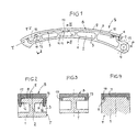
- a tensioning rail S according to FIG. 1, preferably for one Timing chain drive of an internal combustion engine consists of a made of filled or reinforced, especially fiber-reinforced, Plastic one-piece carrier T and a also made of plastic as a prefabricated unit, retrofitted with the carrier T sliding surface body B, made of unfilled plastic with good Slip and fatigue properties can exist.
- the two units T, B are prefabricated separately and together mechanically connected, for example by the two units T, B integrally molded and Force-locking elements. It would also be conceivable to use the sliding lining carrier B subsequently by riveting, screwing, gluing or To mechanically connect welding to the support T.
- the carrier T has a rail-like base body 1 a plurality of transverse passages 3, which are separated by a central partition wall 2 are interrupted. At the right end in Fig. 1 (inlet side one Timing chain) a bearing eye 4 is formed.
- the top of the carrier T forms a curved in this embodiment running, in the transverse direction flat support back 5, behind its end facing the bearing eye 4 a transverse rib 6 is formed with a rounded full cross section.
- the sliding pad carrier B is a band 10 with a smooth working surface 9 and an underside 8.
- One end of the slide pad carrier B has an integrally molded hook end 7, the on the inside a pocket 18, delimited on both sides, for the transverse rib 6 contains.
- Near the end area facing away from the hook end 7 are two side cheeks protruding downwards from the underside 8 15 molded, the lower ends undercut Form locking hooks 16 (Fig. 2).
- B is first the hook end 7 hooked over the transverse rib 6 (Fig. 4) and put the tape on the back 5.
- the side Projections 19 dip into the recesses 13 and become positioned between the stops 14.
- the sidewalls 15 slide with their locking hooks 16 over initial insertion bevels 17 into the pockets 11 until finally the locking hooks 16 reach behind the pocket shoulders 12.
- the sliding lining body B is swinging up to be removed from the carrier T.
Landscapes
- Engineering & Computer Science (AREA)
- General Engineering & Computer Science (AREA)
- Mechanical Engineering (AREA)
- Devices For Conveying Motion By Means Of Endless Flexible Members (AREA)
Description
- Fig. 1
- eine Seitenansicht einer aus vorgefertigten Baueinheiten montierten Spannschiene,
- Fig. 2
- einen Schnitt in der Ebene II-II von Fig. 1, in vergrößertem Maßstab,
- Fig. 3
- einen Schnitt in der Ebene III-III von Fig. 1, in vergrößertem Maßstab, und
- Fig. 4
- einen Schnitt in der Ebene IV-IV in Fig. 1 in vergrößertem Maßstab.
Claims (6)
- Spann- oder Führungsschiene (S) für einen Kettentrieb, insbesondere in einer Brennkraftmaschine, mit einem Träger (T) und einem aus Kunststoff geformten Gleitbelagkörper (B), der mittels Form- und Kraftschlußelementen form -und kraftschlüssig mit dem Träger verbunden ist, wobei der Träger (T) und der Gleitbelagkörper (B) getrennt mit zueinander passenden Form- und Kraftschlußelementen einstückig vorgefertigte Baueinheiten sind und nachträglich mechanisch miteinander verbunden sind, dadurch gekennzeichnet, daß der Träger (T) aus gefülltem oder verstärktem Kunststoff geformt ist.
- Spann- oder Führungsschiene nach Anspruch 1, dadurch gekennzeichnet, daß am Träger (T) an einem Ende eines Tragrückens (5) eine Querrippe (6) angeformt ist;an zumindest einer von der Querrippe (6) in Längsrichtung beabstandeten Stelle beiderseits und unterhalb des Tragrückens (5) Einhak-Taschen (11) mit hinterschnittenen Taschen-Schultern (12) vorgesehen sind;in Ausrichtung auf die Einhak-Taschen (11) über die Unterseite (8) des Gleitbelagkörpers (B) vorstehende Seitenwangen (5) angeformt sind; unddie freien Enden der Seitenwangen (15) zueinander weisende Rasthaken (16) zum Hintergreifen der Taschen-Schultern (12) sind.
- Spann- oder Führungsschiene nach Anspruch 2, dadurch gekennzeichnet, daß die Einhak-Taschen (11) beim der Querrippe (6) abgewandten Endbereich des Tragrückens (5) vorgesehen sind, und daß zwischen den Einhak-Taschen (11) und der Querrippe (6) beiderseits und unterhalb des Tragrückens (5) jeweils mindestens eine durch zwei in Längsrichtung des Tragrückens (5) wirksame Anschläge (14) begrenzte Ausnehmung (13) vorgesehen ist.
- Spann- oder Führungsschiene nach Anspruch 2, dadurch gekennzeichnet, daß die Querrippe (6) an beiden Enden gegenüber der Breitenerstreckung des Tragrückens (5) zurücktritt und einen gerundeten Vollquerschnitt aufweist.
- Spann- oder Führungsschiene nach Anspruch 2, dadurch gekennzeichnet, daß die Einhak-Taschen (11) in Längsrichtung des Trägers (T) weiter sind als die Seitenwangen (15).
- Spann- oder Führungsschiene nach Anspruch 3, dadurch gekennzeichnet, daß am Gleitbelagkörper (B) zwei seitliche, unterseitig vorstehende Vorsprünge (19) angeformt sind, und daß die in Längsrichtung gesehene Weite der Vorsprünge (19) annähernd dem Abstand zwischen den Anschlägen (14) jeder Ausnehmung (13) entspricht.
Applications Claiming Priority (2)
| Application Number | Priority Date | Filing Date | Title |
|---|---|---|---|
| DE29602917U | 1996-02-19 | ||
| DE29602917U DE29602917U1 (de) | 1996-02-19 | 1996-02-19 | Spann- oder Führungsschiene für einen Kettentrieb |
Publications (2)
| Publication Number | Publication Date |
|---|---|
| EP0790436A1 EP0790436A1 (de) | 1997-08-20 |
| EP0790436B1 true EP0790436B1 (de) | 2000-04-26 |
Family
ID=8019716
Family Applications (1)
| Application Number | Title | Priority Date | Filing Date |
|---|---|---|---|
| EP97102423A Revoked EP0790436B1 (de) | 1996-02-19 | 1997-02-14 | Spann- oder Führungsschiene für einen Kettentrieb |
Country Status (4)
| Country | Link |
|---|---|
| US (1) | US5820502A (de) |
| EP (1) | EP0790436B1 (de) |
| JP (1) | JPH09324839A (de) |
| DE (2) | DE29602917U1 (de) |
Families Citing this family (46)
| Publication number | Priority date | Publication date | Assignee | Title |
|---|---|---|---|---|
| JP3162646B2 (ja) * | 1997-03-27 | 2001-05-08 | 株式会社椿本チエイン | テンショナレバー |
| US6013000A (en) * | 1998-08-14 | 2000-01-11 | Tmj Properties, L.L.C. | Polymeric chain guide |
| JP3702359B2 (ja) * | 1999-02-16 | 2005-10-05 | 本田技研工業株式会社 | ブレードテンショナ |
| JP2000257679A (ja) * | 1999-03-05 | 2000-09-19 | Tsubakimoto Chain Co | チェーンガイド |
| JP4558872B2 (ja) * | 1999-11-30 | 2010-10-06 | 大同工業株式会社 | テンショナー等のレバー及びアーム |
| JP2001323976A (ja) * | 2000-05-15 | 2001-11-22 | Honda Motor Co Ltd | チェンガイド部材,チェンガイド部材製造方法およびチェンガイド部材製造装置 |
| JP3243245B1 (ja) * | 2000-11-01 | 2002-01-07 | 株式会社椿本チエイン | 伝動装置用プラスチック製レバー |
| AU2002219842A1 (en) * | 2000-11-17 | 2002-05-27 | Cloyes Gear And Products, Inc. | Snap-fit chain guide with locking connector arrangement |
| JP3253951B1 (ja) * | 2000-12-15 | 2002-02-04 | 株式会社椿本チエイン | 伝動装置用プラスチック製可動ガイド |
| JP3384560B2 (ja) * | 2001-03-13 | 2003-03-10 | 株式会社椿本チエイン | 伝動装置用可動ガイド |
| JP3352669B1 (ja) | 2001-06-13 | 2002-12-03 | アイ・アンド・ピー株式会社 | 伝動装置用サンドイッチ成形ガイド |
| JP3338436B1 (ja) * | 2001-10-02 | 2002-10-28 | 株式会社椿本チエイン | 伝動装置用摺接ガイド |
| JP3516940B2 (ja) * | 2001-10-23 | 2004-04-05 | 株式会社椿本チエイン | 伝動装置用プラスチック製可動ガイド |
| WO2003062668A1 (en) * | 2002-01-23 | 2003-07-31 | Cloyes Gear And Products, Inc. | Snap-fit chain guide |
| US6939259B2 (en) * | 2003-04-25 | 2005-09-06 | Borgwarner Inc. | Two-shot unified chain tensioner arm or guide |
| JP2006250208A (ja) * | 2005-03-09 | 2006-09-21 | Tsubakimoto Chain Co | 伝動装置用ガイド |
| DE102005018901A1 (de) * | 2005-04-22 | 2006-11-16 | Schaeffler Kg | Zugmitteltrieb mit zumindest einer Schiene zum Spannen und/oder Führen eines endlosen Zugmittels |
| DE102005057295A1 (de) * | 2005-12-01 | 2007-06-06 | Schaeffler Kg | Spann- oder Führungsschiene für Zugmittel, insbesondere einen Kettentrieb |
| JP4873971B2 (ja) * | 2006-03-27 | 2012-02-08 | ボルグワーナー・モールステック・ジャパン株式会社 | チェーンテンショナアームおよびチェーンガイド |
| DE102007014668B4 (de) | 2007-03-27 | 2019-05-23 | Iwis Motorsysteme Gmbh & Co. Kg | Spannschienenwippe |
| JP5190160B2 (ja) * | 2007-07-05 | 2013-04-24 | ボーグワーナー インコーポレーテッド | チェーンテンショナまたはチェーンガイド、ならびにそれらの製造方法 |
| JP2009103186A (ja) * | 2007-10-22 | 2009-05-14 | Tsubakimoto Chain Co | 伝動装置用ガイド |
| DE102009000795B4 (de) | 2009-02-12 | 2023-02-23 | Ford Global Technologies, Llc | Spannelement |
| EP2422113B1 (de) * | 2009-02-27 | 2014-03-19 | Borgwarner Inc. | Element für das steuerkettensystem eines fahrzeuges und verfahren dafür |
| JP5611145B2 (ja) * | 2011-08-02 | 2014-10-22 | 株式会社椿本チエイン | 伝動装置用ガイド |
| JP5631825B2 (ja) * | 2011-09-07 | 2014-11-26 | 株式会社椿本チエイン | 伝動装置用ガイド |
| DE202011109363U1 (de) | 2011-12-21 | 2013-03-22 | Iwis Motorsysteme Gmbh & Co. Kg | Spannschiene mit einspritzgegossenem Tragkörper |
| DE102012014943A1 (de) | 2012-07-27 | 2014-01-30 | Iwis Motorsysteme Gmbh & Co. Kg | Spann- oder Führungsschiene mit extrudiertem Gleitbelagkörper |
| DE102012021243A1 (de) | 2012-10-29 | 2014-04-30 | Iwis Motorsysteme Gmbh & Co. Kg | Spannschiene mit extrudiertem Druckstück |
| CN103912642A (zh) * | 2013-01-09 | 2014-07-09 | 广西玉柴机器股份有限公司 | 柴油机链条导轨 |
| DE102013006679A1 (de) * | 2013-04-18 | 2014-10-23 | Iwis Motorsysteme Gmbh & Co. Kg | Spann- oder Führungsschiene mit vernietetem Gleitbelagkörper |
| DE102013221463A1 (de) | 2013-10-23 | 2015-04-23 | Schaeffler Technologies AG & Co. KG | Spannschiene oder Führungsschiene für einen Zugmitteltrieb |
| DE102014205375A1 (de) * | 2014-03-24 | 2015-09-24 | Schaeffler Technologies AG & Co. KG | Führungs- oder Spannschiene mit arretierbarem Gleitbelag |
| DE102014212756A1 (de) * | 2014-07-02 | 2016-01-07 | Schaeffler Technologies AG & Co. KG | Führungs- oder Spannschiene mit arretierbarem Gleitbelag |
| DE102014014719A1 (de) | 2014-10-02 | 2016-04-07 | Iwis Motorsysteme Gmbh & Co. Kg | Spann- oder Führungsschiene mit einem durchgehenden zurückgezogenen Gleitbelagkörper |
| DE102015008877A1 (de) * | 2015-07-08 | 2016-08-04 | Iwis Motorsysteme Gmbh & Co. Kg | Modulare Gleit- oder Spannschiene |
| DE102014014905A1 (de) | 2014-10-08 | 2016-04-14 | Iwis Motorsysteme Gmbh & Co. Kg | Spannschiene mit einem Schmiermittelkanal |
| DE102016002327A1 (de) | 2016-02-26 | 2017-01-19 | Iwis Motorsysteme Gmbh & Co. Kg | Spann- oder Führungsschiene mit einer Ölfangtasche |
| DE102017104385A1 (de) | 2017-03-02 | 2018-09-06 | Iwis Motorsysteme Gmbh & Co. Kg | Spann- oder Führungsschiene mit seitlich umgreifendem Klammerelement |
| DE102017106049A1 (de) | 2017-03-21 | 2017-05-04 | Iwis Motorsysteme Gmbh & Co. Kg | Spann- oder Führungsschiene mit zwei nebeneinander angeordneten Gleitbelagkörpern |
| DE102017109680A1 (de) * | 2017-05-05 | 2018-11-08 | Iwis Motorsysteme Gmbh & Co. Kg | Elastische Führungsschiene |
| JP7177342B2 (ja) * | 2018-10-16 | 2022-11-24 | 株式会社椿本チエイン | チェーンガイド |
| DE102019131314A1 (de) * | 2019-11-20 | 2021-05-20 | Iwis Motorsysteme Gmbh & Co. Kg | Spann- oder Führungsschiene mit einem integrierten Gleitbelag |
| US11466755B2 (en) * | 2020-02-03 | 2022-10-11 | Borgwarner Inc. | Chain guide and tensioning apparatus for vehicles |
| JP7448821B2 (ja) * | 2020-09-29 | 2024-03-13 | 株式会社椿本チエイン | チェーンガイド |
| CN114012979A (zh) * | 2021-12-01 | 2022-02-08 | 伊维氏传动系统(平湖)有限公司 | 一种导轨装配工艺及结构 |
Family Cites Families (7)
| Publication number | Priority date | Publication date | Assignee | Title |
|---|---|---|---|---|
| DE3049106A1 (de) * | 1980-12-24 | 1982-07-08 | Robert Bosch Gmbh, 7000 Stuttgart | Spannschiene fuer kettenantriebe |
| DE3506010A1 (de) * | 1985-02-21 | 1986-08-21 | Feldmühle AG, 4000 Düsseldorf | Spann- oder gleitschiene fuer ketten von kettentrieben |
| DE3706136C1 (de) * | 1987-02-26 | 1988-09-15 | Porsche Ag | Verfahren zur Herstellung eines Kettenspanners |
| JPH0736201Y2 (ja) * | 1989-05-31 | 1995-08-16 | 株式会社椿本チエイン | 合成樹脂製シューを具えたチェーンガイドレール |
| JP2519476Y2 (ja) * | 1991-04-11 | 1996-12-04 | 株式会社椿本チエイン | テンショナレバーのシューの浮上り防止構造 |
| JPH089476Y2 (ja) * | 1991-11-07 | 1996-03-21 | 株式会社椿本チエイン | チェーンガイドのアームとシューの一体化構造 |
| DE4310306A1 (de) * | 1993-03-30 | 1994-10-06 | Bosch Gmbh Robert | Spannschiene |
-
1996
- 1996-02-19 DE DE29602917U patent/DE29602917U1/de not_active Expired - Lifetime
-
1997
- 1997-02-14 DE DE59701492T patent/DE59701492D1/de not_active Revoked
- 1997-02-14 EP EP97102423A patent/EP0790436B1/de not_active Revoked
- 1997-02-18 US US08/801,753 patent/US5820502A/en not_active Expired - Fee Related
- 1997-02-19 JP JP9034725A patent/JPH09324839A/ja active Pending
Also Published As
| Publication number | Publication date |
|---|---|
| DE59701492D1 (de) | 2000-05-31 |
| US5820502A (en) | 1998-10-13 |
| EP0790436A1 (de) | 1997-08-20 |
| JPH09324839A (ja) | 1997-12-16 |
| DE29602917U1 (de) | 1997-06-19 |
Similar Documents
| Publication | Publication Date | Title |
|---|---|---|
| EP0790436B1 (de) | Spann- oder Führungsschiene für einen Kettentrieb | |
| EP0279934B1 (de) | Gleitschiene | |
| EP0956465B1 (de) | Kettenglied mit einschiebbaren trennstegen | |
| DE19728675A1 (de) | Führung für eine kraftübertragende Kette | |
| DE102005062531B4 (de) | Führung für einen Zugmitteltrieb | |
| EP1875107B1 (de) | Zugmitteltrieb mit zumindest einer schiene zum spannen und/oder führen eines endlosen zugmittels | |
| EP1963712A1 (de) | Führungsanordnung für ein umschlingungsmittel und spritzgusswerkzeug zur herstellung einer führungsanordnung | |
| EP0903286B1 (de) | Vorrichtung zum sicheren, formschlüssigen Montieren, Ausrichten und Fixieren von Karosserieteilen | |
| EP3201494B1 (de) | Kettentrieb mit mehreren gleitelementen | |
| EP1099827B1 (de) | Kettenführung für einen Steuerwellenantrieb einer Brennkraftmaschine sowie Verfahren zur Herstellung einer Kettenführung | |
| EP0129248B1 (de) | Schloss für Sicherheitsgurte | |
| DE102014014720A1 (de) | Spann- oder Führungsschiene mit Durchbruch | |
| EP1611927B1 (de) | Schneegleitbrett | |
| EP1561968A1 (de) | Spann- oder Führungsschiene mit Installationskanal | |
| DE10118111A1 (de) | Gurteinfügungsteil | |
| DE10333077A1 (de) | Spann- oder Führungsschiene mit am Tragkörper vorstehendem Rastmittel | |
| EP0793037B1 (de) | Mechanischer Kettenspanner | |
| DE102013004456B3 (de) | Spannschiene mit federndem Aufdrückbereich | |
| DE102013225819A1 (de) | Kettenführung | |
| DE102012221017A1 (de) | Führungseinrichtung für ein Umschlingungsmittel | |
| EP1705401A2 (de) | Kettenglied für eine Energieführungskette | |
| DE19851601A1 (de) | Schiene zum Spannen und/oder Führen einer Kette | |
| DE2735998A1 (de) | Sicherheitsnadel | |
| EP3388317B1 (de) | Kühlfahrzeugaufbau | |
| WO1999003717A1 (de) | Scharniereinrichtung zur schwenkverbindung von fahrzeugaufbauteilen |
Legal Events
| Date | Code | Title | Description |
|---|---|---|---|
| PUAI | Public reference made under article 153(3) epc to a published international application that has entered the european phase |
Free format text: ORIGINAL CODE: 0009012 |
|
| AK | Designated contracting states |
Kind code of ref document: A1 Designated state(s): DE FR GB IT |
|
| 17P | Request for examination filed |
Effective date: 19970728 |
|
| 17Q | First examination report despatched |
Effective date: 19990121 |
|
| GRAG | Despatch of communication of intention to grant |
Free format text: ORIGINAL CODE: EPIDOS AGRA |
|
| GRAG | Despatch of communication of intention to grant |
Free format text: ORIGINAL CODE: EPIDOS AGRA |
|
| GRAH | Despatch of communication of intention to grant a patent |
Free format text: ORIGINAL CODE: EPIDOS IGRA |
|
| GRAH | Despatch of communication of intention to grant a patent |
Free format text: ORIGINAL CODE: EPIDOS IGRA |
|
| GRAA | (expected) grant |
Free format text: ORIGINAL CODE: 0009210 |
|
| AK | Designated contracting states |
Kind code of ref document: B1 Designated state(s): DE FR GB IT |
|
| PG25 | Lapsed in a contracting state [announced via postgrant information from national office to epo] |
Ref country code: IT Free format text: LAPSE BECAUSE OF FAILURE TO SUBMIT A TRANSLATION OF THE DESCRIPTION OR TO PAY THE FEE WITHIN THE PRESCRIBED TIME-LIMIT;WARNING: LAPSES OF ITALIAN PATENTS WITH EFFECTIVE DATE BEFORE 2007 MAY HAVE OCCURRED AT ANY TIME BEFORE 2007. THE CORRECT EFFECTIVE DATE MAY BE DIFFERENT FROM THE ONE RECORDED. Effective date: 20000426 Ref country code: GB Free format text: LAPSE BECAUSE OF FAILURE TO SUBMIT A TRANSLATION OF THE DESCRIPTION OR TO PAY THE FEE WITHIN THE PRESCRIBED TIME-LIMIT Effective date: 20000426 Ref country code: FR Free format text: LAPSE BECAUSE OF FAILURE TO SUBMIT A TRANSLATION OF THE DESCRIPTION OR TO PAY THE FEE WITHIN THE PRESCRIBED TIME-LIMIT Effective date: 20000426 |
|
| REF | Corresponds to: |
Ref document number: 59701492 Country of ref document: DE Date of ref document: 20000531 |
|
| PLBQ | Unpublished change to opponent data |
Free format text: ORIGINAL CODE: EPIDOS OPPO |
|
| EN | Fr: translation not filed | ||
| PLBI | Opposition filed |
Free format text: ORIGINAL CODE: 0009260 |
|
| GBV | Gb: ep patent (uk) treated as always having been void in accordance with gb section 77(7)/1977 [no translation filed] |
Effective date: 20000426 |
|
| 26 | Opposition filed |
Opponent name: ADAM OPEL AG Effective date: 20000906 |
|
| PLBI | Opposition filed |
Free format text: ORIGINAL CODE: 0009260 |
|
| PLBF | Reply of patent proprietor to notice(s) of opposition |
Free format text: ORIGINAL CODE: EPIDOS OBSO |
|
| 26 | Opposition filed |
Opponent name: INA WAELZLAGER SCHAEFFER OHG Effective date: 20010117 Opponent name: ADAM OPEL AG Effective date: 20000906 |
|
| PLBF | Reply of patent proprietor to notice(s) of opposition |
Free format text: ORIGINAL CODE: EPIDOS OBSO |
|
| PLBF | Reply of patent proprietor to notice(s) of opposition |
Free format text: ORIGINAL CODE: EPIDOS OBSO |
|
| PLAB | Opposition data, opponent's data or that of the opponent's representative modified |
Free format text: ORIGINAL CODE: 0009299OPPO |
|
| R26 | Opposition filed (corrected) |
Opponent name: ADAM OPEL AG * 20010117 INA-SCHAEFFLER KG Effective date: 20000906 |
|
| PLAB | Opposition data, opponent's data or that of the opponent's representative modified |
Free format text: ORIGINAL CODE: 0009299OPPO |
|
| PLBQ | Unpublished change to opponent data |
Free format text: ORIGINAL CODE: EPIDOS OPPO |
|
| R26 | Opposition filed (corrected) |
Opponent name: ADAM OPEL AG * 20010117 INA-SCHAEFFLER KG Effective date: 20000906 |
|
| RDAH | Patent revoked |
Free format text: ORIGINAL CODE: EPIDOS REVO |
|
| RTI2 | Title (correction) |
Free format text: TENSION OR GUIDE RAIL FOR A CHAIN TRANSMISSION |
|
| RTI2 | Title (correction) |
Free format text: TENSION OR GUIDE RAIL FOR A CHAIN TRANSMISSION |
|
| APAC | Appeal dossier modified |
Free format text: ORIGINAL CODE: EPIDOS NOAPO |
|
| APAC | Appeal dossier modified |
Free format text: ORIGINAL CODE: EPIDOS NOAPO |
|
| PGFP | Annual fee paid to national office [announced via postgrant information from national office to epo] |
Ref country code: DE Payment date: 20040330 Year of fee payment: 8 |
|
| APBU | Appeal procedure closed |
Free format text: ORIGINAL CODE: EPIDOSNNOA9O |
|
| RDAG | Patent revoked |
Free format text: ORIGINAL CODE: 0009271 |
|
| STAA | Information on the status of an ep patent application or granted ep patent |
Free format text: STATUS: PATENT REVOKED |
|
| 27W | Patent revoked |
Effective date: 20040330 |
|
| APAA | Appeal reference recorded |
Free format text: ORIGINAL CODE: EPIDOS REFN |
|
| APAH | Appeal reference modified |
Free format text: ORIGINAL CODE: EPIDOSCREFNO |
|
| PLAB | Opposition data, opponent's data or that of the opponent's representative modified |
Free format text: ORIGINAL CODE: 0009299OPPO |