EP0785456B1 - Fabrication of optical isolators - Google Patents
Fabrication of optical isolators Download PDFInfo
- Publication number
- EP0785456B1 EP0785456B1 EP97300096A EP97300096A EP0785456B1 EP 0785456 B1 EP0785456 B1 EP 0785456B1 EP 97300096 A EP97300096 A EP 97300096A EP 97300096 A EP97300096 A EP 97300096A EP 0785456 B1 EP0785456 B1 EP 0785456B1
- Authority
- EP
- European Patent Office
- Prior art keywords
- optical
- isolator
- optical isolator
- dicing
- unit
- Prior art date
- Legal status (The legal status is an assumption and is not a legal conclusion. Google has not performed a legal analysis and makes no representation as to the accuracy of the status listed.)
- Expired - Lifetime
Links
- 230000003287 optical effect Effects 0.000 title claims description 120
- 238000004519 manufacturing process Methods 0.000 title claims description 8
- 239000000835 fiber Substances 0.000 claims description 27
- 238000005520 cutting process Methods 0.000 claims description 20
- 239000000853 adhesive Substances 0.000 claims description 14
- 230000001070 adhesive effect Effects 0.000 claims description 14
- 239000013078 crystal Substances 0.000 claims description 14
- 238000000034 method Methods 0.000 claims description 12
- 238000000576 coating method Methods 0.000 claims description 11
- 239000011248 coating agent Substances 0.000 claims description 7
- 230000008878 coupling Effects 0.000 claims description 5
- 238000010168 coupling process Methods 0.000 claims description 5
- 238000005859 coupling reaction Methods 0.000 claims description 5
- 238000004026 adhesive bonding Methods 0.000 claims description 2
- 230000010287 polarization Effects 0.000 description 23
- 239000000463 material Substances 0.000 description 12
- 239000011521 glass Substances 0.000 description 11
- 230000001419 dependent effect Effects 0.000 description 9
- 238000010586 diagram Methods 0.000 description 9
- XUIMIQQOPSSXEZ-UHFFFAOYSA-N Silicon Chemical compound [Si] XUIMIQQOPSSXEZ-UHFFFAOYSA-N 0.000 description 7
- 229910052710 silicon Inorganic materials 0.000 description 7
- 239000010703 silicon Substances 0.000 description 7
- 239000004593 Epoxy Substances 0.000 description 6
- GWEVSGVZZGPLCZ-UHFFFAOYSA-N Titan oxide Chemical compound O=[Ti]=O GWEVSGVZZGPLCZ-UHFFFAOYSA-N 0.000 description 5
- 239000013307 optical fiber Substances 0.000 description 5
- 239000000919 ceramic Substances 0.000 description 3
- 230000032798 delamination Effects 0.000 description 3
- 238000005516 engineering process Methods 0.000 description 3
- 238000002955 isolation Methods 0.000 description 3
- VYPSYNLAJGMNEJ-UHFFFAOYSA-N Silicium dioxide Chemical compound O=[Si]=O VYPSYNLAJGMNEJ-UHFFFAOYSA-N 0.000 description 2
- 230000005540 biological transmission Effects 0.000 description 2
- 238000002592 echocardiography Methods 0.000 description 2
- 230000002411 adverse Effects 0.000 description 1
- 230000004888 barrier function Effects 0.000 description 1
- 229910052797 bismuth Inorganic materials 0.000 description 1
- JCXGWMGPZLAOME-UHFFFAOYSA-N bismuth atom Chemical group [Bi] JCXGWMGPZLAOME-UHFFFAOYSA-N 0.000 description 1
- 230000000694 effects Effects 0.000 description 1
- 238000005530 etching Methods 0.000 description 1
- 238000001914 filtration Methods 0.000 description 1
- 238000005304 joining Methods 0.000 description 1
- CPLXHLVBOLITMK-UHFFFAOYSA-N magnesium oxide Inorganic materials [Mg]=O CPLXHLVBOLITMK-UHFFFAOYSA-N 0.000 description 1
- 239000000395 magnesium oxide Substances 0.000 description 1
- AXZKOIWUVFPNLO-UHFFFAOYSA-N magnesium;oxygen(2-) Chemical compound [O-2].[Mg+2] AXZKOIWUVFPNLO-UHFFFAOYSA-N 0.000 description 1
- 239000010979 ruby Substances 0.000 description 1
- 229910001750 ruby Inorganic materials 0.000 description 1
- -1 rutile Chemical compound 0.000 description 1
- 229910052594 sapphire Inorganic materials 0.000 description 1
- 239000010980 sapphire Substances 0.000 description 1
- 239000004065 semiconductor Substances 0.000 description 1
- 239000000377 silicon dioxide Substances 0.000 description 1
- 235000012239 silicon dioxide Nutrition 0.000 description 1
- 238000005549 size reduction Methods 0.000 description 1
- 239000004408 titanium dioxide Substances 0.000 description 1
- 239000002699 waste material Substances 0.000 description 1
Images


Classifications
-
- G—PHYSICS
- G02—OPTICS
- G02F—OPTICAL DEVICES OR ARRANGEMENTS FOR THE CONTROL OF LIGHT BY MODIFICATION OF THE OPTICAL PROPERTIES OF THE MEDIA OF THE ELEMENTS INVOLVED THEREIN; NON-LINEAR OPTICS; FREQUENCY-CHANGING OF LIGHT; OPTICAL LOGIC ELEMENTS; OPTICAL ANALOGUE/DIGITAL CONVERTERS
- G02F1/00—Devices or arrangements for the control of the intensity, colour, phase, polarisation or direction of light arriving from an independent light source, e.g. switching, gating or modulating; Non-linear optics
- G02F1/01—Devices or arrangements for the control of the intensity, colour, phase, polarisation or direction of light arriving from an independent light source, e.g. switching, gating or modulating; Non-linear optics for the control of the intensity, phase, polarisation or colour
- G02F1/09—Devices or arrangements for the control of the intensity, colour, phase, polarisation or direction of light arriving from an independent light source, e.g. switching, gating or modulating; Non-linear optics for the control of the intensity, phase, polarisation or colour based on magneto-optical elements, e.g. exhibiting Faraday effect
- G02F1/093—Devices or arrangements for the control of the intensity, colour, phase, polarisation or direction of light arriving from an independent light source, e.g. switching, gating or modulating; Non-linear optics for the control of the intensity, phase, polarisation or colour based on magneto-optical elements, e.g. exhibiting Faraday effect used as non-reciprocal devices, e.g. optical isolators, circulators
-
- G—PHYSICS
- G02—OPTICS
- G02B—OPTICAL ELEMENTS, SYSTEMS OR APPARATUS
- G02B6/00—Light guides; Structural details of arrangements comprising light guides and other optical elements, e.g. couplings
- G02B6/24—Coupling light guides
- G02B6/42—Coupling light guides with opto-electronic elements
- G02B6/4201—Packages, e.g. shape, construction, internal or external details
- G02B6/4204—Packages, e.g. shape, construction, internal or external details the coupling comprising intermediate optical elements, e.g. lenses, holograms
- G02B6/4207—Packages, e.g. shape, construction, internal or external details the coupling comprising intermediate optical elements, e.g. lenses, holograms with optical elements reducing the sensitivity to optical feedback
- G02B6/4208—Packages, e.g. shape, construction, internal or external details the coupling comprising intermediate optical elements, e.g. lenses, holograms with optical elements reducing the sensitivity to optical feedback using non-reciprocal elements or birefringent plates, i.e. quasi-isolators
-
- Y—GENERAL TAGGING OF NEW TECHNOLOGICAL DEVELOPMENTS; GENERAL TAGGING OF CROSS-SECTIONAL TECHNOLOGIES SPANNING OVER SEVERAL SECTIONS OF THE IPC; TECHNICAL SUBJECTS COVERED BY FORMER USPC CROSS-REFERENCE ART COLLECTIONS [XRACs] AND DIGESTS
- Y10—TECHNICAL SUBJECTS COVERED BY FORMER USPC
- Y10S—TECHNICAL SUBJECTS COVERED BY FORMER USPC CROSS-REFERENCE ART COLLECTIONS [XRACs] AND DIGESTS
- Y10S359/00—Optical: systems and elements
- Y10S359/90—Methods
-
- Y—GENERAL TAGGING OF NEW TECHNOLOGICAL DEVELOPMENTS; GENERAL TAGGING OF CROSS-SECTIONAL TECHNOLOGIES SPANNING OVER SEVERAL SECTIONS OF THE IPC; TECHNICAL SUBJECTS COVERED BY FORMER USPC CROSS-REFERENCE ART COLLECTIONS [XRACs] AND DIGESTS
- Y10—TECHNICAL SUBJECTS COVERED BY FORMER USPC
- Y10S—TECHNICAL SUBJECTS COVERED BY FORMER USPC CROSS-REFERENCE ART COLLECTIONS [XRACs] AND DIGESTS
- Y10S372/00—Coherent light generators
- Y10S372/703—Optical isolater
Definitions
- the invention relates to light transmission systems, more particularly, to an optical isolator.
- Polarization-dependent isolators using linear polarizers together with Faraday rotators are well known.
- the state of the art for polarization-independent isolators using spatial walkoff polarizers is discussed in K.W. Chang, W. V. Sorin, Polarization Independent Isolator Using Spatial Walkoff Polarizers, IEEE Photonics Technology Letters, Vol. 1, No. 3 (March 1989); and in K. W. Chang, W. V. Sorin, High-Performance Single-Mode Fiber Polarization-Independent Isolators , Optics Letters, Vol. 15, No. 8 (April 1990).
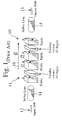
- FIG. 1 shows a state of the art isolator 10, in which light from an input single-mode fiber 12 is focused by a first selfocTM lens 14 to an isolator 11, and thence through a second lens 15 to an output single-mode fiber 13.
- a magnetic field 18 is associated with the isolator.
- Non-reciprocal Faraday rotation in the isolator 11 is provided by bismuth substituted YIG films (Bi-YIG) which typically operate in the 1.3 and 1.55 ⁇ m wavelength range and typically provide 45° of Faraday rotation in thicknesses of less than 500 ⁇ m.
- Birefringent TiO 2 i.e., rutile, crystals are used to provide a spatial walkoff for extraordinary polarization travelling through the isolator.
- the polarizers in the isolator are typically realized by using the spatial walkoff from the birefringent crystals combined with the spatial filtering provided by the single-mode fiber.
- the crystals may be slightly angled and the fiber end faces may be polished, for example at an angle of 6°, to reduce back reflections from the internal surface of the isolator.
- Such isolators are quite large because the isolator is actually composed of individual pieces. Such structure is sometimes referred to as a "freespace" structure. The various pieces of the isolator are each placed in a separate holder and are then AR-coated to air. Thus, for each isolator it is necessary to assemble each crystal, where each crystal has a different orientation.
- isolators examples include the Freespace Interfaced Fiber Isolator (package size 3.8 mm ⁇ 13 mm), Laser Interfaced Fiber Isolator (package size 3.5 ⁇ 23.5 mm), Miniature Optic Freespace Isolator (package size 3.0 mm ⁇ 1.5 mm - one stage; 3.0 mm ⁇ 3.0 mm - two stage), and Polarization Insensitive Miniature Optic Freespace Isolator (package size 4.0 mm ⁇ 5.0 mm), each of which is manufactured by E-Tek Dynamics, Inc.
- EP-A-0,512,572 discloses an optical isolator and method for fabricating the same in which a polarizer, a Faraday rotator and an analyzer are fixed by fused glass applied on an outer periphery of the analyzer to be contacted with the Faraday rotator. No adhesive exists between contact planes of the polarizer and the Faraday rotator and those of the Faraday rotator and the analyzer. The assembled isolator structure is cut to form small isolator units. The features of the preamble of claim 1 are known from that document.
- assembly of the prior art isolator requires the steps of arranging the individual crystals in the holder in a specific orientation. It is therefore necessary to have an alignment mark for each crystal. If the isolator is made small in size, then it is very difficult to arrange the individual elements into a complete, properly aligned isolator. Additionally, it is difficult to handle the assembled isolator.
- the present invention seeks to provide an improved method of fabricating an optical isolator.
- the preferred embodiment can provide small, low-cost optical isolators for both polarization-independent and polarization-dependent applications.
- the preferred embodiment provides a preassembled, low-cost optical isolator having the capability of large optical isolators.
- An optical isolator unit is assembled and subsequently diced into smaller isolator chips for placement in a micro-optical bench, such as a silicon or ceramic bench, along with input and an output fiber coupling AR-coated ball lenses.
- a micro-optical bench such as a silicon or ceramic bench
- larger birefringence walkoff crystals and a 45° Faraday rotator are first aligned and then glued together with an optical-grade epoxy.
- polarizers and a 45° Faraday rotator are first aligned and then glued together with an optical-grade epoxy.
- the surfaces of the components Prior to gluing, the surfaces of the components are AR-coated to match the index of the optical epoxy.
- An optical isolator unit formed in this manner is then diced into smaller isolator chips with a high-speed wafer saw.
- the optical isolator unit is mounted on any one of its sides in such a way that only a smallest possible cutting depth is required for dicing, i.e., it is mounted such that a thinnest dimension of the isolator is presented for cutting.
- the preferred embodiment can provide an optical isolator in which the material cost is reduced.
- the isolator chips can be very small, it is possible to place them on a micro-optical bench between a pair of coupling AR-coated ball lenses, which further reduces the size requirement of each isolator chip.
- the use of a micro-optical bench allows precise, passive positioning of the optical components.
- the preferred technique for fabricating the described isolator chips can also reduce the handling costs associated with the assembly of several small isolator components into a completed assembly by aligning and preassembling the isolator components in a large isolator assembly, and by subsequently dicing the large assembly into several small isolator chips. In this way, only a single alignment step and assembly step is required to produce isolator chips. In this way, only a single alignment step and assembly step is required to produce several optical isolators.
- the preferred embodiment can allow for a reduction of cost for fiber collimators, as well as providing improved, cost reduced, polarization-dependent/independent isolators for laser diodes and fiber transmission systems.
- optical isolator unit is aligned, assembled, and subsequently diced into smaller isolator chips for placement in a micro-optical bench, such as a silicon or ceramic bench, along with input and output fiber coupling AR-coated ball lenses.
- the optical isolator unit is preferably comprised of one or more larger birefringence walkoff crystals that are first aligned and then glued with an optical-grade adhesive, such as an optical-grade epoxy, to one or more 45° Faraday rotators.
- optical-grade adhesive such as an optical-grade epoxy
- the preferred embodiment may comprise an optical isolator unit, such as that disclosed by K. W. Chang, Optical Nonreciprocal Device, U. S. Patent No. 4,974,944 (4 December 1990), although the principles taught herein can be readily applied to other types of optical isolators. See, also K. W. Chang, Polarization Preserving Optical Isolator, U.S. Patent No. 5,446.578 (29 August 1995).
- An optical isolator unit formed in this manner typically exhibits a rectangular cross section when such section is taken along a longitudinal axis of the optical isolator unit.
- the surfaces of the components are preferably antirefraction (AR) coated to match the index of the optical-grade adhesive.
- AR coating provides an index-matching coating that corrects for a refractive index difference between two adjoining mediums.
- the actual AR coating used depends on the system in which the coating is required. For example, a thin layer of a material such as magnesium oxide, titanium dioxide, and silicon dioxide is deposited on the surface of a high refractive index material to allow a particular wavelength or band of wavelengths to pass without significant reflection. Multiple coatings may be placed onto the surface to match the material to other wavelengths.
- AR coatings are well known in the art, see for example The Handbook of Optical Coatings for Fiber Optic Devices, Evaporated Coatings, Inc.
- the AR coating is provided to match the refractive index of each component of the optical isolator unit to that of the optical-grade adhesive that holds the optical isolator unit components together. Therefore, instead of matching the index of air, which is 1, the AR coating matches the optical-grade adhesive index, which is closer to that of glass, i.e., about 1.52.
- the optical-grade adhesive may be replaced by any known optical-grade adhesive material, such as an optical-grade epoxy.
- the optical isolator unit is diced into smaller isolator chips using a high-speed wafer saw or other such dicing devices as may be known in the art.
- the optical isolator unit is mounted on any one of its sides in such a way that only a smallest possible cutting depth is required for dicing, i.e., it is mounted such that a thinnest possible dimension of the isolator is presented for cutting. This procedure reduces material loss due to cutting and prevents delamination of the small isolator chips that are produced by such cutting.
- Fig. 2 is a block schematic diagram of a first preferred embodiment of optical isolator 20.
- An input single-mode optical fiber 21 provides a light source that is coupled via the optical isolator to an output single-mode optical fiber 22.
- this embodiment is useful for a fiber-to-fiber application.
- optical isolator Since this type of isolator is used in optical systems that only allow light to travel in one direction, light enters the isolator through an AR-coated glass 24 that is secured to the input single-mode fiber 21 by an index-matching adhesive 23, such as an optical grade epoxy. Light enters a first AR-coated ball lens 25 and is focused thereby to an optical isolator chip 26.
- the AR-coated ball lenses 25, 27 and optical isolator chip 26 are all preferably mounted on a micro-optical bench 29 that is fashioned in such way that the various optical isolator components are securely held in an aligned configuration.
- the optical isolator chip 26 is a one-way light transmitting device, in which any light that is reflected back along the optical path misses the input single-mode fiber. Accordingly, no light is reflected back to the input single-mode fiber.
- the optical isolator chip 26 operates in conjunction with a magnet (not shown) that produces a magnetic field B 28 to provide a non-reciprocal characteristic to the isolator.
- a magnet not shown
- the preferred embodiment uses either a very small external magnet or the optical isolator may be positioned inside, and surrounded by, a larger magnet, depending on the preferred package design.
- the active area of the optical isolator chip is very small, i.e., 200 ⁇ m ⁇ 200 ⁇ m.
- this embodiment can provide a significant size reduction when compared to conventional optical isolators, which are typically on the order of 2 mm ⁇ 2 mm.
- an optical isolator unit is preferably formed by carefully aligning the isolator components, and then joining the isolator components with an index-matching adhesive, where each element so joined is AR-coated to match the index of the element to the index of the adhesive.
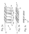
- Figs. 3a-3c show the dicing steps that are used to produce a polarization-independent optical isolator chip from a larger, optical isolator unit.
- Each component of the optical isolator unit is AR-coated before the various components are aligned and glued together.
- a layer of glass is provided at either end of the optical isolator unit on which the outer-facing side of the glass is AR-coated for air.
- the optical isolator unit may also include an AR-coated glass cover slide 37, 38 that has a refractive index that matches that of the optical-grade adhesive which is used to secure the various optical isolator unit components together.
- the elements of the optical isolator unit 36 i.e., the AR-coated glass cover slides 37, 38, walkoff crystals 35a, 35b, 35c, 35d and Faraday rotator 39a, 39b, discussed above, are aligned and then glued together.
- the resulting optical isolator unit is typically 2 mm ⁇ 2 mm ⁇ 7.3 mm in size.
- the preferred dicing method dices the optical isolator unit 36 into smaller pieces that each ultimately comprise an individual optical isolator chip.
- the optical isolator unit is mounted on any one of its sides in such a way that only a smallest possible cutting depth is required for dicing, i.e., it is mounted such that a thinnest possible dimension of the isolator is presented for cutting. This procedure reduces material loss due to cutting and prevents delamination of the isolator chips that are produced by such cutting.
- a wafer saw is first used to cut the optical isolator unit 36 into four isolator pieces along the lines 31 in the direction shown by the lines 30 (Fig. 3a).
- the cutting depth during the first dicing operation is 2 mm, resulting in a cutting loss of about 150 ⁇ m of material.
- the isolator assembly is cut into four 2 mm ⁇ 0.3875 mm ⁇ 7.3 mm isolator pieces.
- the four isolator pieces formed by the first cutting operation are then each cut as shown by the lines 33 in the direction shown by the lines 32 (Fig. 3b).
- the cutting depth for this operation is 0.4 mm, producing a loss of material of 100 ⁇ m due to the cutting operation.
- each optical isolator chip is 0.45 mm ⁇ 0.3875 mm ⁇ 7.3 mm.
- the costs associated with producing such optical isolators provide a substantial economy that otherwise are not achieved in the prior art because only one alignment and one assembly operation are required to produce several optical isolators. Additionally, very small optical isolators may be produced without the need for time consuming and therefore expensive micro-manufacturing and alignment operations. Such costs savings are relative to the particular optical isolator produced.
- the optical isolator chips 26 are placed in an etched portion of a silicon bench 29 or micro-optical bench, as shown in Fig. 2.
- the silicon bench is also etched to provide a location for placing each of the AR-coated ball lenses 25 and 27, such that the isolator assembly 20 is readily formed with each component thereof in precise alignment, one component to the other.
- the silicon bench is readily batch processed on a silicon wafer by etching appropriate patterns onto the wafer that predefine with precision the location of the lens and the location of the optical isolator chips.
- the ball lens allows the fabrication of a smaller isolation assembly 20 because such lens is able to accommodate a smaller optical isolator.
- the ball lens is preferably made of glass or any other optical material having a high refractive index, e.g., ruby or sapphire.
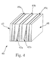
- Fig. 4 is a block diagram of a polarization-dependent optical isolator unit from which isolator chips can be made.
- an optical isolator unit 46 i.e., the AR-coated cover slides 47, 48, polarizers 49a, 49b, 49c, and Faraday rotator 45a, 45b are aligned and then glued together.
- the polarizers may be any appropriate polarizers, such as part no. is 1550-HC-0° manufactured by Corning, Inc., Advanced Product Department, Corning, NY.
- the optical isolator unit is then processed as discussed above for the polarization-independent isolator of Figs. 2 and 3a-3c.
- Fig. 5 is a block schematic diagram of a second embodiment of optical isolator assembly 50.
- This embodiment combines a laser source 51, such as a laser diode, and a ball lens 54, with a polarization-dependent optical isolator chip 56 of the type that is produced from the optical isolator unit 46, as discussed above in connection with Fig. 4.
- the laser source, ball lens, and optical isolator chip are mounted to a micro-optical bench 59 and coupled to a single-mode fiber 52 by a second ball lens 57.
- the system also includes an AR-coated glass cover slide 53 that is mounted directly to the single-mode fiber 52.
- Fig. 6 is a block diagram of an embodiment of a single-mode fiber platform.
- the optical isolator assembly 60 includes a single-mode fiber 61 to which an optical isolator chip 62 is glued.
- the optical isolator chip includes a single AR-coated glass cover slide 65. Light produced by a laser diode 64 is coupled through a lens 63 to the optical isolator chip 62.
- an optical isolator chip can be produced in which the material waste and cost is reduced.
- the optical isolator chips are very small. It is possible to place such optical isolators on a micro-optical bench, such as a silicon or ceramic bench, between a coupling AR-coated ball lens, which further reduces the size requirement of each optical isolator chip.
- the technique for fabricating the herein described optical isolator chips reduces the handling cost associated with the alignment and assembly of several small optical isolator components into a completed assembly by preassembling the optical isolator components in a large optical isolator unit, and by subsequently dicing the large optical isolator unit into several small optical isolator chips. This can thus allow for a reduction of cost for fiber collimators, as well as providing improved, cost-reduced, polarization-dependent optical isolators for laser diode and semiconductor amplifiers.
Landscapes
- Physics & Mathematics (AREA)
- General Physics & Mathematics (AREA)
- Optics & Photonics (AREA)
- Nonlinear Science (AREA)
- Engineering & Computer Science (AREA)
- Power Engineering (AREA)
Applications Claiming Priority (2)
| Application Number | Priority Date | Filing Date | Title |
|---|---|---|---|
| US08/588,042 US5808793A (en) | 1996-01-17 | 1996-01-17 | Low-cost compact optical isolators |
| US588042 | 1996-01-17 |
Publications (2)
| Publication Number | Publication Date |
|---|---|
| EP0785456A1 EP0785456A1 (en) | 1997-07-23 |
| EP0785456B1 true EP0785456B1 (en) | 2004-05-26 |
Family
ID=24352229
Family Applications (1)
| Application Number | Title | Priority Date | Filing Date |
|---|---|---|---|
| EP97300096A Expired - Lifetime EP0785456B1 (en) | 1996-01-17 | 1997-01-09 | Fabrication of optical isolators |
Country Status (4)
| Country | Link |
|---|---|
| US (1) | US5808793A (enExample) |
| EP (1) | EP0785456B1 (enExample) |
| JP (1) | JP4008064B2 (enExample) |
| DE (1) | DE69729230T2 (enExample) |
Families Citing this family (28)
| Publication number | Priority date | Publication date | Assignee | Title |
|---|---|---|---|---|
| JPH09214024A (ja) * | 1996-02-02 | 1997-08-15 | Fanuc Ltd | 固体レーザ発振装置 |
| US6130778A (en) * | 1997-04-17 | 2000-10-10 | Tdk Corporation | Composite optical element, optical isolator, optical circulator, optical switch and process for producing them |
| DE19725720A1 (de) * | 1997-06-18 | 1998-12-24 | Alsthom Cge Alcatel | Optischer Isolator und Wellenlängenmuliplexer-Modul mit integriertem optischen Isolator |
| JP2002511974A (ja) * | 1997-06-26 | 2002-04-16 | コーニング インコーポレイテッド | 光学素子およびそれらの組立て方法 |
| US6043933A (en) * | 1997-11-21 | 2000-03-28 | Hewlett-Packard Company | Split optical element and a low cost fabrication approach |
| US6075642A (en) * | 1998-06-18 | 2000-06-13 | Hewlett-Packard Company | Multi-port optical isolator |
| US6064522A (en) * | 1998-06-23 | 2000-05-16 | Lucent Technologies Inc | Miniature mass producible non-reciprocal devices |
| US6055101A (en) * | 1998-08-28 | 2000-04-25 | Lucent Technologies, Inc. | Isolator assembly and method of making |
| US6226115B1 (en) * | 1998-09-30 | 2001-05-01 | Fujitsu Limited | Optical circulator or switch having a birefringent wedge positioned between faraday rotators |
| US6600601B1 (en) * | 1999-04-12 | 2003-07-29 | Shin-Etsu Chemical Co., Ltd. | Polarization-independent optical isolator and production method thereof |
| JP2001125047A (ja) | 1999-10-27 | 2001-05-11 | Minebea Co Ltd | 光アイソレータ |
| JP4351339B2 (ja) * | 1999-10-28 | 2009-10-28 | 株式会社精工技研 | 光部品の製造方法 |
| US6373644B1 (en) * | 1999-11-15 | 2002-04-16 | Axsun Technologies, Inc. | Micro optical bench component clip structures |
| WO2002069029A1 (en) * | 2001-02-28 | 2002-09-06 | Board Of Control Of Michigan Technological University | Magneto-photonic crystal isolators |
| US20030031395A1 (en) * | 2001-08-10 | 2003-02-13 | Youfu Shao | High isolation gain flattening filter |
| US7263247B1 (en) | 2002-02-11 | 2007-08-28 | Gemfire Corporation | Integrated optical isolator array |
| US6580842B1 (en) | 2002-02-11 | 2003-06-17 | Markus P. Hehlen | Integrated optical circulator array |
| US6560387B1 (en) | 2002-02-11 | 2003-05-06 | Markus P. Hehlen | Doped fiber amplifier utilizing integrated circulator array |
| JPWO2004046798A1 (ja) * | 2002-11-15 | 2006-04-27 | 住友金属鉱山株式会社 | 磁気光学素子とその製造方法およびこの磁気光学素子が組み込まれた光アイソレータ |
| US7511901B2 (en) * | 2003-06-30 | 2009-03-31 | Micha Zimmermann | Micro-optic alignment system |
| US7801702B2 (en) * | 2004-02-12 | 2010-09-21 | Lockheed Martin Corporation | Enhanced diagnostic fault detection and isolation |
| DE202011107213U1 (de) | 2011-10-27 | 2011-12-16 | Rudi Danz | Optische Isolatoren mit spektraler Lichtwandlung und Erzeugung von Laserstrahlung |
| US9921377B2 (en) | 2014-07-31 | 2018-03-20 | Hewlett Packard Enterprise Department LP | Interposer registration elements |
| WO2016201625A1 (zh) * | 2015-06-16 | 2016-12-22 | 华为技术有限公司 | 一种准直透镜以及包括其的光模块 |
| JP6978719B2 (ja) * | 2016-10-24 | 2021-12-08 | 日本電気硝子株式会社 | 磁気光学素子及びその製造方法 |
| CN111176000B (zh) * | 2020-02-18 | 2024-02-09 | 河南鑫宇光科技股份有限公司 | 一种提高光学隔离器隔离度的方法 |
| CN113281922A (zh) * | 2021-05-21 | 2021-08-20 | 中国科学院半导体研究所 | 光发射模块 |
| JP7634500B2 (ja) * | 2022-05-09 | 2025-02-21 | 信越化学工業株式会社 | 光アイソレータ |
Citations (1)
| Publication number | Priority date | Publication date | Assignee | Title |
|---|---|---|---|---|
| US5040863A (en) * | 1988-11-02 | 1991-08-20 | Tokyo Electrical Co., Inc. | Optical isolator |
Family Cites Families (15)
| Publication number | Priority date | Publication date | Assignee | Title |
|---|---|---|---|---|
| JPS57100410A (en) | 1980-12-15 | 1982-06-22 | Fujitsu Ltd | Optical isolator |
| US4974944A (en) * | 1988-07-21 | 1990-12-04 | Hewlett-Packard Company | Optical nonreciprocal device |
| US4981341A (en) * | 1989-07-14 | 1991-01-01 | At&T Bell Laboratories | Apparatus comprising a magneto-optic isolator utilizing a garnet layer |
| JP2849655B2 (ja) * | 1990-02-22 | 1999-01-20 | 株式会社トーキン | 光アイソレータの製造方法 |
| JPH03284713A (ja) * | 1990-03-30 | 1991-12-16 | Hitachi Cable Ltd | 光ファイバ型アイソレータ |
| JP2628774B2 (ja) * | 1990-04-20 | 1997-07-09 | 株式会社日立製作所 | 光アイソレータ内蔵形半導体レーザモジュール |
| JPH04338916A (ja) * | 1990-08-06 | 1992-11-26 | Kyocera Corp | 光アイソレータ用素子及び該光アイソレータ用素子を用いた光アイソレータ,半導体レーザモジュール |
| US5267077A (en) * | 1990-11-05 | 1993-11-30 | At&T Bell Laboratories | Spherical multicomponent optical isolator |
| JP2697354B2 (ja) * | 1991-05-10 | 1998-01-14 | 日本電気株式会社 | 光アイソレータの製造方法 |
| US5325456A (en) * | 1992-02-12 | 1994-06-28 | E.I. Du Pont De Nemours And Company | Optical isolator in an optical fiber feedthrough |
| JP2757093B2 (ja) * | 1992-04-20 | 1998-05-25 | 富士電気化学株式会社 | 無偏波分散型光アイソレータ |
| JPH0774343A (ja) * | 1993-08-31 | 1995-03-17 | Fujitsu Ltd | 集積化光装置及びその製造方法 |
| DE4431285C1 (de) * | 1994-09-02 | 1995-12-07 | Ant Nachrichtentech | Lasermodul |
| JP3439275B2 (ja) * | 1994-11-25 | 2003-08-25 | エヌイーシートーキン株式会社 | 光アイソレータの製造方法 |
| KR100286956B1 (ko) * | 1994-12-27 | 2001-04-16 | 도낀 가부시끼가이샤 | 광 아이솔레이터용 광학 소자 조립체 및 그 제조방법 |
-
1996
- 1996-01-17 US US08/588,042 patent/US5808793A/en not_active Expired - Lifetime
-
1997
- 1997-01-09 EP EP97300096A patent/EP0785456B1/en not_active Expired - Lifetime
- 1997-01-09 DE DE69729230T patent/DE69729230T2/de not_active Expired - Lifetime
- 1997-01-14 JP JP00455197A patent/JP4008064B2/ja not_active Expired - Lifetime
Patent Citations (1)
| Publication number | Priority date | Publication date | Assignee | Title |
|---|---|---|---|---|
| US5040863A (en) * | 1988-11-02 | 1991-08-20 | Tokyo Electrical Co., Inc. | Optical isolator |
Also Published As
| Publication number | Publication date |
|---|---|
| JP4008064B2 (ja) | 2007-11-14 |
| DE69729230T2 (de) | 2005-06-23 |
| US5808793A (en) | 1998-09-15 |
| DE69729230D1 (de) | 2004-07-01 |
| EP0785456A1 (en) | 1997-07-23 |
| JPH09197345A (ja) | 1997-07-31 |
Similar Documents
| Publication | Publication Date | Title |
|---|---|---|
| EP0785456B1 (en) | Fabrication of optical isolators | |
| US5267077A (en) | Spherical multicomponent optical isolator | |
| US6862383B2 (en) | Arrayed optical device | |
| EP0383923B1 (en) | Polarizing isolation apparatus and optical isolator using the same | |
| JP2774467B2 (ja) | 偏波無依存型光アイソレータ装置 | |
| US6249619B1 (en) | Optical isolator | |
| US5040863A (en) | Optical isolator | |
| US20030044102A1 (en) | Fiberoptic polarizer and method of making the same | |
| KR20000015885A (ko) | 광 아이솔레이터 | |
| US6270261B1 (en) | Semiconductor laser module | |
| JP4548988B2 (ja) | 光アイソレータ付きレセプタクルとその組立方法 | |
| JP2542532B2 (ja) | 偏光無依存型光アイソレ―タの製造方法 | |
| US7043101B1 (en) | Integrated optical pump module | |
| US6043933A (en) | Split optical element and a low cost fabrication approach | |
| JPH0246419A (ja) | 光アイソレータ | |
| JP2000241763A (ja) | 光アイソレータ | |
| JP2002156530A (ja) | 光アイソレータ付き光ファイバピグテイル | |
| JP2001125043A (ja) | 光アイソレータ | |
| JPH10339848A (ja) | 偏光無依存光アイソレータ | |
| US20050207010A1 (en) | Optical isolator and method of producing the same | |
| JPH02201314A (ja) | 光アイソレータ | |
| JPH01281402A (ja) | 偏光ビームスプリツタと光アイソレータ | |
| JPH11249072A (ja) | 偏光子及びそれを用いた光アイソレータ | |
| WO2000049450A2 (en) | Optical circulator | |
| JP2002228982A (ja) | 光アイソレータ |
Legal Events
| Date | Code | Title | Description |
|---|---|---|---|
| PUAI | Public reference made under article 153(3) epc to a published international application that has entered the european phase |
Free format text: ORIGINAL CODE: 0009012 |
|
| AK | Designated contracting states |
Kind code of ref document: A1 Designated state(s): DE FR GB |
|
| 17P | Request for examination filed |
Effective date: 19980123 |
|
| 17Q | First examination report despatched |
Effective date: 20001006 |
|
| RAP1 | Party data changed (applicant data changed or rights of an application transferred) |
Owner name: HEWLETT-PACKARD COMPANY, A DELAWARE CORPORATION |
|
| RAP1 | Party data changed (applicant data changed or rights of an application transferred) |
Owner name: AGILENT TECHNOLOGIES INC. |
|
| RAP1 | Party data changed (applicant data changed or rights of an application transferred) |
Owner name: AGILENT TECHNOLOGIES INC. A DELAWARE CORPORATION |
|
| RAP1 | Party data changed (applicant data changed or rights of an application transferred) |
Owner name: AGILENT TECHNOLOGIES, INC. (A DELAWARE CORPORATION |
|
| GRAP | Despatch of communication of intention to grant a patent |
Free format text: ORIGINAL CODE: EPIDOSNIGR1 |
|
| RTI1 | Title (correction) |
Free format text: FABRICATION OF OPTICAL ISOLATORS |
|
| RTI1 | Title (correction) |
Free format text: FABRICATION OF OPTICAL ISOLATORS |
|
| GRAS | Grant fee paid |
Free format text: ORIGINAL CODE: EPIDOSNIGR3 |
|
| GRAA | (expected) grant |
Free format text: ORIGINAL CODE: 0009210 |
|
| AK | Designated contracting states |
Kind code of ref document: B1 Designated state(s): DE FR GB |
|
| REG | Reference to a national code |
Ref country code: GB Ref legal event code: FG4D |
|
| REF | Corresponds to: |
Ref document number: 69729230 Country of ref document: DE Date of ref document: 20040701 Kind code of ref document: P |
|
| PGFP | Annual fee paid to national office [announced via postgrant information from national office to epo] |
Ref country code: FR Payment date: 20050117 Year of fee payment: 9 |
|
| ET | Fr: translation filed | ||
| PLBE | No opposition filed within time limit |
Free format text: ORIGINAL CODE: 0009261 |
|
| STAA | Information on the status of an ep patent application or granted ep patent |
Free format text: STATUS: NO OPPOSITION FILED WITHIN TIME LIMIT |
|
| 26N | No opposition filed |
Effective date: 20050301 |
|
| PG25 | Lapsed in a contracting state [announced via postgrant information from national office to epo] |
Ref country code: FR Free format text: LAPSE BECAUSE OF NON-PAYMENT OF DUE FEES Effective date: 20060131 |
|
| REG | Reference to a national code |
Ref country code: GB Ref legal event code: 732E |
|
| REG | Reference to a national code |
Ref country code: FR Ref legal event code: ST Effective date: 20060929 |
|
| PGFP | Annual fee paid to national office [announced via postgrant information from national office to epo] |
Ref country code: GB Payment date: 20070125 Year of fee payment: 11 |
|
| GBPC | Gb: european patent ceased through non-payment of renewal fee |
Effective date: 20080109 |
|
| PG25 | Lapsed in a contracting state [announced via postgrant information from national office to epo] |
Ref country code: GB Free format text: LAPSE BECAUSE OF NON-PAYMENT OF DUE FEES Effective date: 20080109 |
|
| REG | Reference to a national code |
Ref country code: DE Ref legal event code: R082 Ref document number: 69729230 Country of ref document: DE Representative=s name: DILG HAEUSLER SCHINDELMANN PATENTANWALTSGESELL, DE |
|
| REG | Reference to a national code |
Ref country code: DE Ref legal event code: R082 Ref document number: 69729230 Country of ref document: DE Representative=s name: DILG HAEUSLER SCHINDELMANN PATENTANWALTSGESELL, DE Effective date: 20130628 Ref country code: DE Ref legal event code: R081 Ref document number: 69729230 Country of ref document: DE Owner name: AVAGO TECHNOLOGIES GENERAL IP (SINGAPORE) PTE., SG Free format text: FORMER OWNER: AVAGO TECHNOLOGIES FIBER IP (SINGAPORE) PTE. LTD., SINGAPORE, SG Effective date: 20130628 |
|
| PGFP | Annual fee paid to national office [announced via postgrant information from national office to epo] |
Ref country code: DE Payment date: 20151217 Year of fee payment: 20 |
|
| REG | Reference to a national code |
Ref country code: DE Ref legal event code: R071 Ref document number: 69729230 Country of ref document: DE |