EP0784728B1 - Fermeture de batiment - Google Patents
Fermeture de batiment Download PDFInfo
- Publication number
- EP0784728B1 EP0784728B1 EP95928980A EP95928980A EP0784728B1 EP 0784728 B1 EP0784728 B1 EP 0784728B1 EP 95928980 A EP95928980 A EP 95928980A EP 95928980 A EP95928980 A EP 95928980A EP 0784728 B1 EP0784728 B1 EP 0784728B1
- Authority
- EP
- European Patent Office
- Prior art keywords
- fire
- frame
- profiles
- glass pane
- fire protection
- Prior art date
- Legal status (The legal status is an assumption and is not a legal conclusion. Google has not performed a legal analysis and makes no representation as to the accuracy of the status listed.)
- Expired - Lifetime
Links
Images


Classifications
-
- E—FIXED CONSTRUCTIONS
- E06—DOORS, WINDOWS, SHUTTERS, OR ROLLER BLINDS IN GENERAL; LADDERS
- E06B—FIXED OR MOVABLE CLOSURES FOR OPENINGS IN BUILDINGS, VEHICLES, FENCES OR LIKE ENCLOSURES IN GENERAL, e.g. DOORS, WINDOWS, BLINDS, GATES
- E06B5/00—Doors, windows, or like closures for special purposes; Border constructions therefor
- E06B5/10—Doors, windows, or like closures for special purposes; Border constructions therefor for protection against air-raid or other war-like action; for other protective purposes
- E06B5/16—Fireproof doors or similar closures; Adaptations of fixed constructions therefor
- E06B5/165—Fireproof windows
-
- E—FIXED CONSTRUCTIONS
- E06—DOORS, WINDOWS, SHUTTERS, OR ROLLER BLINDS IN GENERAL; LADDERS
- E06B—FIXED OR MOVABLE CLOSURES FOR OPENINGS IN BUILDINGS, VEHICLES, FENCES OR LIKE ENCLOSURES IN GENERAL, e.g. DOORS, WINDOWS, BLINDS, GATES
- E06B5/00—Doors, windows, or like closures for special purposes; Border constructions therefor
- E06B5/10—Doors, windows, or like closures for special purposes; Border constructions therefor for protection against air-raid or other war-like action; for other protective purposes
- E06B5/16—Fireproof doors or similar closures; Adaptations of fixed constructions therefor
- E06B5/164—Sealing arrangements between the door or window and its frame, e.g. intumescent seals specially adapted therefor
-
- E—FIXED CONSTRUCTIONS
- E06—DOORS, WINDOWS, SHUTTERS, OR ROLLER BLINDS IN GENERAL; LADDERS
- E06B—FIXED OR MOVABLE CLOSURES FOR OPENINGS IN BUILDINGS, VEHICLES, FENCES OR LIKE ENCLOSURES IN GENERAL, e.g. DOORS, WINDOWS, BLINDS, GATES
- E06B3/00—Window sashes, door leaves, or like elements for closing wall or like openings; Layout of fixed or moving closures, e.g. windows in wall or like openings; Features of rigidly-mounted outer frames relating to the mounting of wing frames
- E06B3/04—Wing frames not characterised by the manner of movement
- E06B3/263—Frames with special provision for insulation
- E06B2003/26394—Strengthening arrangements in case of fire
Definitions
- the invention relates to a building closure consisting of a frame and at least one wing pivotally held in the frame, for example a Door leaf or a window sash that has a frame in which a fire-resistant fire protection glass pane, a sheet part with heat-insulating Interlayer or another, at least for a certain period of time fire-resistant insert is arranged, the frame and / or the frame two aluminum profiles or the like from here considered Fire protection area does not consist of fire-resistant materials Intermediate layer of the fire protection glass pane, the sheet part or the like are interconnected, and being between the profiles of the frame and / or the frame thermal separation elements, preferably Fire protection panels are arranged, being between the frame and the sash as well as between the frame and that used in the frame Fire protection glass, the sheet part or the like when heated expanding elements are arranged, which when heated a refractory Bridge between the fire-resistant components, namely the Form fire protection glass pane or the leaf part and the fire protection plates, the elements that expand when heated exert forces on the exert fire-resistant
- DE-PS 3 050 946 discloses a fire protection component for such Building closures, such as windows, doors or the like, which two Has aluminum profile strips, which via a thermal separating element load-bearing core are interconnected, being for the frame filling Retaining strips made of steel are provided, which are anchored to the core by means of screws are.
- a building closure is already known from this publication, which can be produced in particular from aluminum, the Aluminum can melt at least on the fire side without losing stability of the building closure is significantly impaired. The stability of this The building is then closed by the thermal separation elements and made the retaining strips.
- the thermal separation elements are included the holding strips and the holding strips with the frame filling, for example with connected to a fire protection glass pane.
- Disadvantage of this prior art Construction is, however, that a great deal of construction has to be done, since the retaining strips have to be connected to the separating elements.
- this this known construction provides for the use of screws.
- the object of the invention based on creating a generic building closure that at Exposure to fire despite the almost exclusive use of light metal, such as aluminum or the like or plastics a sufficient temporary Stability with simultaneous partitioning has, the construction of the Building closure should be as simple and therefore inexpensive to manufacture should and with one-sided heating sufficient mobility of the two shells has, due to a relative movement of individual components to allow different extents.
- the sheet part or the like expanding elements arranged when heated, which a when heated Refractory bridge between the refractory components, namely the Form fire protection glass pane or the leaf part and the fire protection plates, the elements that expand when heated exert forces on the exert fire-resistant components which are substantially perpendicular to them Surface normals run so that after the frame and / or Frame profiles a cohesion of these components due to tension these components are given by means of the elements.
- the frame and sash or elements arranged between two casements of a double casement window such that the arranged in the frame of the frame and sash Fire protection panels over the elements that expand when heated are interconnected.
- the elements that expand when heated thus create a bridge between the fire protection panels or between one Fire protection plate and a fire protection glass pane, which is at
- heating-expanding elements in a manner known per se can also perform sealing functions, in that the entire gap between the frame and the sash or between two sashes one double-leaf window or a double-leaf door is sealed.
- a building closure that is sufficient temporary Stability with simultaneous partitioning.
- this is Building end construction designed such that a simple and therefore inexpensive manufacture of the building closure is possible without heat resistant thermal elements with holding strips for one Fire protection glass pane or a sheet part must be screwed.
- the fire protection panels are between adjacent connecting elements arranged, which connect the profiles. Which changes when heated expansive elements are on the narrow sides of the fire protection panels and / or arranged on the thermal connecting elements.
- Heating expansion elements arranged so that when exposed to fire adjacent fire protection panels or fire protection glass panes or Sheet parts connected by means of the elements that expand when heated be that an essentially flat building closure is achieved.
- the force is exerted by those that expand when heated Elements on the fire protection panels or the fire protection glass pane or that Blade part essentially perpendicular to the surface normal of these components.
- the connecting elements are in particular not thermally conductive, preferably made of Plastic, especially made of polyamide, and formed at its ends dovetail-shaped and reach into corresponding ones Recesses in the profiles.
- the elements that expand when exposed to heat can both advantageously on the frame side as well as the wing side on both vertical sections and be arranged in the door frame area, so that by expanding the Elements of the fire protection glass pane or the sheet part and the fire protection plates loaded in essentially perpendicular directions of force are, in particular the advantage is achieved that these components on their Entire edge lengths are clamped in such a way that a twist of the Components are avoided, which may lead to leaks, in particular could lead to a smoke and gas seal.
- the fire protection glass pane can heat up in the direction of its Extend surface normals. This will further increase the Bracing of the fire protection glass pane in those that expand when exposed to heat Achieved elements, thereby increasing the stability of the Building closure is achieved in the event of a fire.
- the profiles in such a way are interconnected that they are at least limited under fire can be moved towards or away from each other to thermal stresses to compensate for one-sided heating.
- thermal Tensions can be balanced with one-sided heating.
- At least one profile displaceable at least to a limited extent in the longitudinal direction of the connecting elements is stored.
- the "floating" storage of at least one Profile due to a limited sliding arrangement of the Connecting element in this profile, so that the profile along the or the connecting elements to or from the opposite profile opposite profile is movable away.
- connecting elements with one profile and the opposite arranged profile in the form of a shear stress loose connection are loosely attached. This configuration ensures maximum stability of the building closure with limited mobility the profiles to each other, in case one Exposure to fire.
- the connecting elements in cross section essentially V-shaped recesses in the Profiles are held, the recesses in their Cross-sectional shape essentially with the ends of the connecting elements match and in the longitudinal direction of the connecting elements are open on both sides.
- the connecting elements are essentially at their ends dovetail-shaped, so that the corresponding Recesses also in cross section are dovetail-shaped.
- This recess is one Recess closed on one side so that it has the shape of a undercut groove.
- the one opposite this recess Recess is according to this feature of the invention open on both sides in the longitudinal direction of the connecting elements educated.
- this recess has the shape of a Bore, the bore in cross section also dovetail-shaped is trained. That in this recess arranged connecting element is thus at least in one Direction limited sliding, so that the Profile with the open recesses along the connecting elements is held displaceably.
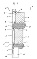
- FIG. 1 There is a building closure 1 shown in FIG. 1 from a frame 2 and a door leaf 3, the frame 2 fixed with a masonry of a building, not shown is connected and the door leaf 3 is pivotable about an axis of rotation is arranged on the frame 2.
- the frame 2 has two oppositely arranged Aluminum profiles 4 and 5, which as box profiles with are essentially rectangular in cross section. There is a fire protection plate between the aluminum profiles 4 and 5 6 arranged, the fire protection plate 6 for example connected to the aluminum profiles 4 and 5 can be.
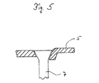
- Connecting elements 7 arranged as plastic pins are made of polyamide, which are dovetail-shaped Have ends and in corresponding recesses 8 in engage the aluminum profiles 4 and 5.
- Such fasteners 7 consist accordingly of a non-thermally conductive Material and are over at regular intervals the entire longitudinal extent of the aluminum profiles 4 and 5 arranged so that the aluminum profiles 4 and 5, the fire protection plate 6 and the connecting elements 7 a fire protection component form, which in the present case as Frame 2 is formed.
- the connecting elements 7th are plate-shaped, so that the fire protection plate 6 covered on both sides by a continuous plate is.
- the door leaf 3 also consists of aluminum profiles 9 and 10, which are also substantially box-shaped are essentially rectangular in cross section. It can be seen that the aluminum profile 10 on its the frame 2 facing away from a web 11 and that on the aluminum profile 9 a substantially L-shaped Profile bar 12 is fastened from aluminum, the longer leg 13 aligned with the web 11 is, the web 11 and the leg 13 at their free Each end have a seal 14, between which one Fire protection glass pane 15 is arranged.
- the aluminum profiles 9 and 10 of the door leaf 3 are also connected to one another via connecting elements 7.
- a fire protection plate 16 is inserted into the cavity, the fire protection plate 16, as in the case of aluminum profiles 4 and 5 of the frame 2, with the aluminum profiles 9 and 10 connected, for example glued, can be.
- a cavity 19 is present between the leg 13 and the frame 2 facing away Ends of the aluminum profiles 9 and 10 of the door leaf 3 . Protrudes into this cavity 19 the fire protection glass pane held between the seals 14 5 with their end 20 in such a way that both their Narrow side and both visible sides are free.
- Elements 21 are arranged in the cavities 17 and 19, that expand when exposed to heat. These elements 21 are on the narrow sides of the fire protection panels 6 and 16 attached or lie on the connecting elements 7. But it is also conceivable that the elements 21 exclusively are arranged on the connecting elements 7 if these are designed as plate-shaped elements and the Narrow sides of the fire protection panels 6 or 16 completely cover.
- the elements 21 are in the present exemplary embodiment trained in such a way that they cover the entire area extend the vertical length of the frame 2 or the door leaf 3 and also in the door frame area, d. H. between the two vertical profiles of the frame 2 (in the head area) are present.
- the building closure 1 according to Figure 1 is beginning Exposure to fire, d. H. Heat exposure shown. It can be seen that those that expand when heated Elements 21 have expanded so that the cavities 17 and 19 essentially through the elements 21 are filled in, the elements 21 being a bridge between the fire protection plates 6, 16 or between the fire protection plate 16 and the fire protection glass panel 15.
- the Fire protection glass pane 15 is in the area of this End 20 of the expanding element 21 at their three free pages.
- the expanding elements 21 generate in the direction of the fire protection plates 6, 16 or 15 forces on the fire protection glass pane, so that this component to be tense with each other.
- At the time of in Figure 2 shown state is the construction of Frame 2 and door leaf 3 not yet affected by fire.
- a stable unity is formed, which over a certain Period withstands the effects of fire.
- the building 1 is further Fire exposure shown, being recognized is that the fire protection glass 15 in the direction of Has extended surface normals, so that thereby further increase in forces between element 21 and Fire protection glass pane 15 is effected.
- the elements 21 from a swelling under the influence of heat Sodium silicate based material.
- such elements under the trademark "Palusol" available on the market. These elements have in their of Heat unaffected in any way in any way Way mechanical holding forces in the present Problem necessary size to transfer.
- the building closure 1 according to the present invention can therefore completely do without steel components, so that the building closure 1 only from the material components Aluminum and the material of the fire protection panels 6, 16 or the fire protection glass pane 15 is instructed. About that In addition, only elements 21 based on sodium silicate are left used.
- the connecting elements 7 in the aluminum profiles 4 and 10 are arranged in the recesses 8, the are formed in the form of an undercut groove.
- the dovetail ends of the connecting elements 7 are thus firmly clamped in these recesses, so that the connecting elements 7 have no degree of freedom in them Have recesses 8.
- the connecting elements 7 are thus in the recesses 8 the aluminum profiles 5 and 9 stored such that they at least limited movement in the aluminum profiles 5 and 9 are attached.
- This allows the opposite Aluminum profiles 4 and 5 on the one hand and 9 and 10 on the other in the event of fire and the associated different extents at different distances aluminum profiles arranged on top of each other at the source of the fire be moved to or away from each other, so that the building 1 if exposed to fire for a long time has sufficient stability that one-sided Heating and the associated "bimetal effect" impaired could be.
Claims (4)
- Fermeture d'immeuble composée d'une feuillure et d'au moins un battant monté de manière pivotante dans la feuillure, par exemple un panneau de porte ou de fenêtre comportant un châssis muni d'une vitre réfractaire de protection contre l'incendie, d'un élément de panneau avec une couche intermédiaire d'isolation thermique ou d'une autre garniture résistant au feu au moins pendant un certain temps,caractérisée en ce quela feuillure et/ou le châssis étant formés de deux profilés en aluminium ou moyens analogues en matériau non résistant au feu dans le domaine de protection contre le feu considéré ici, et qui sont reliés avec interposition d'une vitre de protection contre le feu de la partie de panneau ou d'un moyen analogue, etentre les profilés (4, 5, 9, 10) de la feuillure (2) et/ou du châssis il y a des éléments de coupure thermique, de préférence des plaques de protection contre le feu (6, 16),entre la feuillure (2) et le battant ainsi qu'entre le châssis, et la vitre de protection contre le feu (15), la partie de panneau, ou le moyen analogue, placé dans le châssis, il y a des éléments (21) se dilatant par élévation de température et qui, lors d'une élévation de température, forment un pont réfractaire entre les pièces résistant au feu, à savoir la vitre de protection contre le feu (15) ou la partie de panneau, et les plaques de protection contre le feu (6, 16),les éléments (21) qui se dilatent par élévation de température exerçant des efforts sur les composants résistant au feu (6, 15, 16), ces efforts étant essentiellement perpendiculaires à la normale aux surfaces, de sorte qu'après fusion des profilés de feuillure et/ou de châssis, on a une tenue de ces composants (6, 15, 16) du fait de leur serrage (6, 15, 16) par les éléments (21), etles plaques de protection contre le feu (6, 16) étant prévues entre des éléments de liaison voisins (7) reliant les profilés (4, 5, 9, 10),
les profilés (4, 5, 9, 10) sont reliés de manière mobile relative pour se rapprocher ou s'écarter, de manière au moins limitée, sous l'effet du feu, et compenser les contraintes thermiques en cas d'élévation de température d'un seul côté. - Fermeture d'immeuble selon la revendication 1,
caractérisée en ce qu'
au moins un profilé (4, 5, 9, 10) est monté coulissant au moins de manière limitée dans la direction longitudinale des éléments de liaison (7). - Fermeture d'immeuble selon la revendication 1,
caractérisée en ce que
les éléments de liaison (7) sont fixés de manière solide avec un profilé (4, 10) et de manière libre, par une liaison libre, chaque fois avec le profilé (5, 9) opposé, sous la forme d'une liaison libre vis-à-vis des contraintes de coulissement. - Fermeture d'immeuble selon la revendication 1,
caractérisée en ce que
les éléments de liaison (7) sont tenus dans des cavités (8) à section essentiellement en forme de V dans les profilés (5, 9),
les cavités (8) correspondant pour l'essentiel, par la forme de leur section, à la forme des extrémités des éléments de liaison (7), en étant ouvertes aux deux extrémités dans la direction longitudinale des éléments de liaison (7).
Applications Claiming Priority (5)
| Application Number | Priority Date | Filing Date | Title |
|---|---|---|---|
| DE4430647 | 1994-08-29 | ||
| DE19944430647 DE4430647A1 (de) | 1994-08-29 | 1994-08-29 | Gebäudeabschluss |
| DE19515421A DE19515421A1 (de) | 1994-08-29 | 1995-04-26 | Gebäudeabschluß |
| DE19515421 | 1995-04-26 | ||
| PCT/DE1995/001132 WO1996007005A1 (fr) | 1994-08-29 | 1995-08-24 | Fermeture de batiment |
Publications (2)
| Publication Number | Publication Date |
|---|---|
| EP0784728A1 EP0784728A1 (fr) | 1997-07-23 |
| EP0784728B1 true EP0784728B1 (fr) | 1999-08-04 |
Family
ID=25939631
Family Applications (1)
| Application Number | Title | Priority Date | Filing Date |
|---|---|---|---|
| EP95928980A Expired - Lifetime EP0784728B1 (fr) | 1994-08-29 | 1995-08-24 | Fermeture de batiment |
Country Status (10)
| Country | Link |
|---|---|
| EP (1) | EP0784728B1 (fr) |
| AT (1) | ATE182954T1 (fr) |
| CZ (1) | CZ55197A3 (fr) |
| DE (2) | DE19515421A1 (fr) |
| FI (1) | FI970773A (fr) |
| HU (1) | HUT76901A (fr) |
| NO (1) | NO970834L (fr) |
| PL (1) | PL318907A1 (fr) |
| SK (1) | SK26397A3 (fr) |
| WO (1) | WO1996007005A1 (fr) |
Families Citing this family (8)
| Publication number | Priority date | Publication date | Assignee | Title |
|---|---|---|---|---|
| AT412494B (de) * | 2003-06-25 | 2005-03-25 | Alutechnik Matauschek Gmbh | Flügel- und/oder stockrahmen |
| PL224169B1 (pl) * | 2011-01-11 | 2016-11-30 | Fakro Pp Spółka Z Ograniczoną Odpowiedzialnością | Zamknięcie ogniochronne otworu w przegrodzie budowlanej, zwłaszcza otworu ze schodami składanymi |
| JP6182350B2 (ja) * | 2013-04-26 | 2017-08-16 | 三和シヤッター工業株式会社 | 断熱建具 |
| CH708354B1 (de) * | 2013-07-16 | 2017-08-31 | Saint Gobain | Brandschutzbauteil |
| CN104847222A (zh) * | 2015-04-15 | 2015-08-19 | 江苏申阳交通装备有限公司 | 高寒无霜节能型轨道列车车窗 |
| JP2018127792A (ja) * | 2017-02-07 | 2018-08-16 | Ykk Ap株式会社 | 建具 |
| JP6894549B2 (ja) * | 2017-02-24 | 2021-06-30 | Ykk Ap株式会社 | 建具 |
| CN114278206A (zh) * | 2020-09-28 | 2022-04-05 | 重庆美心贝斯特门窗股份有限公司 | 一种断桥铝合金窗隔热耐火扇结构 |
Family Cites Families (1)
| Publication number | Priority date | Publication date | Assignee | Title |
|---|---|---|---|---|
| DE4232312A1 (de) * | 1992-09-26 | 1994-03-31 | Trube & Kings Kg | Feuerhemmendes Bauteil |
-
1995
- 1995-04-26 DE DE19515421A patent/DE19515421A1/de not_active Withdrawn
- 1995-08-24 AT AT95928980T patent/ATE182954T1/de not_active IP Right Cessation
- 1995-08-24 PL PL95318907A patent/PL318907A1/xx unknown
- 1995-08-24 DE DE59506544T patent/DE59506544D1/de not_active Expired - Lifetime
- 1995-08-24 HU HU9701432A patent/HUT76901A/hu unknown
- 1995-08-24 EP EP95928980A patent/EP0784728B1/fr not_active Expired - Lifetime
- 1995-08-24 SK SK263-97A patent/SK26397A3/sk unknown
- 1995-08-24 WO PCT/DE1995/001132 patent/WO1996007005A1/fr not_active Application Discontinuation
- 1995-08-24 CZ CZ97551A patent/CZ55197A3/cs unknown
-
1997
- 1997-02-24 FI FI970773A patent/FI970773A/fi unknown
- 1997-02-25 NO NO970834A patent/NO970834L/no unknown
Also Published As
| Publication number | Publication date |
|---|---|
| SK26397A3 (en) | 1997-07-09 |
| ATE182954T1 (de) | 1999-08-15 |
| FI970773A0 (fi) | 1997-02-24 |
| EP0784728A1 (fr) | 1997-07-23 |
| DE19515421A1 (de) | 1996-10-31 |
| WO1996007005A1 (fr) | 1996-03-07 |
| NO970834D0 (no) | 1997-02-25 |
| NO970834L (no) | 1997-04-21 |
| CZ55197A3 (en) | 1997-07-16 |
| HUT76901A (en) | 1997-12-29 |
| DE59506544D1 (de) | 1999-09-09 |
| FI970773A (fi) | 1997-04-23 |
| PL318907A1 (en) | 1997-07-21 |
Similar Documents
| Publication | Publication Date | Title |
|---|---|---|
| EP1566514B1 (fr) | Vitrage pare-feu en plusieurs parties avec un dormant pour fenêtre ou porte | |
| AT4249U1 (de) | Brandschutztür oder -fenster | |
| DE3009729A1 (de) | Bauteil (bauelement) | |
| AT4250U1 (de) | Brandschutztür mit einem diese umfassenden türstock | |
| DE19635409B4 (de) | Glastür für Brandschutzzwecke sowie Verfahren zum Herstellen einer Glastür für Brandschutzzwecke | |
| DE102012010028A1 (de) | Rahmenanordnung für ein sektionaltorpaneel | |
| EP0784728B1 (fr) | Fermeture de batiment | |
| DE3402226C1 (de) | Verbundprofil fuer einen Fluegel- oder Blendrahmen fuer Fenster oder verglaste Tueren | |
| DE2932812C2 (de) | Flügel- und Blendrahmen für Fenster oder verglaste Türen | |
| DE2437296C2 (de) | Hohlprofilleiste | |
| EP2743438B1 (fr) | Dispositif pour l'agencement de vitres sur un châssis de fenêtre, une methode pour agencer un tel dispositif sur un châssis de fenêtre, et utilisation du dispositif pour l'isolation thermique et phonique. | |
| DE202012101540U1 (de) | Zargenfreie Brandschutz-Ganzglastür | |
| DE19730033A1 (de) | Blend- und/oder Flügelrahmen eines Fensters/einer Tür | |
| EP0093265A2 (fr) | Fenêtre métallique | |
| EP2312104A1 (fr) | Porte coupe-feu | |
| DE2855360A1 (de) | Verbundfenster | |
| AT9854U1 (de) | Brandschutz-bauelement für tür- oder fensterflügel | |
| DE202005007514U1 (de) | Rahmen für ein Fenster oder eine Tür | |
| DE3604433C1 (en) | Door leaf or window sash and frame configured in a bulletproof manner | |
| EP1435424B1 (fr) | Paroi vitrée | |
| EP0746658B1 (fr) | Dispositif isolant pour façades | |
| EP0059916B1 (fr) | Chambranle, dont le chant a des parties collées | |
| DE10251431A1 (de) | Haustür | |
| DE4430647A1 (de) | Gebäudeabschluss | |
| EP0738818B1 (fr) | Fenêtre à vitrage isolant |
Legal Events
| Date | Code | Title | Description |
|---|---|---|---|
| PUAI | Public reference made under article 153(3) epc to a published international application that has entered the european phase |
Free format text: ORIGINAL CODE: 0009012 |
|
| 17P | Request for examination filed |
Effective date: 19970324 |
|
| AK | Designated contracting states |
Kind code of ref document: A1 Designated state(s): AT BE CH DE DK ES FR GB GR IE IT LI NL PT SE |
|
| 17Q | First examination report despatched |
Effective date: 19971020 |
|
| GRAG | Despatch of communication of intention to grant |
Free format text: ORIGINAL CODE: EPIDOS AGRA |
|
| GRAG | Despatch of communication of intention to grant |
Free format text: ORIGINAL CODE: EPIDOS AGRA |
|
| GRAH | Despatch of communication of intention to grant a patent |
Free format text: ORIGINAL CODE: EPIDOS IGRA |
|
| GRAH | Despatch of communication of intention to grant a patent |
Free format text: ORIGINAL CODE: EPIDOS IGRA |
|
| GRAA | (expected) grant |
Free format text: ORIGINAL CODE: 0009210 |
|
| AK | Designated contracting states |
Kind code of ref document: B1 Designated state(s): AT BE CH DE DK ES FR GB GR IE IT LI NL PT SE |
|
| PG25 | Lapsed in a contracting state [announced via postgrant information from national office to epo] |
Ref country code: SE Free format text: THE PATENT HAS BEEN ANNULLED BY A DECISION OF A NATIONAL AUTHORITY Effective date: 19990804 Ref country code: NL Free format text: LAPSE BECAUSE OF FAILURE TO SUBMIT A TRANSLATION OF THE DESCRIPTION OR TO PAY THE FEE WITHIN THE PRESCRIBED TIME-LIMIT Effective date: 19990804 Ref country code: GR Free format text: LAPSE BECAUSE OF NON-PAYMENT OF DUE FEES Effective date: 19990804 Ref country code: GB Free format text: LAPSE BECAUSE OF FAILURE TO SUBMIT A TRANSLATION OF THE DESCRIPTION OR TO PAY THE FEE WITHIN THE PRESCRIBED TIME-LIMIT Effective date: 19990804 Ref country code: ES Free format text: THE PATENT HAS BEEN ANNULLED BY A DECISION OF A NATIONAL AUTHORITY Effective date: 19990804 |
|
| REF | Corresponds to: |
Ref document number: 182954 Country of ref document: AT Date of ref document: 19990815 Kind code of ref document: T |
|
| REG | Reference to a national code |
Ref country code: CH Ref legal event code: EP |
|
| PG25 | Lapsed in a contracting state [announced via postgrant information from national office to epo] |
Ref country code: AT Free format text: LAPSE BECAUSE OF NON-PAYMENT OF DUE FEES Effective date: 19990824 |
|
| PG25 | Lapsed in a contracting state [announced via postgrant information from national office to epo] |
Ref country code: LI Free format text: LAPSE BECAUSE OF NON-PAYMENT OF DUE FEES Effective date: 19990831 Ref country code: CH Free format text: LAPSE BECAUSE OF NON-PAYMENT OF DUE FEES Effective date: 19990831 Ref country code: BE Free format text: LAPSE BECAUSE OF NON-PAYMENT OF DUE FEES Effective date: 19990831 |
|
| REF | Corresponds to: |
Ref document number: 59506544 Country of ref document: DE Date of ref document: 19990909 |
|
| ET | Fr: translation filed | ||
| REG | Reference to a national code |
Ref country code: IE Ref legal event code: FG4D Free format text: GERMAN |
|
| ITF | It: translation for a ep patent filed |
Owner name: SOCIETA' ITALIANA BREVETTI S.P.A. |
|
| PG25 | Lapsed in a contracting state [announced via postgrant information from national office to epo] |
Ref country code: PT Free format text: LAPSE BECAUSE OF FAILURE TO SUBMIT A TRANSLATION OF THE DESCRIPTION OR TO PAY THE FEE WITHIN THE PRESCRIBED TIME-LIMIT Effective date: 19991104 Ref country code: DK Free format text: LAPSE BECAUSE OF FAILURE TO SUBMIT A TRANSLATION OF THE DESCRIPTION OR TO PAY THE FEE WITHIN THE PRESCRIBED TIME-LIMIT Effective date: 19991104 |
|
| NLV1 | Nl: lapsed or annulled due to failure to fulfill the requirements of art. 29p and 29m of the patents act | ||
| GBV | Gb: ep patent (uk) treated as always having been void in accordance with gb section 77(7)/1977 [no translation filed] |
Effective date: 19990804 |
|
| BERE | Be: lapsed |
Owner name: HORMANN K.G. ECKELHAUSEN Effective date: 19990831 |
|
| REG | Reference to a national code |
Ref country code: CH Ref legal event code: PL |
|
| PLBE | No opposition filed within time limit |
Free format text: ORIGINAL CODE: 0009261 |
|
| STAA | Information on the status of an ep patent application or granted ep patent |
Free format text: STATUS: NO OPPOSITION FILED WITHIN TIME LIMIT |
|
| REG | Reference to a national code |
Ref country code: IE Ref legal event code: FD4D |
|
| 26N | No opposition filed | ||
| PGFP | Annual fee paid to national office [announced via postgrant information from national office to epo] |
Ref country code: DE Payment date: 20140822 Year of fee payment: 20 |
|
| PGFP | Annual fee paid to national office [announced via postgrant information from national office to epo] |
Ref country code: FR Payment date: 20140819 Year of fee payment: 20 |
|
| PGFP | Annual fee paid to national office [announced via postgrant information from national office to epo] |
Ref country code: IT Payment date: 20140825 Year of fee payment: 20 |
|
| REG | Reference to a national code |
Ref country code: DE Ref legal event code: R071 Ref document number: 59506544 Country of ref document: DE |