EP0778566B1 - Apparatus and method for synthesising an information signal and a reproduction control signal and information signal recording apparatus - Google Patents
Apparatus and method for synthesising an information signal and a reproduction control signal and information signal recording apparatus Download PDFInfo
- Publication number
- EP0778566B1 EP0778566B1 EP96308568A EP96308568A EP0778566B1 EP 0778566 B1 EP0778566 B1 EP 0778566B1 EP 96308568 A EP96308568 A EP 96308568A EP 96308568 A EP96308568 A EP 96308568A EP 0778566 B1 EP0778566 B1 EP 0778566B1
- Authority
- EP
- European Patent Office
- Prior art keywords
- information
- sub
- code
- signal
- synthesis signal
- Prior art date
- Legal status (The legal status is an assumption and is not a legal conclusion. Google has not performed a legal analysis and makes no representation as to the accuracy of the status listed.)
- Expired - Lifetime
Links
Images


Classifications
-
- G—PHYSICS
- G11—INFORMATION STORAGE
- G11B—INFORMATION STORAGE BASED ON RELATIVE MOVEMENT BETWEEN RECORD CARRIER AND TRANSDUCER
- G11B20/00—Signal processing not specific to the method of recording or reproducing; Circuits therefor
- G11B20/10—Digital recording or reproducing
-
- G—PHYSICS
- G11—INFORMATION STORAGE
- G11B—INFORMATION STORAGE BASED ON RELATIVE MOVEMENT BETWEEN RECORD CARRIER AND TRANSDUCER
- G11B20/00—Signal processing not specific to the method of recording or reproducing; Circuits therefor
- G11B20/00086—Circuits for prevention of unauthorised reproduction or copying, e.g. piracy
- G11B20/00884—Circuits for prevention of unauthorised reproduction or copying, e.g. piracy involving a watermark, i.e. a barely perceptible transformation of the original data which can nevertheless be recognised by an algorithm
- G11B20/00913—Circuits for prevention of unauthorised reproduction or copying, e.g. piracy involving a watermark, i.e. a barely perceptible transformation of the original data which can nevertheless be recognised by an algorithm based on a spread spectrum technique
-
- G—PHYSICS
- G11—INFORMATION STORAGE
- G11B—INFORMATION STORAGE BASED ON RELATIVE MOVEMENT BETWEEN RECORD CARRIER AND TRANSDUCER
- G11B20/00—Signal processing not specific to the method of recording or reproducing; Circuits therefor
- G11B20/00086—Circuits for prevention of unauthorised reproduction or copying, e.g. piracy
-
- G—PHYSICS
- G11—INFORMATION STORAGE
- G11B—INFORMATION STORAGE BASED ON RELATIVE MOVEMENT BETWEEN RECORD CARRIER AND TRANSDUCER
- G11B20/00—Signal processing not specific to the method of recording or reproducing; Circuits therefor
- G11B20/10—Digital recording or reproducing
- G11B20/10527—Audio or video recording; Data buffering arrangements
-
- H—ELECTRICITY
- H04—ELECTRIC COMMUNICATION TECHNIQUE
- H04N—PICTORIAL COMMUNICATION, e.g. TELEVISION
- H04N5/00—Details of television systems
- H04N5/76—Television signal recording
- H04N5/91—Television signal processing therefor
- H04N5/913—Television signal processing therefor for scrambling ; for copy protection
- H04N2005/91307—Television signal processing therefor for scrambling ; for copy protection by adding a copy protection signal to the video signal
- H04N2005/91314—Television signal processing therefor for scrambling ; for copy protection by adding a copy protection signal to the video signal the copy protection signal being a pulse signal inserted in blanking intervals of the video signal, e.g. pseudo-AGC pulses, pseudo-sync pulses
-
- H—ELECTRICITY
- H04—ELECTRIC COMMUNICATION TECHNIQUE
- H04N—PICTORIAL COMMUNICATION, e.g. TELEVISION
- H04N5/00—Details of television systems
- H04N5/76—Television signal recording
- H04N5/91—Television signal processing therefor
- H04N5/913—Television signal processing therefor for scrambling ; for copy protection
- H04N2005/91307—Television signal processing therefor for scrambling ; for copy protection by adding a copy protection signal to the video signal
- H04N2005/91321—Television signal processing therefor for scrambling ; for copy protection by adding a copy protection signal to the video signal the copy protection signal being a copy protection control signal, e.g. a record inhibit signal
-
- H—ELECTRICITY
- H04—ELECTRIC COMMUNICATION TECHNIQUE
- H04N—PICTORIAL COMMUNICATION, e.g. TELEVISION
- H04N5/00—Details of television systems
- H04N5/76—Television signal recording
- H04N5/91—Television signal processing therefor
- H04N5/913—Television signal processing therefor for scrambling ; for copy protection
- H04N2005/91307—Television signal processing therefor for scrambling ; for copy protection by adding a copy protection signal to the video signal
- H04N2005/91328—Television signal processing therefor for scrambling ; for copy protection by adding a copy protection signal to the video signal the copy protection signal being a copy management signal, e.g. a copy generation management signal [CGMS]
-
- H—ELECTRICITY
- H04—ELECTRIC COMMUNICATION TECHNIQUE
- H04N—PICTORIAL COMMUNICATION, e.g. TELEVISION
- H04N5/00—Details of television systems
- H04N5/76—Television signal recording
- H04N5/91—Television signal processing therefor
- H04N5/913—Television signal processing therefor for scrambling ; for copy protection
- H04N2005/91307—Television signal processing therefor for scrambling ; for copy protection by adding a copy protection signal to the video signal
- H04N2005/9135—Television signal processing therefor for scrambling ; for copy protection by adding a copy protection signal to the video signal by superimposing the spectrally spread copy protection signal onto the video signal
-
- H—ELECTRICITY
- H04—ELECTRIC COMMUNICATION TECHNIQUE
- H04N—PICTORIAL COMMUNICATION, e.g. TELEVISION
- H04N5/00—Details of television systems
- H04N5/76—Television signal recording
- H04N5/91—Television signal processing therefor
- H04N5/913—Television signal processing therefor for scrambling ; for copy protection
- H04N2005/91357—Television signal processing therefor for scrambling ; for copy protection by modifying the video signal
- H04N2005/91371—Television signal processing therefor for scrambling ; for copy protection by modifying the video signal the video color burst signal being modified
Definitions
- the present invention relates to information signal copying system and method. More particularly, the invention relates to a copy prevention system in which a signal is not lost even in a communication by an analog signal.
- Fig. 1 is a diagram showing the principle of the copy prevention system.
- reference numeral 100 denotes a reproducing apparatus; 101 a recording medium for reproduction; 102 a reproducing unit; 110 a recording apparatus; 111 a recording unit; 112 a copy control signal detecting unit; 113 a recording medium for recording; 121 a read signal from the recording medium 101; 122 a reproduction signal which is supplied from the reproducing apparatus 100 to the recording apparatus 110; 123 a copy control signal; and 124 a write signal to the recording medium 113.
- a recording signal is read out from the recording medium 101 by the reproducing unit 102 and is outputted as a digital or analog reproduction signal 122.
- the copy control signal detecting unit 112 detects the copy control signal 123.
- the recording unit 111 generates the write signal 124 which inhibits or permits the recording to the recording medium 113 for recording.
- Fig. 2 is a block diagram of the recording apparatus by a digital signal.
- reference numeral 200 denotes an analog unit; 201 an information source from which information to be recorded is generated; and 210 a digital unit.
- the digital unit 210 comprises: an encoding unit 211, a copy prevention code generator 212, a synthesizer 213, a writing unit 214, and a recording medium 215.
- An analog information signal 231 is converted to a digital information signal 232 by an ADC (analog/digital converter) 221 and is supplied to the digital unit 210.
- ADC analog/digital converter
- the encoding unit 211 encodes the digital information signal and supplies an information code 233 to the synthesizer 213.
- the synthesizer 213 synthesizes the information code 233 and a copy prevention code 234 from the copy prevention code generator 212.
- An output signal 235 from the synthesizer 213 is supplied to the writing unit 214 and an output signal 236 of the writing unit 214 is recorded in the recording medium 215.
- the information code 233 and copy prevention code 234 are recorded in the recording medium 215.
- the system of Fig. 2 can be applied to, for example, a mastering of a read-only disk medium.
- Fig. 3 shows another example of a recording apparatus for digitally recording.
- the copy prevention code is added in the encoding unit 211.
- the information code 233 from the encoding unit 211 is supplied to a code reading unit 216 and an added copy prevention code 237 is separated.
- the copy prevention code is supplied to a control unit 217 of the copy prevention code.
- the control unit 217 limits a generation of copy. For example, when the copy prevention code is a code for permitting a copy of one generation, the control unit 217 generates a control signal 238 for rewriting the copy prevention code to a code for inhibiting the copy and a control signal 239 for instructing permission or inhibition of the recording of a signal to the recording medium 215 by the writing unit 214.
- the control signal 238 is supplied to a code changing unit 218, the copy prevention code is changed to a code having the contents of inhibiting the copy, and the writing is permitted by the control signal 239.
- the system of Fig. 3 can be applied to, for example, a digital VTR.
- Fig. 4 is a schematic diagram of a copy system by the digital connection.
- Reference numeral 301 denotes a digital data reproducing apparatus; 302 a digital data recording apparatus; and 311 a digital signal.
- the digital signal 311 is supplied from the digital data reproducing apparatus 301 to the digital data recording apparatus 302 and the recording operation of the digital data recording apparatus 302 is controlled by the copy control signal included in the digital signal 311.
- Fig. 5 shows an example of the copy system by the digital connection.
- reference numeral 400 denotes a reproducing apparatus; 401 a recording medium on the reproduction side; 402 a reading unit; 410 a digital interface; 411 a communication path; 420 a recording apparatus; 424 a copy prevention code reading unit; 425 a copy control signal control unit; 426 a code changing unit; 421 a writing unit; 423 a recording side recording medium; 431 a read signal; 432 a digital reproduction signal; 435 a copy prevention code which was read; 436 and 437 control signals; and 438 a write signal.
- the read signal 431 obtained from the recording medium 401 is supplied to the reading unit 402 and is outputted as a digital reproduction signal 432.
- the digital reproduction signal 432 passes through the communication path 411 of the digital interface 410 and is supplied to the code reading unit 424 and the copy prevention code 435 is separated.
- the copy control signal control unit 425 decodes the separated copy prevention code 433 and reads the information.
- the control signal 436 for changing the copy prevention code is outputted to the code changing unit 426 and the control signal 437 for instructing the permission or inhibition of the recording of the signal to the recording medium 425 is outputted to the writing unit 421.
- the permission and inhibition of the recording but also the limitation of the copy about the generation can be performed.
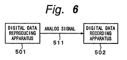
- Fig. 6 shows a schematic construction.
- Reference numeral 501 denotes a digital data reproducing apparatus; 502 a digital data recording apparatus; and 511 an analog signal transmitted between the apparatuses 501 and 502.
- the analog signal 511 which was D/A converted and outputted from the digital data reproducing apparatus 501 is inputted to the digital data recording apparatus 502 and is A/D converted and digitally recorded.
- the copy prevention control cannot be executed in the digital data recording apparatus 502.
- a few methods have been proposed as a method of preventing the copy by an analog interface.
- the analog signal is a video signal
- a phase of a color burst of an analog video signal to be outputted is partially inverted or a pseudo synchronization signal having an extremely large level is inserted as a sync signal for AGC, so that even if the normal reproduction can be performed.
- the video signal is recorded by the VTR, a normal reproduction image is not obtained in a monitor receiver.
- a digital copy prevention code is added to a signal in which an information source was digitally encoded.
- the digital recording apparatus detects the copy control signal and can execute the copy prevention control.
- the digital signal as a copy control signal added by the D/A conversion is dropped out.
- the copy control signal cannot be consequently detected in the digital recording apparatus in which the signal is finally recorded.
- the copy prevention control cannot be performed.
- it is necessary to prevent the copy by using the difference between the AGC methods of the VTR and the monitor receiver or the difference between the characteristics of the APC methods.
- the modified code signal can be combined with the audio signal to obtain a composite audio signal which is not readily distinguishable from the original audio signal by listening.
- the digital information can be recovered from the composite audio signal by a procedure which is essentially the compliment of that used to obtain the composite audio signal.
- EP-A-0,618,723 describes a system in which a video signal is processed to selectively permit copying by superposing in that portion of the video signal which does not contain useful picture information a copyright information signal indicative of whether the viewable picture that is displayed from the video signal is subject to copyright and a copy generation signal indicative of the number of successive generations of copies that can be made from the video signal.
- the copy control signal since a band of the additional information such as a copy control signal or the like is widened by the spread spectrum and the addition information is added to the signal band of the information source, the copy control signal cannot be deleted by a filter or the like. Since the spread spectrum signal is added, an influence by a deterioration or the like is hardly exerted on the original data. Further, as long as no synchronization is obtained at a timing when the spread spectrum is performed, it is difficult to perform not only the detection of the addition of the signal but also the detection of the copy control signal.
- different codes can be used as a PN code which is used for the spread spectrum and a several kinds of orthogonal codes can be also multiplied.
- the copy control signal is not erased even after the digital signal was D/A converted, the copy is prevented for the digital data recording apparatus which is connected in an analogwise manner. Since the copy control signal is not erased even in the signal recorded in the analog recording apparatus and the copy control signal cannot be deleted by a filter or the like, a very high effect of copy prevention can be obtained. Further, there is an advantage such that by multiplying the kind of spread spectrum and the orthogonal functions, an amount of information which can be added can be freely controlled.
- Fig. 7 is a diagram showing a construction of an embodiment of a recording apparatus according to the invention.
- an analog unit 800 has an information source 801 for generating an information signal to be recorded and a synthesizer 802 for synthesizing an information signal 831 and a copy control code 833.
- a synthesis signal 834 from the synthesizer 802 is converted into a digital signal by an ADC (analog/digital converter) 821.
- the digital signal is supplied to a digital unit 810.
- a copy control code generating unit 811 generates a copy control code 832 to control a copy prevention.
- the copy control code 832 is supplied to a spread spectrum unit 812 and is spread spectrum processed.
- the spread spectrum processed copy control code 833 is supplied to the synthesizer 802.
- a synthesis signal 835 which was converted into the digital signal is supplied to an encoding unit 813.
- the encoding unit 813 encodes digital information and its output 836 is supplied to a writing unit 814.
- a write signal 837 from the writing unit 814 is recorded into a recording medium 815.
- the analog unit 800 includes: a code reading unit 816 for extracting the spread spectrum processed copy control code multiplexed to the analog signal 831 from the information source 801; and a code changing unit 818 for changing the copy control code.
- the code changing unit 818 generates the synthesis signal 834 in which the copy control code which was spread spectrum processed was multiplexed to the analog information signal.
- the synthesis signal 834 is converted into the digital signal 835 by the ADC (analog/digital converter) 821.
- the digital signal 835 is supplied to the encoding unit 813 of the digital unit 810.
- An output signal of the ADC 821 is recorded into the recording medium 815 by the digital unit 810 in a manner similar to the foregoing embodiment.
- the information to be recorded there are audio information and/or video information.
- the recording medium 815 is a tape-shaped or disk-shaped medium in which a digital signal can be optically or magnetically recorded.
- a copy control code 838 extracted by the code reading unit 816 is supplied to a copy control signal control unit 817.
- the control unit 817 decodes the original copy control code and generates a copy control code 839 to be newly recorded.
- the copy control code 839 after the change is supplied to the code changing unit 818 and the copy control code in the synthesis signal 834 is changed.
- the new copy control code is also made identical to the original copy control code.
- the new copy control code is changed to a code indicative of the copy inhibition.
- the writing unit 814 When an original copy control signal 840 which is supplied from the copy control signal control unit 817 denotes the copy permission, the writing unit 814 records an output of the encoding unit 813 into the recording medium 815. When the signal 840 denotes the copy inhibition, the writing unit 814 doesn't record the output of the encoding unit 813 to the recording medium 815.
- the code reading unit 816 executes a process for an inverse spread spectrum and generates the copy control code 838 and also generates the synthesis signal and a control signal 841 for synchronization control to the code changing unit 818.
- the code changing unit 818 erases the original copy control code by the inverse spread spectrum and, subsequently, synthesizes the new copy control code 839 by the spread spectrum.
- the code changing unit 818 receives the control signal 841 which is used for the synchronization control that is executed for the inverse spread spectrum from the code reading unit 816.
- the copy control code is, for example, a code of two bits and is information to instruct a control about the copy as shown below.
- a reproducing apparatus 900 reproduces a recording medium 901 in which a synthesis signal has digitally been recorded.
- a read signal 931 outputted from the recording medium 901 for reproduction is set to a digital reproduction signal 932 by a reading unit 902 and is inputted to a decoding unit 903 and is decoded into a digital decoding signal 933 by the decoding unit 903. Further, the signal 933 is converted into an analog synthesis signal 934 by a DAC (digital/analog converter) 904.
- the analog synthesis signal 934 is supplied to an ADC 921 and an inverse spread spectrum unit 923 in a recording apparatus 920 through a communication path 911 of an analog interface 910. A copy control code which was spread spectrum processed has been added to the analog synthesis signal 934.
- a digital information signal 935 from the ADC 921 is encoded by an encoding unit 922.
- An encoding signal 936 from the encoding unit 922 is supplied to a writing unit 925.
- a write signal 939 from the writing unit 925 is recorded into a recording medium 926 for recording.
- a signal 937 which was inversely spread by the inverse spread spectrum unit 923 is inputted to a copy control code detecting unit 924 and a copy control code 938 is detected.
- the writing unit 925 is controlled by the copy control code 938. When the copy is permitted in accordance with the copy control code 938, the writing is performed. When the copy is inhibited, the writing is inhibited.
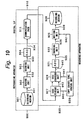
- Fig. 10 shows another embodiment of a copy system according to the invention.
- the reproducing apparatus 900 reproduces the recording medium 901, generates the analog synthesis signal 934 in which the analog information signal and the copy control code have been synthesized, and supplies the signal 934 to the recording apparatus 920 through the communication path 911 of the analog interface 910.
- the analog synthesis signal 934 is supplied to a code reading unit 927 of the recording apparatus 920 and a multiplexed copy control code 940 is extracted.
- a code changing unit 929 to change the copy control code is provided.
- the code changing unit 929 generates a synthesis signal 945 in which the spread spectrum processed copy control code has been multiplexed to the analog information signal.
- the synthesis signal 945 is converted into the digital signal 935 by the ADC 921.
- the digital signal is supplied to the encoding unit 922.
- the output signal of the ADC 921 is recorded into the recording medium 926 by the encoding unit 922.
- the copy control code 940 extracted by the code reading unit 927 is supplied to a copy control code control unit 928.
- the control unit 928 decodes the original copy control code 940 and generates a copy control code 941 to be newly recorded.
- the copy control code 941 after the change is supplied to the code changing unit 929 and the copy control code in the synthesis signal 945 is changed.
- the new copy control code is also made identical to the original copy control code.
- the original copy control code denotes the permission of the copy of one generation, the new copy control code is changed to the code indicative of the copy inhibition.
- the code reading unit 927 executes a process of the inverse spread spectrum, generates the copy control code 940, and also generates the synthesis signal and a control signal 943 which is used for synchronization control to the code changing unit 929.
- the code changing unit 929 erases the original control code by the inverse spread spectrum which was sync controlled by the control signal 943 and, subsequently, synthesizes the new copy control code 941 by the spread spectrum.
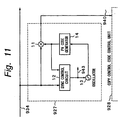
- Fig. 11 shows an example of the code reading unit 927 (similar to 816 as well).
- the synthesis signal 934 is supplied to a multiplier 11 and a sync control circuit 12.
- a PN (pseudo noise) code from a PN code generator 14 is supplied to the multiplier 11 and sync control circuit 12.
- the sync control circuit 12 extracts the timing signal 943 by using a fact that the PN code has a steep autocorrelation.
- An oscillating frequency and a phase of an oscillator 13 are controlled by the extracted timing signal 943 and an output signal of the oscillator 13 is supplied to the PN code generator 14.
- the PN code generated from the output of the oscillator 13 which was sync controlled and the synthesis signal 934 are multiplied by the multiplier 11, so that the demodulated copy control code 940 is derived from the multiplier 11.
- the copy control code 940 is supplied to the control unit 928.
- an M sequence maximum length sequence
- GOLD code or the like
- the former half sequence of its period and one bit on the lower significant side of the copy control code two bits
- the latter half sequence of the period and one bit on the higher significant side are multiplied and the modulation of the spread spectrum is executed.
- a way of modulating the copy control code by the spread spectrum is not limited to such an example but other various methods can be used.
- the spread spectrum modulation can be also performed.
- the invention is not limited to the direct modulation but the signal can be also modulated by a frequency hopping method or a time hopping method. Further, different PN codes can be also used for the spread spectrum and a few kinds of orthogonal codes can be also multiplied.
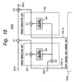
- Fig. 12 shows an example of the code changing unit 929 (similar to 818 as well).
- the synthesis signal 934 is supplied to a subtractor 31.
- a signal generated by a spread modulating unit 20 is supplied to the subtractor 31.
- the modulating unit 20 is constructed by a multiplier 21, an oscillator 23, and a PN code generator 24.
- the sync control signal 943 from the code reading unit 927 is supplied to the oscillator 23.
- An output of the oscillator 23 is supplied to the PN code generator 24 and the PN code in which a frequency and a phase are the same as those upon modulation is generated.
- Same information 941a as the copy control code extracted by the reading unit 927 is supplied from the control unit 928 to the multiplier 21. Therefore, by supplying an output of the multiplier 21 to the subtractor 31, the modulation copy control code included in the synthesis signal is erased.
- An output signal of the subtractor 31 is supplied to an adder 32.
- a signal generated by a spread modulating unit 40 is supplied to the adder 32.
- the modulating unit 40 is constructed by a multiplier 41 and a PN code generator 44.
- the output of the oscillator 23 of the modulating unit 20 is supplied to the PN code generator 44 and a PN code in which a frequency and a phase are the same as those upon modulation is generated.
- a copy control code 941b to be newly added is supplied from the control unit 928 to the multiplier 41. Therefore, by supplying an output of the multiplier 41 to the adder 32, the copy control code can be newly added.
- the copy control code is synthesized in an analogwise manner.
- information to be synthesized is not limited to the copy control code.
- the copyright management information is information that is necessary for a right management of the name of author, reversion of the right regarding a literary work, use conditions, identification number, and the like.
- the invention is not limited to the case of recording into the recording medium but can be also applied to a case of transmitting the analog information signal by a wire or a radio manner.
- addition information which was modulated by the spread spectrum can be also added to the analog information signal to be transmitted.
- the addition information is detected by the inverse spread spectrum and, on the basis of it, for example, the permission or inhibition of the reproduction of the analog information signal on the reception side is controlled.
- the copy control signal cannot be deleted by a filter or the like. So long as the synchronization cannot be obtained for the timing when the spread spectrum is performed, it is difficult to perform not only the detection of the copy control signal but also the detection of the addition of the signal. Therefore, according to the invention, the copy control can be certainly executed. According to the invention, since the spread spectrum processed signal is added, an influence by a deterioration or the like is hardly exerted on the original data. According to the invention as mentioned above, even after the digital signal was D/A converted, the copy control signal is not deleted.
- the copy can be prevented for the digital data recording apparatus which is connected in an analogwise manner and the copy control signal is also preserved even in the signal recorded in the analog recording apparatus.
Landscapes
- Engineering & Computer Science (AREA)
- Signal Processing (AREA)
- Computer Security & Cryptography (AREA)
- Multimedia (AREA)
- Signal Processing For Digital Recording And Reproducing (AREA)
- Television Signal Processing For Recording (AREA)
- Signal Processing Not Specific To The Method Of Recording And Reproducing (AREA)
- Television Systems (AREA)
- Two-Way Televisions, Distribution Of Moving Picture Or The Like (AREA)
- Management Or Editing Of Information On Record Carriers (AREA)
- Selective Calling Equipment (AREA)
- Indexing, Searching, Synchronizing, And The Amount Of Synchronization Travel Of Record Carriers (AREA)
Applications Claiming Priority (3)
| Application Number | Priority Date | Filing Date | Title |
|---|---|---|---|
| JP339959/95 | 1995-12-04 | ||
| JP33995995 | 1995-12-04 | ||
| JP33995995A JP3371187B2 (ja) | 1995-12-04 | 1995-12-04 | 情報信号記録装置および方法、並びに情報信号複製装置および方法 |
Publications (3)
| Publication Number | Publication Date |
|---|---|
| EP0778566A2 EP0778566A2 (en) | 1997-06-11 |
| EP0778566A3 EP0778566A3 (en) | 1997-12-17 |
| EP0778566B1 true EP0778566B1 (en) | 2003-03-26 |
Family
ID=18332390
Family Applications (1)
| Application Number | Title | Priority Date | Filing Date |
|---|---|---|---|
| EP96308568A Expired - Lifetime EP0778566B1 (en) | 1995-12-04 | 1996-11-27 | Apparatus and method for synthesising an information signal and a reproduction control signal and information signal recording apparatus |
Country Status (11)
| Country | Link |
|---|---|
| US (1) | US5982977A (ko) |
| EP (1) | EP0778566B1 (ko) |
| JP (1) | JP3371187B2 (ko) |
| KR (1) | KR100484208B1 (ko) |
| CN (1) | CN1161988C (ko) |
| AT (1) | ATE235735T1 (ko) |
| CA (1) | CA2191667C (ko) |
| DE (1) | DE69626936T2 (ko) |
| ES (1) | ES2192218T3 (ko) |
| ID (1) | ID17086A (ko) |
| TW (1) | TW353174B (ko) |
Cited By (1)
| Publication number | Priority date | Publication date | Assignee | Title |
|---|---|---|---|---|
| US8248506B2 (en) | 1998-07-17 | 2012-08-21 | Sony Corporation | Imaging apparatus |
Families Citing this family (57)
| Publication number | Priority date | Publication date | Assignee | Title |
|---|---|---|---|---|
| US6944298B1 (en) | 1993-11-18 | 2005-09-13 | Digimare Corporation | Steganographic encoding and decoding of auxiliary codes in media signals |
| US6983051B1 (en) | 1993-11-18 | 2006-01-03 | Digimarc Corporation | Methods for audio watermarking and decoding |
| US6611607B1 (en) | 1993-11-18 | 2003-08-26 | Digimarc Corporation | Integrating digital watermarks in multimedia content |
| US5748763A (en) | 1993-11-18 | 1998-05-05 | Digimarc Corporation | Image steganography system featuring perceptually adaptive and globally scalable signal embedding |
| US6614914B1 (en) | 1995-05-08 | 2003-09-02 | Digimarc Corporation | Watermark embedder and reader |
| JP3528394B2 (ja) * | 1996-01-23 | 2004-05-17 | ソニー株式会社 | データ記録再生装置 |
| JP3695016B2 (ja) * | 1996-10-15 | 2005-09-14 | ソニー株式会社 | ビデオ信号処理装置及びビデオ信号処理方法 |
| JP3778236B2 (ja) * | 1996-10-22 | 2006-05-24 | ソニー株式会社 | 映像信号伝送方法、映像信号出力方法、映像信号出力装置および付加情報検出装置 |
| JP3707165B2 (ja) * | 1996-11-01 | 2005-10-19 | ソニー株式会社 | 映像伝送方法、映像処理方法、映像伝送装置および映像処理装置 |
| JP3736588B2 (ja) * | 1996-11-18 | 2006-01-18 | ソニー株式会社 | 情報出力装置、情報出力方法、記録装置および情報複製防止制御方法 |
| JPH10172235A (ja) * | 1996-12-09 | 1998-06-26 | Sony Corp | 情報記録更新方法、情報記録更新装置、記録媒体初期化装置および記録媒体 |
| JPH10174063A (ja) * | 1996-12-10 | 1998-06-26 | Sony Corp | 映像信号伝送方法、重畳情報抽出方法、映像信号出力装置、映像信号受信装置および映像信号記録媒体 |
| TW401702B (en) * | 1997-01-20 | 2000-08-11 | Sony Corp | Image signal transmitting method, superimposed signal extracting method, image signal output apparatus, image signal receiving apparatus and image signal recording medium |
| JP3867738B2 (ja) * | 1997-01-22 | 2007-01-10 | ソニー株式会社 | 映像信号伝送方法および重畳情報抽出方法 |
| JP3901268B2 (ja) * | 1997-01-23 | 2007-04-04 | ソニー株式会社 | 情報信号出力制御装置、情報信号出力制御方法、情報信号複製防止装置および情報信号複製防止方法 |
| KR100238082B1 (ko) * | 1997-04-14 | 2000-01-15 | 윤종용 | 복사모드를 자동으로 선택하는 복사장치 |
| JPH1145548A (ja) * | 1997-05-29 | 1999-02-16 | Sony Corp | オーディオデータの記録方法、記録装置、伝送方法 |
| JPH1145556A (ja) * | 1997-05-29 | 1999-02-16 | Sony Corp | オーディオデータの記録装置及びオーディオデータの記録方法 |
| JPH10336578A (ja) | 1997-06-05 | 1998-12-18 | Sony Corp | 映像信号への情報付加方法、付加情報検出方法および装置 |
| JPH10340531A (ja) * | 1997-06-10 | 1998-12-22 | Sony Corp | 情報信号記録装置、情報信号記録方法および情報信号記録媒体 |
| US6356704B1 (en) | 1997-06-16 | 2002-03-12 | Ati Technologies, Inc. | Method and apparatus for detecting protection of audio and video signals |
| EP0886274A3 (en) * | 1997-06-17 | 1999-09-08 | Sony Corporation | Information signal processing unit |
| US6430356B1 (en) * | 1997-06-27 | 2002-08-06 | Victor Company Of Japan, Ltd. | Information recording and reproducing apparatus for dubbing an audio-visual digital signal and auxiliary information recorded in a magnetic tape |
| JP4045381B2 (ja) * | 1997-08-29 | 2008-02-13 | ソニー株式会社 | 映像信号への付加情報の重畳方法および装置 |
| JPH1175165A (ja) | 1997-08-29 | 1999-03-16 | Sony Corp | スペクトラム拡散信号の検出方法および検出装置 |
| JPH1173725A (ja) | 1997-08-29 | 1999-03-16 | Sony Corp | 情報信号記録再生システム、情報記録装置、情報信号再生装置および情報信号記録再生方法 |
| JPH1175166A (ja) * | 1997-08-29 | 1999-03-16 | Sony Corp | 映像信号への付加情報の重畳方法および重畳装置 |
| JP4456185B2 (ja) * | 1997-08-29 | 2010-04-28 | 富士通株式会社 | コピー防止機能を持つ見える透かし入り動画像記録媒体とその作成・検出および録画・再生装置 |
| JP4003096B2 (ja) | 1997-09-01 | 2007-11-07 | ソニー株式会社 | 映像信号への付加情報の重畳方法および重畳装置 |
| TW398116B (en) * | 1997-09-01 | 2000-07-11 | Sony Corp | Method and apparatus for detecting spectrum spread signals |
| JP3867744B2 (ja) * | 1997-09-01 | 2007-01-10 | ソニー株式会社 | スペクトラム拡散信号検出方法および装置 |
| JP3750707B2 (ja) * | 1997-09-02 | 2006-03-01 | ソニー株式会社 | スペクトラム拡散信号検出方法および装置 |
| JP3775016B2 (ja) * | 1997-09-02 | 2006-05-17 | ソニー株式会社 | 送信及び/又は記録装置、受信及び/又は再生装置、送受信/記録再生装置、送受信システム、送信及び/又は記録方法、受信及び/又は再生方法、伝送方法、並びに、記録媒体 |
| JPH1188848A (ja) | 1997-09-02 | 1999-03-30 | Sony Corp | 付加情報重畳伝送方法、付加情報重畳伝送システム、付加情報重畳装置および付加情報検出装置並びに記録媒体 |
| JP4003098B2 (ja) | 1997-09-17 | 2007-11-07 | ソニー株式会社 | 画像信号への情報付加方法および情報付加装置 |
| JP3956479B2 (ja) | 1998-04-27 | 2007-08-08 | ソニー株式会社 | 移動通信システム、移動局及び基地局 |
| JPH11328851A (ja) * | 1998-05-19 | 1999-11-30 | Sony Corp | 端末装置及び再生方法 |
| JP2000013585A (ja) * | 1998-06-19 | 2000-01-14 | Sony Corp | 付加情報の重畳装置、付加情報の重畳方法、画像情報記録装置および画像情報記録方法 |
| US6976265B1 (en) * | 1998-10-08 | 2005-12-13 | Ati International Srl | Method and apparatus for controlling display of content signals |
| TW484267B (en) | 1998-11-05 | 2002-04-21 | Sony Corp | Additional information transmission method, additional information transmission system, information signal output apparatus, information signal processing apparatus information signal recording apparatus and information signal recording medium |
| JP3868643B2 (ja) | 1998-12-03 | 2007-01-17 | 株式会社日立製作所 | デジタル情報複製制限方法、デジタル情報複製制限装置およびデジタル情報記録装置 |
| EP1014361B1 (en) | 1998-12-11 | 2006-08-09 | Sony Corporation | Technique for controlling copying of data |
| US20070100757A1 (en) | 1999-05-19 | 2007-05-03 | Rhoads Geoffrey B | Content Protection Arrangements |
| US6690880B1 (en) * | 1999-05-21 | 2004-02-10 | Ati International, Srl | Method and apparatus for copy protection detection in a video signal |
| JP2001067792A (ja) | 1999-08-30 | 2001-03-16 | Sony Corp | 記録装置および方法、並びに記録媒体 |
| JP3728621B2 (ja) * | 2000-02-10 | 2005-12-21 | 松下電器産業株式会社 | デジタルデータのコピー制御方法及び再生装置 |
| US6845170B2 (en) | 2001-01-11 | 2005-01-18 | Sony Corporation | Watermark resistant to resizing and rotation |
| JP4512280B2 (ja) * | 2001-02-16 | 2010-07-28 | 日立コンシューマエレクトロニクス株式会社 | ストリームデータ再生装置 |
| US6865273B2 (en) | 2002-06-05 | 2005-03-08 | Sony Corporation | Method and apparatus to detect watermark that are resistant to resizing, rotation and translation |
| US7602936B2 (en) | 2001-03-08 | 2009-10-13 | Sony Corporation | Method to make wavelet watermarks resistant to affine transformations |
| US8122465B2 (en) * | 2001-07-05 | 2012-02-21 | Digimarc Corporation | Watermarking to set video usage permissions |
| US7263202B2 (en) | 2001-07-05 | 2007-08-28 | Digimarc Corporation | Watermarking to control video recording |
| KR20050042037A (ko) * | 2001-11-01 | 2005-05-04 | 매텔 인코포레이티드 | 디지털 오디오 장치 |
| US7433489B2 (en) | 2001-11-28 | 2008-10-07 | Sony Electronics Inc. | Method to ensure temporal synchronization and reduce complexity in the detection of temporal watermarks |
| US7317811B2 (en) | 2001-11-28 | 2008-01-08 | Sony Electronics Inc. | Method to decode temporal watermarks in compressed video |
| JP2003186500A (ja) * | 2001-12-17 | 2003-07-04 | Sony Corp | 情報伝達システム、情報符号化装置および情報復号装置 |
| US8929011B1 (en) * | 2013-10-14 | 2015-01-06 | Lsi Corporation | Sync mark system for two dimensional magnetic recording |
Family Cites Families (13)
| Publication number | Priority date | Publication date | Assignee | Title |
|---|---|---|---|---|
| GB1572622A (en) * | 1977-03-29 | 1980-07-30 | Secr Defence | Code synchronising apparatus |
| JPH0731877B2 (ja) * | 1985-07-03 | 1995-04-10 | 株式会社日立製作所 | 情報記録再生方法及び装置 |
| KR930008167B1 (ko) * | 1986-08-11 | 1993-08-26 | 매크로비젼 코포레이션 | 비데오 레코더의 비데오 디스에이블링 회로를 이용하여 비데오 프로그램의 복사를 방지하는 방법 및 장치 |
| DE3851724T2 (de) * | 1987-07-08 | 1995-05-04 | Matsushita Electric Ind Co Ltd | Verfahren und Gerät zum Schutz von Kopiersignalen. |
| JP2845915B2 (ja) * | 1989-01-06 | 1999-01-13 | 株式会社日立製作所 | 情報再生方法および情報再生装置 |
| US5134496A (en) * | 1989-05-26 | 1992-07-28 | Technicolor Videocassette Of Michigan Inc. | Bilateral anti-copying device for video systems |
| JP3114263B2 (ja) * | 1991-07-29 | 2000-12-04 | ソニー株式会社 | 映像信号記録システム |
| US5319735A (en) * | 1991-12-17 | 1994-06-07 | Bolt Beranek And Newman Inc. | Embedded signalling |
| JP3049155B2 (ja) * | 1992-06-15 | 2000-06-05 | 株式会社リコー | 光ディスク再生方法及びその装置 |
| JP2618571B2 (ja) * | 1992-09-24 | 1997-06-11 | 富士通株式会社 | 光磁気ディスクのデータ再生回路 |
| US5315448A (en) * | 1993-03-18 | 1994-05-24 | Macrovision Corporation | Copy protection for hybrid digital video tape recording and unprotected source material |
| JP3250333B2 (ja) * | 1993-04-02 | 2002-01-28 | ソニー株式会社 | 映像信号処理方法、映像信号記録方法、映像信号再生方法、映像信号処理装置、映像信号記録装置及び映像信号再生装置 |
| JP3321972B2 (ja) * | 1994-02-15 | 2002-09-09 | ソニー株式会社 | ディジタル信号記録装置 |
-
1995
- 1995-12-04 JP JP33995995A patent/JP3371187B2/ja not_active Expired - Fee Related
-
1996
- 1996-11-22 US US08/755,101 patent/US5982977A/en not_active Expired - Lifetime
- 1996-11-27 ES ES96308568T patent/ES2192218T3/es not_active Expired - Lifetime
- 1996-11-27 AT AT96308568T patent/ATE235735T1/de active
- 1996-11-27 DE DE69626936T patent/DE69626936T2/de not_active Expired - Lifetime
- 1996-11-27 EP EP96308568A patent/EP0778566B1/en not_active Expired - Lifetime
- 1996-11-29 TW TW085114759A patent/TW353174B/zh not_active IP Right Cessation
- 1996-11-29 CA CA002191667A patent/CA2191667C/en not_active Expired - Fee Related
- 1996-12-02 ID IDP963567A patent/ID17086A/id unknown
- 1996-12-02 KR KR1019960061085A patent/KR100484208B1/ko not_active IP Right Cessation
- 1996-12-04 CN CNB961233915A patent/CN1161988C/zh not_active Expired - Fee Related
Cited By (3)
| Publication number | Priority date | Publication date | Assignee | Title |
|---|---|---|---|---|
| US8248506B2 (en) | 1998-07-17 | 2012-08-21 | Sony Corporation | Imaging apparatus |
| US8830355B2 (en) | 1998-07-17 | 2014-09-09 | Sony Corporation | Imaging apparatus |
| US9210340B2 (en) | 1998-07-17 | 2015-12-08 | Sony Corporation | Imaging apparatus |
Also Published As
| Publication number | Publication date |
|---|---|
| ATE235735T1 (de) | 2003-04-15 |
| EP0778566A2 (en) | 1997-06-11 |
| EP0778566A3 (en) | 1997-12-17 |
| KR100484208B1 (ko) | 2005-08-17 |
| JPH09163341A (ja) | 1997-06-20 |
| TW353174B (en) | 1999-02-21 |
| CN1161988C (zh) | 2004-08-11 |
| CA2191667C (en) | 2005-07-12 |
| ES2192218T3 (es) | 2003-10-01 |
| ID17086A (id) | 1997-12-04 |
| US5982977A (en) | 1999-11-09 |
| CA2191667A1 (en) | 1997-06-05 |
| DE69626936T2 (de) | 2004-02-05 |
| KR970050856A (ko) | 1997-07-29 |
| CN1161620A (zh) | 1997-10-08 |
| JP3371187B2 (ja) | 2003-01-27 |
| DE69626936D1 (de) | 2003-04-30 |
Similar Documents
| Publication | Publication Date | Title |
|---|---|---|
| EP0778566B1 (en) | Apparatus and method for synthesising an information signal and a reproduction control signal and information signal recording apparatus | |
| CN1127851C (zh) | 信息输出设备、记录设备和复制控制系统 | |
| US6282654B1 (en) | Information signal recording/reproducing system, information signal recording device, information signal reproducing device and information signal recording/reproducing process | |
| US20020150246A1 (en) | Additional information embedding device and additional information embedding method | |
| EP1032205B1 (en) | Additional information embedding and detecting method and apparatus | |
| KR100829177B1 (ko) | 콘텐츠 데이터, 기록매체, 기록방법, 기록장치, 재생방법 및 재생장치 | |
| US6526510B1 (en) | Signal reproducing method and apparatus, signal recording method and apparatus and signal recording system | |
| KR20000006035A (ko) | 복제세대관리방법,정보신호재생방법,정보신호재생장치및정보신호기록장치 | |
| KR20000035263A (ko) | 부가 정보 전송 방법, 부가 정보 전송 시스템, 정보 신호출력 장치, 정보 신호 처리 장치, 정보 신호 기록 장치 및정보 신호 기록 매체 | |
| KR20000052380A (ko) | 정보 신호 저작권 보호 방법, 정보 신호 기록 방법과장치, 및 정보 신호 출력 방법과 장치 | |
| JPH10200504A (ja) | 情報信号伝送方法、複製防止制御方法、情報信号出力装置、情報信号記録装置および情報信号記録媒体 | |
| US6381262B1 (en) | Information signal processing unit | |
| US20010007608A1 (en) | Information transmission method, information duplication prohibiting method, information duplication prohibiting device and information crevording medium | |
| US6782191B1 (en) | Additional information superposing method, information signal copy control method, information signal output device and information signal recording device | |
| JP3867738B2 (ja) | 映像信号伝送方法および重畳情報抽出方法 | |
| KR970071714A (ko) | 주신호에 중첩되어 기록된 복제방지신호를 가지는 기록매체와, 상기 기록매체를 재생하는 장치와, 상기 기록매체에 복제방지신호를 기록하는 장치와, 상기 중첩된 복제방지신호를 가지는 디지털신호를 송신하는 장치 | |
| US20010053279A1 (en) | Video signal transmission method, superimposed information extraction method, video signal output device, video signal receiving device, and video recording medium | |
| KR100693455B1 (ko) | 스펙트럼 확산신호 검출방법 및 장치 | |
| KR100717251B1 (ko) | 스테레오 신호와 데이터 신호를 보유한 기록매체 | |
| US6427047B1 (en) | Apparatus and method for protecting the unauthorized duplication of a signal | |
| MXPA96006067A (en) | Apparatus and method for synthesizing information signs and reproduction control signals, and apparatus for recording information signals | |
| US6359905B1 (en) | Method and apparatus of detecting spectrum spread signal | |
| JP3888401B2 (ja) | 情報信号出力装置、情報信号出力方法、情報信号再生装置および情報信号再生方法 | |
| JPH0746535A (ja) | デジタル信号記録装置、デジタル信号再生装置 | |
| JPH10334593A (ja) | 情報信号記録制御方法、情報信号処理装置および情報信号記録媒体 |
Legal Events
| Date | Code | Title | Description |
|---|---|---|---|
| PUAI | Public reference made under article 153(3) epc to a published international application that has entered the european phase |
Free format text: ORIGINAL CODE: 0009012 |
|
| AK | Designated contracting states |
Kind code of ref document: A2 Designated state(s): AT DE ES FR GB IT NL |
|
| PUAL | Search report despatched |
Free format text: ORIGINAL CODE: 0009013 |
|
| AK | Designated contracting states |
Kind code of ref document: A3 Designated state(s): AT DE ES FR GB IT NL |
|
| 17P | Request for examination filed |
Effective date: 19980514 |
|
| 17Q | First examination report despatched |
Effective date: 20000629 |
|
| GRAH | Despatch of communication of intention to grant a patent |
Free format text: ORIGINAL CODE: EPIDOS IGRA |
|
| RTI1 | Title (correction) |
Free format text: APPARATUS AND METHOD FOR SYNTHESISING AN INFORMATION SIGNAL AND A REPRODUCTION CONTROL SIGNAL AND INFORMATION SIGNAL RECORDING APPARATUS |
|
| GRAH | Despatch of communication of intention to grant a patent |
Free format text: ORIGINAL CODE: EPIDOS IGRA |
|
| GRAA | (expected) grant |
Free format text: ORIGINAL CODE: 0009210 |
|
| AK | Designated contracting states |
Designated state(s): AT DE ES FR GB IT NL |
|
| REG | Reference to a national code |
Ref country code: GB Ref legal event code: FG4D |
|
| REF | Corresponds to: |
Ref document number: 69626936 Country of ref document: DE Date of ref document: 20030430 Kind code of ref document: P |
|
| REG | Reference to a national code |
Ref country code: ES Ref legal event code: FG2A Ref document number: 2192218 Country of ref document: ES Kind code of ref document: T3 |
|
| ET | Fr: translation filed | ||
| PLBE | No opposition filed within time limit |
Free format text: ORIGINAL CODE: 0009261 |
|
| STAA | Information on the status of an ep patent application or granted ep patent |
Free format text: STATUS: NO OPPOSITION FILED WITHIN TIME LIMIT |
|
| 26N | No opposition filed |
Effective date: 20031230 |
|
| REG | Reference to a national code |
Ref country code: GB Ref legal event code: 746 Effective date: 20091130 |
|
| PGFP | Annual fee paid to national office [announced via postgrant information from national office to epo] |
Ref country code: AT Payment date: 20101112 Year of fee payment: 15 |
|
| PGFP | Annual fee paid to national office [announced via postgrant information from national office to epo] |
Ref country code: DE Payment date: 20101119 Year of fee payment: 15 |
|
| PGFP | Annual fee paid to national office [announced via postgrant information from national office to epo] |
Ref country code: GB Payment date: 20101118 Year of fee payment: 15 Ref country code: IT Payment date: 20101126 Year of fee payment: 15 |
|
| PGFP | Annual fee paid to national office [announced via postgrant information from national office to epo] |
Ref country code: FR Payment date: 20111130 Year of fee payment: 16 Ref country code: NL Payment date: 20111124 Year of fee payment: 16 Ref country code: ES Payment date: 20111115 Year of fee payment: 16 |
|
| REG | Reference to a national code |
Ref country code: NL Ref legal event code: V1 Effective date: 20130601 |
|
| REG | Reference to a national code |
Ref country code: AT Ref legal event code: MM01 Ref document number: 235735 Country of ref document: AT Kind code of ref document: T Effective date: 20121127 |
|
| GBPC | Gb: european patent ceased through non-payment of renewal fee |
Effective date: 20121127 |
|
| PG25 | Lapsed in a contracting state [announced via postgrant information from national office to epo] |
Ref country code: AT Free format text: LAPSE BECAUSE OF NON-PAYMENT OF DUE FEES Effective date: 20121127 |
|
| REG | Reference to a national code |
Ref country code: FR Ref legal event code: ST Effective date: 20130731 |
|
| PG25 | Lapsed in a contracting state [announced via postgrant information from national office to epo] |
Ref country code: IT Free format text: LAPSE BECAUSE OF NON-PAYMENT OF DUE FEES Effective date: 20121127 Ref country code: NL Free format text: LAPSE BECAUSE OF NON-PAYMENT OF DUE FEES Effective date: 20130601 |
|
| REG | Reference to a national code |
Ref country code: DE Ref legal event code: R119 Ref document number: 69626936 Country of ref document: DE Effective date: 20130601 |
|
| PG25 | Lapsed in a contracting state [announced via postgrant information from national office to epo] |
Ref country code: DE Free format text: LAPSE BECAUSE OF NON-PAYMENT OF DUE FEES Effective date: 20130601 |
|
| PG25 | Lapsed in a contracting state [announced via postgrant information from national office to epo] |
Ref country code: GB Free format text: LAPSE BECAUSE OF NON-PAYMENT OF DUE FEES Effective date: 20121127 Ref country code: FR Free format text: LAPSE BECAUSE OF NON-PAYMENT OF DUE FEES Effective date: 20121130 |
|
| REG | Reference to a national code |
Ref country code: ES Ref legal event code: FD2A Effective date: 20140305 |
|
| PG25 | Lapsed in a contracting state [announced via postgrant information from national office to epo] |
Ref country code: ES Free format text: LAPSE BECAUSE OF NON-PAYMENT OF DUE FEES Effective date: 20121128 |