EP0778088A2 - Verfahren und Vorrichtung zum Formen einer Beschichtung in einem Rohr - Google Patents
Verfahren und Vorrichtung zum Formen einer Beschichtung in einem Rohr Download PDFInfo
- Publication number
- EP0778088A2 EP0778088A2 EP96250280A EP96250280A EP0778088A2 EP 0778088 A2 EP0778088 A2 EP 0778088A2 EP 96250280 A EP96250280 A EP 96250280A EP 96250280 A EP96250280 A EP 96250280A EP 0778088 A2 EP0778088 A2 EP 0778088A2
- Authority
- EP
- European Patent Office
- Prior art keywords
- pipe
- powder material
- resin powder
- temperature
- fluorine resin
- Prior art date
- Legal status (The legal status is an assumption and is not a legal conclusion. Google has not performed a legal analysis and makes no representation as to the accuracy of the status listed.)
- Withdrawn
Links
Images


Classifications
-
- B—PERFORMING OPERATIONS; TRANSPORTING
- B05—SPRAYING OR ATOMISING IN GENERAL; APPLYING FLUENT MATERIALS TO SURFACES, IN GENERAL
- B05D—PROCESSES FOR APPLYING FLUENT MATERIALS TO SURFACES, IN GENERAL
- B05D1/00—Processes for applying liquids or other fluent materials
- B05D1/002—Processes for applying liquids or other fluent materials the substrate being rotated
-
- B—PERFORMING OPERATIONS; TRANSPORTING
- B05—SPRAYING OR ATOMISING IN GENERAL; APPLYING FLUENT MATERIALS TO SURFACES, IN GENERAL
- B05D—PROCESSES FOR APPLYING FLUENT MATERIALS TO SURFACES, IN GENERAL
- B05D7/00—Processes, other than flocking, specially adapted for applying liquids or other fluent materials to particular surfaces or for applying particular liquids or other fluent materials
- B05D7/22—Processes, other than flocking, specially adapted for applying liquids or other fluent materials to particular surfaces or for applying particular liquids or other fluent materials to internal surfaces, e.g. of tubes
- B05D7/222—Processes, other than flocking, specially adapted for applying liquids or other fluent materials to particular surfaces or for applying particular liquids or other fluent materials to internal surfaces, e.g. of tubes of pipes
-
- B—PERFORMING OPERATIONS; TRANSPORTING
- B29—WORKING OF PLASTICS; WORKING OF SUBSTANCES IN A PLASTIC STATE IN GENERAL
- B29C—SHAPING OR JOINING OF PLASTICS; SHAPING OF MATERIAL IN A PLASTIC STATE, NOT OTHERWISE PROVIDED FOR; AFTER-TREATMENT OF THE SHAPED PRODUCTS, e.g. REPAIRING
- B29C41/00—Shaping by coating a mould, core or other substrate, i.e. by depositing material and stripping-off the shaped article; Apparatus therefor
- B29C41/02—Shaping by coating a mould, core or other substrate, i.e. by depositing material and stripping-off the shaped article; Apparatus therefor for making articles of definite length, i.e. discrete articles
- B29C41/04—Rotational or centrifugal casting, i.e. coating the inside of a mould by rotating the mould
-
- B—PERFORMING OPERATIONS; TRANSPORTING
- B29—WORKING OF PLASTICS; WORKING OF SUBSTANCES IN A PLASTIC STATE IN GENERAL
- B29C—SHAPING OR JOINING OF PLASTICS; SHAPING OF MATERIAL IN A PLASTIC STATE, NOT OTHERWISE PROVIDED FOR; AFTER-TREATMENT OF THE SHAPED PRODUCTS, e.g. REPAIRING
- B29C41/00—Shaping by coating a mould, core or other substrate, i.e. by depositing material and stripping-off the shaped article; Apparatus therefor
- B29C41/02—Shaping by coating a mould, core or other substrate, i.e. by depositing material and stripping-off the shaped article; Apparatus therefor for making articles of definite length, i.e. discrete articles
- B29C41/20—Shaping by coating a mould, core or other substrate, i.e. by depositing material and stripping-off the shaped article; Apparatus therefor for making articles of definite length, i.e. discrete articles incorporating preformed parts or layers, e.g. moulding inserts or for coating articles
-
- B—PERFORMING OPERATIONS; TRANSPORTING
- B29—WORKING OF PLASTICS; WORKING OF SUBSTANCES IN A PLASTIC STATE IN GENERAL
- B29C—SHAPING OR JOINING OF PLASTICS; SHAPING OF MATERIAL IN A PLASTIC STATE, NOT OTHERWISE PROVIDED FOR; AFTER-TREATMENT OF THE SHAPED PRODUCTS, e.g. REPAIRING
- B29C41/00—Shaping by coating a mould, core or other substrate, i.e. by depositing material and stripping-off the shaped article; Apparatus therefor
- B29C41/34—Component parts, details or accessories; Auxiliary operations
- B29C41/46—Heating or cooling
-
- B—PERFORMING OPERATIONS; TRANSPORTING
- B29—WORKING OF PLASTICS; WORKING OF SUBSTANCES IN A PLASTIC STATE IN GENERAL
- B29C—SHAPING OR JOINING OF PLASTICS; SHAPING OF MATERIAL IN A PLASTIC STATE, NOT OTHERWISE PROVIDED FOR; AFTER-TREATMENT OF THE SHAPED PRODUCTS, e.g. REPAIRING
- B29C41/00—Shaping by coating a mould, core or other substrate, i.e. by depositing material and stripping-off the shaped article; Apparatus therefor
- B29C41/34—Component parts, details or accessories; Auxiliary operations
- B29C41/52—Measuring, controlling or regulating
-
- F—MECHANICAL ENGINEERING; LIGHTING; HEATING; WEAPONS; BLASTING
- F16—ENGINEERING ELEMENTS AND UNITS; GENERAL MEASURES FOR PRODUCING AND MAINTAINING EFFECTIVE FUNCTIONING OF MACHINES OR INSTALLATIONS; THERMAL INSULATION IN GENERAL
- F16L—PIPES; JOINTS OR FITTINGS FOR PIPES; SUPPORTS FOR PIPES, CABLES OR PROTECTIVE TUBING; MEANS FOR THERMAL INSULATION IN GENERAL
- F16L57/00—Protection of pipes or objects of similar shape against external or internal damage or wear
Definitions
- the present invention relates to a method and apparatus for molding a lining in a pipe, in which the lining is formed on the inner face of the pipe.
- a lining made of a fluorine resin is sometimes formed on the inner circumferential face of a pipe used as a duct for flowing, e.g., a pulp slurry or a plaster slurry, so as to increase corrosion resistance and wear resistance of the pipe and to make attachment of foreign matters difficult.
- injection molding is generally used wherein the pipe is set in a die, and thereafter a molten fluorine resin is forced with a pressure into a space where a lining is to be formed.
- a core partly constituting the die may be corroded by the fluorine resin, and after the lining is formed, the core must be extracted.
- rotational molding is also employed with which molding is performed without using a die and without pressurizing the resin, thereby uniforming the molding quality.
- a powdery hot-meltable fluorine resin material is sealed in a horizontal pipe, and thereafter this pipe is heated and rotated about its axis as the center.
- the heating temperature is set to a temperature higher than the foaming temperature of the fluorine resin material.
- the rotation speed during rotation is set to a speed at which the fluorine resin material gathers at the lower portion in the pipe by its own weight when the fluorine resin material is not melted.
- the powdery fluorine resin material is repeatedly sprinkled on the face of the melt layer.
- the melt layer increases (grows).
- heating of the lining body is stopped, and the molten fluorine resin is cooled to solidify, thereby forming a uniform lining on the inner circumferential face of the pipe.
- This rotational molding is suitable also for forming a lining on the inner circumferential face of the measurement pipe of an electromagnetic flowmeter interposed in the duct described above.
- the fluorine resin material is heated to a temperature higher than the foaming temperature, the fluorine resin itself is decomposed to form bubbles in the molten portion. When these bubbles are broken on the face of the molten portion, the face of the molten portion becomes rough.
- the powdery fluorine resin material is deposited on the face of the melt layer, a fluorine resin material which is not melted or is not melted completely remains on the face of the molten portion at the end of heating to roughen the face of the molten portion.
- the face of the molten portion becomes rough in this manner, the face of the lining becomes satin-like.
- the face of the lining is satin-like, when, e.g., a pulp slurry or plaster slurry is flowed on this face, the solid particles of such a slurry tend to attach to the face of the lining easily.
- the solid particles attach to the face of the lining, extra solid particles attach to the attached solid particles and are deposited. Then, the deposited solid particles grow to narrow the duct, thus increasing the flow resistance.
- the sectional area of the duct i.e., the inner diameter of the duct changes to degrade the measurement precision.
- the inner circumferential face of the line is satin-like, not only the solid particles attach to it, but also the resistance against the flow of the pulp slurry or plaster slurry along the inner circumferential face of the lining increases, thus wearing the lining easily.
- the pipe directly comes into contact with the slurry and is thus corroded.
- dielectric breakdown tends to occur between the electrode and ground.
- a method is proposed as disclosed in, e.g., Japanese Patent Laid-Open No. 4-220524, wherein a cylindrical columnar core is mounted in the axial portion of the pipe, and a molten fluorine resin material is injected between the pipe and the core, thereby forming a lining. More specifically, if the outer circumferential face of the core is formed to have a mirror face, the shape of the outer circumferential face of the core is transferred to the inner circumferential face of the lining, thereby making the inner circumferential face of the lining to have a mirror face.
- a method of molding a lining in a pipe comprising the steps of sealing a hot-meltable resin powder material in the pipe, uniformly diffusing the resin powder material on an entire inner circumferential face of the pipe by rotating the pipe, urging the resin powder material against the inner circumferential face of the pipe by increasing a rotation speed of the pipe up to a predetermined rotation speed, melting the resin powder material urged against the inner circumferential face of the pipe by heating the pipe to a predetermined temperature not less than the melting temperature of the resin powder material and less than the foaming temperature of the resin powder material, and after the resin powder material is entirely melted, cooling the resin powder material while rotating the pipe, thereby forming the lining having a predetermined thickness on the inner circumferential face of the pipe.
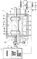
- Fig. 1 shows a lining molding apparatus according to an embodiment of the present invention.
- a lining molding apparatus 1 is constituted by a heat-insulated furnace 2 connected to a rotating unit, a heating unit, and a cooling unit (to be described later), and a controller 3 for controlling the rotating unit, the heating unit, and the cooling unit.
- the heat-insulated furnace 2 has such a structure that heat in it will not be easily transferred to the outside.
- An electromagnetic flowmeter measurement tube 4 which is rotatably held by main shafts 5 and 6 is accommodated in the heat-insulated furnace 2.
- the measurement tube 4 has opening portions at its two ends and is formed into a stainless steel cylinder.
- the main shafts 5 and 6 respectively have a pair of holders 8a and 8b each having one end for holding a corresponding one of the two end portions of the measurement tube 4 in the heat-insulated furnace 2, and are rotatably supported to extend through a pair of opposing side walls 2a and 2b of the heat-insulated furnace 2.
- the axes of the main shafts 5 and 6 coincide with each other to form one axis.
- Main shaft bearing members 7 are provided on the outer faces of the side walls 2a and 2b of the heat-insulated furnace 2.
- the holders 8a and 8b When the holders 8a and 8b engage with the end portions of the measurement tube 4, they close the opening portions of the measurement tube 4 and rotate together with the main shafts 5 and 6.
- the holders 8a and 8b become movable in the axial direction with respect to the main shafts 5 and 6 when a lock mechanism (to be described later) is unlocked. More specifically, when the holders 8a and 8b are moved in the axial direction with respect to the main shafts 5 and 6 to increase the interval between the holders 8a and 8b, the measurement tube 4 can be removed from the holders 8a and 8b. To mount the measurement tube 4, the interval between the holders 8a and 8b is decreased to clamp the measurement tube 4, thereby fixing the measurement tube 4 with the main shafts 5 and 6.
- a preset amount of powdery hot-meltable fluorine resin material 9 is filled in the measurement tube 4 in advance, as shown in Fig. 3A.
- the measurement tube 4 accommodating the fluorine resin material 9 is held by the holders 8a and 8b and is sealed, the fluorine resin material 9 is sealed in the measurement tube 4.
- a reinforcing punching plate or the like is mounted and welded on the inner circumferential portion of the electromagnetic flowmeter measurement tube 4, but is not illustrated in Figs. 3A to 3D.
- a measurement pipe loading/unloading port (not shown) having a door is mounted on the heat-insulated furnace 2. The measurement tube 4 is loaded in or unloaded from the heat-insulated furnace 2 through this measurement pipe loading/unloading port having the door.
- the main shaft 5 is coupled to a motor 11 through a belt-type transmission mechanism 10 at an end portion opposite to the holder 8a.
- the motor 11 has an ability of rotating the measurement tube 4 at such a rotation speed that the fluorine resin material 9 sealed in the measurement tube 4 is urged against the inner circumferential face of the measurement tube 4 with a centrifugal force, as shown in Fig. 3A.
- the main shafts 5 and 6, the holders 8a and 8b, the belt-type transmission mechanism 10, and the motor 11 constitute a pipe rotating unit 20.
- a heating unit 12 for heating the measurement tube 4 is arranged at a lower portion in the heat-insulated furnace 2.
- the heating unit 12 is constituted by a heater 13, a plurality of nozzles 15, and a blower fan 17.
- the heater 13 has a heater element 13a which generates heat by supplying power to it.
- the nozzles 15 are connected to the heater 13 through an air supply pipe 14.
- the blower fan 17 blows air heated by the heater 13 to the measurement tube 4 through the air supply pipe 14 and nozzles 15.
- the nozzles 15 are disposed in a region in the heat-insulated furnace 2 where they can directly blow hot air to the holders 8a and 8b, and blow air supplied from the air supply pipe 14 to the measurement tube 4 and holders 8a and 8b. Air blown from the nozzles 15 is indicated by blank arrows in Fig. 1. When the heater 13 is driven, the heating unit 12 blows hot air upward through the nozzles 15, and the measurement tube 4 and the holders 8a and 8b are heated with this hot air.
- the heating unit 12 is used also as a cooling unit for cooling the measurement tube 4 with non-heated air.
- an exclusive cooling unit may be separately provided.
- Reference numerals 16 denote a plurality of thermocouples mounted on the inner wall face of the heat-insulated furnace 2, to the air supply pipe 14 and nozzles 15 of the heating unit 12, and in the measurement tube 4.
- the thermocouples 16 send temperature signals to the controller 3 through lead wires.
- a lead wire 16a of the thermocouple 16 mounted on the measurement tube 4 extends to the shaft end of the main shaft 5 through the interiors of the holder 8a and main shaft 5 and is connected to the controller 3.
- the controller 3 has a rotation control section 3a and a temperature control section 3b.
- the rotation control section 3a performs an ON/OFF switching control operation and a rotation speed control operation for the motor 11.
- the temperature control section 3b performs an ON/OFF switching control operation for the heater 13. More specifically, when a start switch (not shown) is turned on, the rotation control section 3a drives the motor 11 to start rotation. After the motor 11 is started, the rotation control section 3a controls the motor 11 in accordance with a rotation increase rate so that the rotation speed of the measurement tube 4 increases gradually up to the maximum rotation speed determined in advance.
- the maximum rotation speed described above is set to such a value that the fluorine resin material 9 in the measurement tube 4 is urged against the inner circumferential face of the measurement tube 4 by the centrifugal force but will not move in the measurement tube 4.
- the rotation increase rate is set such that the fluorine resin material 9 spreads to be dispersed in the entire inner circumferential face of the measurement tube 4 at the initial stage of rotation.
- the temperature control section 3b drives the heater 13 of the heating unit 12 simultaneously.
- the heat energy of the heater 13 is controlled such that the fluorine resin material 9 is heated to a preset temperature.
- the temperature of the fluorine resin material 9 is obtained from outputs from the thermocouples 16 arranged at the respective portions of the apparatus.
- the preset heating temperature of the fluorine resin material 9 is set to a temperature equal to or higher than the melt temperature of the fluorine resin material 9 and lower than the foaming temperature of the fluorine resin material 9.
- the plurality of thermocouples 16 are attached to portions other than the interior of the measurement tube 4 in order to detect the temperature of the fluorine resin material 9 at high precision.
- the temperature control section 3b controls the heating unit 12 so that the fluorine resin material 9 is maintained at a predetermined temperature for a predetermined period of time after it has reached the preset heating temperature, and that power supply to the heater element 13a of the heater 13 is stopped after the lapse of a preset period of time. At this time, driving of the blower fan 17 is continued even after power supply to the heater element 13a of the heater 13 is stopped.
- Temperature control for maintaining the fluorine resin material 9 at the predetermined temperature is performed by, e.g., intermittently turning on/off power supply to the heater element 13a of the heater 13.
- the preset heating time of the fluorine resin material 9 is determined in accordance with the volume of the fluorine resin material 9, i.e., the thickness of the lining, and is set to a time required for entirely melting the fluorine resin material 9.
- the rotation control section 3a and the temperature control section 3b perform control operations to stop driving the motor 11 and blower fan 17, respectively, when the fluorine resin material 9 reaches a sufficiently solidifiable temperature after power supply to the heater element 13a of the heater 13 is stopped.
- Fig. 2 shows a holder portion as an example of a lock mechanism.
- the holder 8a is fixed to the end portion of the main shaft 5 with a lock mechanism 19, and seals the opening end portion of the measurement tube 4 together with a disk-like sealing member 18 having a flange portion on its peripheral portion.
- the lock mechanism 19 is constituted by L-shaped pawls 19a and springs 19b.
- the pawls 19a engage with engaging holes formed in the inner circumferential face of the holder 8a.
- the springs 19b bias the pawls 19a toward the axis of the main shaft 5.
- the operation of the lining molding apparatus shown in Fig. 1 and the lining molding method will be described with reference to Figs. 3A to 3D.
- the powdery fluorine resin material 9 is placed in the measurement tube 4 in an amount corresponding to the inner diameter of the measurement tube 4 and the thickness of a lining to be obtained, and the measurement tube 4 is mounted in the lining molding apparatus 1, as shown in Fig. 1. Hence, the fluorine resin material 9 is sealed in the measurement tube 4.
- the rotation control section 3a of the controller 3 drives the motor 11 of the rotating unit 20, so that the measurement tube 4 starts rotation.
- the temperature control section 3b of the controller 3 drives the heater 13 of the heating unit 12 to start heating and air blowing operations.
- the fluorine resin material 9 in the measurement tube 4 is agitated in the measurement tube 4 at the initial stage of rotation, and is uniformly diffused on the entire inner circumferential face of the measurement tube 4.
- the degree of agitation of the fluorine resin material 9 decreases as the rotation speed of the measurement tube 4 increases to increase the centrifugal force applied to the fluorine resin material 9.
- the measurement tube 4 and the holders 8a and 8b are heated by the heating unit 12 to set the interior of the heat-insulated furnace 2 in the high-temperature atmosphere.
- the fluorine resin material 9 is heated as heat of the measurement tube 4 and holders 8a and 8b is conducted to it.
- the fluorine resin material 9 reaches its melting temperature, it starts to melt.
- the fluorine resin material 9 starts to melt from its portions in contact with the inner circumferential face of the measurement tube 4 and with the closed faces of the holders 8a and 8b, as shown in Fig. 3C, to form a melt layer 9a.
- Reference numeral 9b denotes a non-melt layer.
- the melt layer 9a gradually and axially spreads to the non-melt layer 9b in the measurement tube 4, as shown in Fig. 3D.
- the entire amount of the fluorine resin material 9 is melted in this manner to form a lining having a predetermined thickness.
- the temperature control section 3b controls the heater 13 to maintain the temperatures in the measurement tube 4, of the holders 8a and 8b and fluorine resin material 9, and of the atmosphere in the heat-insulated furnace 2 at a predetermined value. In other words, the temperature of the molten fluorine resin material 9 will not increase up to the foaming temperature.
- the temperature control section 3b stops power supply to the heater element 13a of the heater 13 and drives only the blower fan 17.
- the heating unit 12 is used as the cooling unit to cool the measurement tube 4, the holders 8a and 8b, and the fluorine resin material 9, and the atmosphere in the heat-insulated furnace 2.
- the temperatures of these portions reach the solidifying temperature of the fluorine resin material 9
- the fluorine resin material 9 in the measurement tube 4 starts solidification from its portions which are in contact with the measurement tube 4 and holders 8a and 8b.
- the fluorine resin material 9 entirely solidifies.
- solidification of the fluorine resin material 9 is performed while rotating the measurement tube 4 at the maximum rotation speed.
- the fluorine resin material 9 is melted while it is spreadingly dispersed on the entire inner circumferential face of the measurement tube 4 such that it will not move.
- the melted fluorine resin material 9 is not heated up to the foaming temperature, it will not be decomposed to foam.
- the fluorine resin material 9 solidifies without changing its smooth face in the molten state, thus making the inner circumferential face of the lining very smooth. Since heating and cooling need be performed only for the measurement tube 4 and the holders 8a and 8b that hold the measurement tube 4, the heat capacity can be small when compared to a case wherein the shape of the outer circumferential face of the core is transferred to the inner circumferential face of the lining.
- the degree of face roughness Ra ( ⁇ m) of the inner circumferential face changed depending on the heating temperature (°C).
- the experiment the result of which is shown in Fig. 4 was conducted by using a fluorine resin material 9 whose melting start temperature (melting temperature) was 320°C and temperature at which it was decomposed to generate gas (a foaming temperature) was 330°C. From Fig. 3, it is known that the temperature at which the degree of face roughness Ra of the inner circumferential face of the lining becomes very small falls within the temperature range between the melting temperature and the foaming temperature.
- PFA resin tetrafluoroethylene-perfluoroalkoxyethylene copolymer resin
- This PFA resin has a melting temperature of 320°C and a foaming temperature of 330°C.
- the maximum rotation speed of the measurement tube 4 during molding was changed in accordance with the diameter of the measurement tube 4 so that the centrifugal force acting on the fluorine resin material 9 became constant.
- the maximum rotation speed was set to 850 rpm.
- the maximum rotation speed was set to 439 rpm.
- the target on which a lining is to be formed is the electromagnetic flowmeter measurement tube 4.
- the present invention can be applied to any pipe as far as it constitutes a duct.
- the material of the pipe on which a lining is to be formed is not limited to stainless steel.
- the fluorine resin material 9 one which is of a type different from that of the PFA resin described above can be employed.
- the inner circumferential face of the lining becomes a mirror face without employing a method of transferring the outer circumferential face of the core to the inner circumferential face of the lining. Since heating and cooling need be performed only for the pipe and the fluorine resin material, the heat capacity can be small when compared to a case employing the method of transferring the outer circumferential face of the core to the inner circumferential face of the lining. Therefore, a lining can be formed having an inner circumferential face as a mirror face while shortening the heating time and cooling time.
- the fluorine resin material Since lining is performed at a low temperature, the fluorine resin material does not foam, so that a lining having an excellent quality can be obtained.
- the quality of an electromagnetic flowmeter that cannot but use stainless steel, which is a non-magnetic material, as the material can be improved, because the foaming phenomenon tends to occur particularly when the pipe is made of stainless steel.
- the molding apparatus can be simplified as compared to a molding apparatus using a core, a lining having an inner circumferential face as a mirror face can be obtained with an inexpensive lining molding apparatus.
Landscapes
- Engineering & Computer Science (AREA)
- Mechanical Engineering (AREA)
- General Engineering & Computer Science (AREA)
- Life Sciences & Earth Sciences (AREA)
- Wood Science & Technology (AREA)
- Lining Or Joining Of Plastics Or The Like (AREA)
- Protection Of Pipes Against Damage, Friction, And Corrosion (AREA)
- Moulding By Coating Moulds (AREA)
Applications Claiming Priority (2)
| Application Number | Priority Date | Filing Date | Title |
|---|---|---|---|
| JP7317890A JPH09159092A (ja) | 1995-12-06 | 1995-12-06 | 管体用ライニングの成形方法および管体用ライニング成形装置 |
| JP317890/95 | 1995-12-06 |
Publications (2)
| Publication Number | Publication Date |
|---|---|
| EP0778088A2 true EP0778088A2 (de) | 1997-06-11 |
| EP0778088A3 EP0778088A3 (de) | 1998-12-16 |
Family
ID=18093202
Family Applications (1)
| Application Number | Title | Priority Date | Filing Date |
|---|---|---|---|
| EP96250280A Withdrawn EP0778088A3 (de) | 1995-12-06 | 1996-12-05 | Verfahren und Vorrichtung zum Formen einer Beschichtung in einem Rohr |
Country Status (3)
| Country | Link |
|---|---|
| EP (1) | EP0778088A3 (de) |
| JP (1) | JPH09159092A (de) |
| CA (1) | CA2192034A1 (de) |
Cited By (6)
| Publication number | Priority date | Publication date | Assignee | Title |
|---|---|---|---|---|
| US6287632B1 (en) | 1999-02-24 | 2001-09-11 | Dupont Mitsui Flurochemical | Rotolining process using fluoro polymer powder |
| WO2002068170A1 (en) * | 2001-02-09 | 2002-09-06 | Paul Meuret | Rotational moulding machine |
| CN102120352A (zh) * | 2011-01-04 | 2011-07-13 | 北京化工大学 | 一种旋转模塑成型装置 |
| CN102601904A (zh) * | 2012-03-07 | 2012-07-25 | 东莞市华约节能技术服务有限公司 | 一种高效节能生物质搪胶机 |
| WO2018069862A1 (en) | 2016-10-13 | 2018-04-19 | Thio Materials, Besloten Vennootschap Met Beperkte Aansprakelijkheid | Method for manufacturing a product in sulphur concrete and device applied therein |
| IT202200019962A1 (it) * | 2022-09-28 | 2024-03-28 | Walter Tosto S P A | Metodo per il rivestimento interno di contenitori e apparato di rivestimento |
Families Citing this family (4)
| Publication number | Priority date | Publication date | Assignee | Title |
|---|---|---|---|---|
| JP2002195466A (ja) * | 2000-12-28 | 2002-07-10 | Nakata Coating Co Ltd | 金属スパイラルダクト及びその内面被覆法。 |
| CN103057023B (zh) * | 2013-01-21 | 2015-03-04 | 中国科学技术大学 | 一种用于离心铸造硅胶管的改进方法 |
| KR101869381B1 (ko) * | 2018-01-30 | 2018-06-29 | 주식회사 우진아이엔에스 | 삽입관의 내외측 일체형 라이닝 처리방법 |
| CN114054263B (zh) * | 2020-08-03 | 2023-04-07 | 龚海涛 | 焊管内壁上油装置 |
Citations (1)
| Publication number | Priority date | Publication date | Assignee | Title |
|---|---|---|---|---|
| JPH04220524A (ja) | 1990-12-20 | 1992-08-11 | Yamatake Honeywell Co Ltd | 管内ライニング成形法およびその装置 |
Family Cites Families (6)
| Publication number | Priority date | Publication date | Assignee | Title |
|---|---|---|---|---|
| US3376152A (en) * | 1964-03-04 | 1968-04-02 | Okamoto Tatsumi | Method for forming a resin lining inside a metal pipe |
| JPS59212243A (ja) * | 1983-05-17 | 1984-12-01 | 三井物産株式会社 | セラミツクライニングパイプ及びその製造方法 |
| JPS62121680A (ja) * | 1985-11-20 | 1987-06-02 | Kubota Ltd | 金属管の内面ライニング方法 |
| JPS63242608A (ja) * | 1987-03-31 | 1988-10-07 | Nippon Valqua Ind Ltd | フツ素樹脂の回転成形方法 |
| JP2599326B2 (ja) * | 1991-02-26 | 1997-04-09 | 山武ハネウエル株式会社 | 電磁流量計のアースリングの製造方法 |
| JP2550254B2 (ja) * | 1991-04-17 | 1996-11-06 | 三井・デュポンフロロケミカル株式会社 | テトラフルオロエチレン共重合体樹脂粉体組成物及びその製造法 |
-
1995
- 1995-12-06 JP JP7317890A patent/JPH09159092A/ja active Pending
-
1996
- 1996-12-04 CA CA 2192034 patent/CA2192034A1/en not_active Abandoned
- 1996-12-05 EP EP96250280A patent/EP0778088A3/de not_active Withdrawn
Patent Citations (1)
| Publication number | Priority date | Publication date | Assignee | Title |
|---|---|---|---|---|
| JPH04220524A (ja) | 1990-12-20 | 1992-08-11 | Yamatake Honeywell Co Ltd | 管内ライニング成形法およびその装置 |
Cited By (11)
| Publication number | Priority date | Publication date | Assignee | Title |
|---|---|---|---|---|
| US6287632B1 (en) | 1999-02-24 | 2001-09-11 | Dupont Mitsui Flurochemical | Rotolining process using fluoro polymer powder |
| EP1031384A3 (de) * | 1999-02-24 | 2003-05-21 | DuPont-Mitsui Fluorochemicals Co., Ltd. | Rotationsbeschichtungsverfahren |
| WO2002068170A1 (en) * | 2001-02-09 | 2002-09-06 | Paul Meuret | Rotational moulding machine |
| CN102120352A (zh) * | 2011-01-04 | 2011-07-13 | 北京化工大学 | 一种旋转模塑成型装置 |
| CN102120352B (zh) * | 2011-01-04 | 2014-03-12 | 北京化工大学 | 一种旋转模塑成型装置 |
| CN102601904A (zh) * | 2012-03-07 | 2012-07-25 | 东莞市华约节能技术服务有限公司 | 一种高效节能生物质搪胶机 |
| CN102601904B (zh) * | 2012-03-07 | 2014-10-15 | 东莞市华约节能技术服务有限公司 | 一种高效节能生物质搪胶机 |
| WO2018069862A1 (en) | 2016-10-13 | 2018-04-19 | Thio Materials, Besloten Vennootschap Met Beperkte Aansprakelijkheid | Method for manufacturing a product in sulphur concrete and device applied therein |
| BE1024653B1 (nl) * | 2016-10-13 | 2018-05-28 | Thio Materials, Besloten Vennootschap Met Beperkte Aansprakelijkheid | Werkwijze voor het vervaardigen van een product uit zwavelbeton en inrichting daarbij toegepast. |
| IT202200019962A1 (it) * | 2022-09-28 | 2024-03-28 | Walter Tosto S P A | Metodo per il rivestimento interno di contenitori e apparato di rivestimento |
| WO2024069661A1 (en) * | 2022-09-28 | 2024-04-04 | Walter Tosto S.P.A. | Method of internal lining of containers and lining apparatus |
Also Published As
| Publication number | Publication date |
|---|---|
| CA2192034A1 (en) | 1997-06-07 |
| EP0778088A3 (de) | 1998-12-16 |
| JPH09159092A (ja) | 1997-06-17 |
Similar Documents
| Publication | Publication Date | Title |
|---|---|---|
| EP0778088A2 (de) | Verfahren und Vorrichtung zum Formen einer Beschichtung in einem Rohr | |
| US4416680A (en) | Method of making quartz glass crucibles, and apparatus carrying out the method | |
| EP0761344B1 (de) | Verfahren und Vorrichtung zur Verarbeitung von Leichtmetall durch Spritzgiessen | |
| RU2023532C1 (ru) | Способ литья под давлением методом инжекции металлического материала, имеющего дендритные свойства, и устройство для его осуществления | |
| JP3288356B2 (ja) | 熱可塑性プラスチックからなるプラスチック成形体を射出成形するための方法および装置 | |
| KR100799645B1 (ko) | 반응고상태의금속슬러리제작방법 | |
| US20050247427A1 (en) | Metal molding method and apparatus | |
| US6220847B1 (en) | Underwater granulating die | |
| JP4119044B2 (ja) | 熱可塑性樹脂発泡体の成形方法 | |
| JPH1134130A (ja) | 発泡成形用射出成形機 | |
| JP6777762B2 (ja) | ポリマー材料で作られる物品を製造する方法及び装置 | |
| US20090308562A1 (en) | Electrical servo driven rollover melt furnace | |
| JP3887806B2 (ja) | 半凝固ダイカスト鋳造方法及び鋳造装置 | |
| JPH05337997A (ja) | プラスチック成形用金型の冷却装置 | |
| CN101663146A (zh) | 用塑料制造模制外壳和模制体的模具、装置和方法 | |
| JP2004314399A (ja) | 成形機の温度調整装置 | |
| JPH01203034A (ja) | 加熱溶融装置 | |
| JP2002079557A (ja) | 筒状成形品の成形方法およびこの成形方法に用いる射出成形用金型 | |
| JPH0511744B2 (de) | ||
| US6412543B1 (en) | Method for controlling solidification rate of a mold-cast structure | |
| JPH0689151B2 (ja) | ポリマーの成形装置 | |
| JP3536491B2 (ja) | 半溶融金属スラリの温度管理方法および温度管理装置 | |
| JP3422590B2 (ja) | 金属成形体用射出成形装置 | |
| JP7773045B2 (ja) | 廃プラスチック成形物の製造装置及び廃プラスチック成形物の製造方法 | |
| US20240342966A1 (en) | Method for producing a molded part |
Legal Events
| Date | Code | Title | Description |
|---|---|---|---|
| PUAI | Public reference made under article 153(3) epc to a published international application that has entered the european phase |
Free format text: ORIGINAL CODE: 0009012 |
|
| 17P | Request for examination filed |
Effective date: 19970103 |
|
| AK | Designated contracting states |
Kind code of ref document: A2 Designated state(s): DE GB |
|
| PUAL | Search report despatched |
Free format text: ORIGINAL CODE: 0009013 |
|
| AK | Designated contracting states |
Kind code of ref document: A3 Designated state(s): DE GB |
|
| RAP1 | Party data changed (applicant data changed or rights of an application transferred) |
Owner name: YAMATAKE CORPORATION |
|
| STAA | Information on the status of an ep patent application or granted ep patent |
Free format text: STATUS: THE APPLICATION HAS BEEN WITHDRAWN |
|
| 18W | Application withdrawn |
Withdrawal date: 19990309 |