EP0773324B1 - Dispositif pour la connection et la transmission des forces transversales entre deux structures séparées par un joint - Google Patents
Dispositif pour la connection et la transmission des forces transversales entre deux structures séparées par un joint Download PDFInfo
- Publication number
- EP0773324B1 EP0773324B1 EP96810712A EP96810712A EP0773324B1 EP 0773324 B1 EP0773324 B1 EP 0773324B1 EP 96810712 A EP96810712 A EP 96810712A EP 96810712 A EP96810712 A EP 96810712A EP 0773324 B1 EP0773324 B1 EP 0773324B1
- Authority
- EP
- European Patent Office
- Prior art keywords
- plate
- flange
- sheath
- bolt
- disk
- Prior art date
- Legal status (The legal status is an assumption and is not a legal conclusion. Google has not performed a legal analysis and makes no representation as to the accuracy of the status listed.)
- Expired - Lifetime
Links
Images

Classifications
-
- E—FIXED CONSTRUCTIONS
- E01—CONSTRUCTION OF ROADS, RAILWAYS, OR BRIDGES
- E01C—CONSTRUCTION OF, OR SURFACES FOR, ROADS, SPORTS GROUNDS, OR THE LIKE; MACHINES OR AUXILIARY TOOLS FOR CONSTRUCTION OR REPAIR
- E01C11/00—Details of pavings
- E01C11/02—Arrangement or construction of joints; Methods of making joints; Packing for joints
- E01C11/04—Arrangement or construction of joints; Methods of making joints; Packing for joints for cement concrete paving
- E01C11/14—Dowel assembly ; Design or construction of reinforcements in the area of joints
Definitions
- the present invention relates to a device for Connect and absorb transverse forces from two separated by a joint Components, in particular made of concrete, according to the preamble of the claim 1.
- Such devices are used to connect components of the Civil engineering such as roof panels, floor panels, ceilings, walls, beams, Columns, retaining walls or parts thereof with one another or with other components used. In most cases, these components are made of concrete, however, other materials are also conceivable.
- the mandrel In addition to the possibility of transverse to the longitudinal axis considerable To absorb forces, the mandrel must be freely movable in the sleeve and remain so that the components are under the influence of different temperatures as well as as a result of shrinkage and creep influences expand and contract.
- the object of the invention is now the extremely high Pressing the material of the corresponding components under the mandrel and to further reduce the size of the sleeve at the joint edge.
- This configuration of the holder of the mandrel and the sleeve is a direct relief of the mandrel and the sleeve before entering the Component reached. This relief takes place via the one arranged at the edge of the joint flange - like disc, the force absorbed by this disc in the plate connected to the disc is transferred from and into this surrounding material, for example, is transferred into the concrete.
- This arrangement according to the invention is used for power transmission a very large area of the surrounding material of the components, for example of the concrete, which makes it a much larger one Breaking resistance of the material of the components can be achieved.
- a simple and inexpensive manufacture of the device will achieved by the flange-like disc and the plate of mandrel and sleeve assembly be formed from one piece, for example by folding a flat profile is reached.
- the end region projecting into the component can advantageously of the plate have a bent part, thereby anchoring the plate in the component is improved.
- An advantageous embodiment of the invention is that a symmetrically arranged with respect to the mandrel or the sleeve to the plate second plate is attached to the flange-shaped disc, which is advantageous Way has the same dimensions as the plate. This can help alternating force directions optimally absorbed on the same component are additionally avoided that the inventive according to a construction site Device can be incorrectly installed, for example, the The plate comes to rest on the "wrong" side of the mandrel or sleeve.
- first component 1 and 2 each show a section of a first component 1 and a second component 2.
- Components 1 and 2 for example consist of concrete, are separated by a joint 3. in the An end region 4 of a mandrel 5 is embedded in the first component 1.
- the second Component 2 is a substantially tubular sleeve 6, in which the other end region 7 of the mandrel 5 penetrates.
- Both components 1 and 2 can be in the longitudinal axis direction of the mandrel 5 or the sleeve 6 move relative to each other, for example for recording of thermal expansion while being fixed across the mandrel 5 or the sleeve 6 are held.
- a flange-like disk 8 and 9 is arranged on the edge regions of the components 1 forming the joint 3 and 2.
- These flange-like Disks 8 and 9 are each perpendicular to mandrel 5 and sleeve 7.
- Die flange-like disc 8 is penetrated by the mandrel 5 and is fixed with it connected, which is done for example by welding.
- the flange-like Disk 9 is in turn penetrated by the sleeve 6 and is with this also firmly connected.
- the second component 2 is a support element and the first component 1 is a bridge element, which acts on the concrete of the component 2 reaction force to be transmitted from the sleeve 6 in Fig. 1 in the direction of arrow B, while that to be transferred to the concrete of component 1 Reactive force of the mandrel 5 acts in the direction of arrow A.
- the pressure-loaded side 11 below, while for the mandrel 5 is the pressure loaded side 10 above.
- Plate 12 or 13 attached, which protrudes into the respective component 1 or 2.
- the two plates 12 and 13 are aligned parallel to the mandrel 5 and the sleeve 6.
- the plates 12 and 13 come in the respective component 1 and 2 respectively lie that they are the pressure-loaded side 10 of the mandrel 5 or the pressure-loaded Side 11 of the sleeve 6 are opposite.
- the plates 12 and 13 are each spaced from the mandrel 5 or the sleeve 6.
- the flange-like disc 8 Peak load that occurs at the joint-side edge of component 1 is added and advantageously on the concrete of the component via the plate 12 1 transferred. This will cause excessive local concrete pressures of component 1 avoided in particular in the joint-side edge area. In the ⁇ In the same way, the peak load is transmitted on the joint side Edge of the component 2 on the flange-like disc 9 on the plate 13 and from this to the concrete. This can increase the risk of breakouts Concrete on the edge of the joint can be avoided.
- flange-like disks 8 and 9 plates 12 and 13 and their distance from the mandrel 5 or sleeve 6 are dimensioned accordingly.
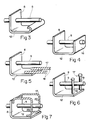
- Fig. 3 shows a simple and inexpensive to manufacture embodiment a mandrel 5 with flange-like disc 8 and plate 12, flange-like Disk 8 and plate 12 in a simple manner by a single fold Flat profile is reached.
- the flange is Disk 8 and the plate 12 formed in the same manner as in Fig. 3, wherein the end region of the plate 12 is angled again, as a result of which a web 16 is formed, which, like the flange-like disk 8, is penetrated by the mandrel 5 becomes.
- a good anchoring is particularly the Plate 12 reached in the concrete of the component.
- FIGS. 5 to 7 show the same structure as the embodiment of FIG. 3, consisting of flange-like disc 8, plate 12 and mandrel 5, with additional anchoring elements 17 are provided, which in the embodiment according to Fig. 5 are designed as reinforcing bars 18 which are firmly connected to the plate 12 are, in the embodiment according to FIG. 6 from anchoring bolts 19 exist, which are fixed vertically on the plate 12 and in the 7 are formed from reinforcement brackets 20 which are each attached to the plate 12 and to the flange-like disk 8. With These precautions will be better anchored in the concrete of each Component reached.
- Mandrel 5 and a sleeve 6 in the first component 1 or in the second component 2, both of which are separated by a joint 3.
- the mandrel 5 penetrates into the sleeve 6.
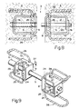
- Mandrel and sleeve have one flange-like disc 8 or 9, on each of which, as previously described, a plate 12 or 13 is attached.
- the plate 12 and the plate 13 are each via a web 16 with the rear region of the mandrel 5 or Sleeve 6 connected.
- a recess 24 on that of the corresponding flange Disc 8 and 9 each have the same distance.
- these recesses 24 each come the base webs 25 of an anchoring bracket 26 to lie, which are held by clamping action and in the concrete Condition a firm connection is created.
- the sleeve elements When creating components from concrete, the sleeve elements attached to the appropriate formwork walls. This is at the flange-like disc 9 attached a fastening device 27, which in Form of a flat profile is formed, with holes, for example Attachment to the formwork wall is equipped with nails.
- the front one and the rear opening of the sleeve 6 can be closed by covers so that concrete or cement milk is avoided in the inner part the sleeve arrives.
- the component 2 can then be concreted. After this When the concrete is set, component 2 is stripped.
- the adjacent one Part 1 will be created in a subsequent stage.
- the associated mandrels 5 of the mandrel elements into the concreted-in sleeves 6 of the sleeve elements inserted, including the corresponding covers the sleeve can be removed.
- openings 28 can be provided in the second plates 21 and 22.
- Mandrel elements and the sleeve elements were dimensioned accordingly be. This also applies to the flange-like disks and the plates.
- Mandrel and sleeve can be practically any matched Have cross section, the mandrel can have a hollow cross section or have a hybrid cross-section of several materials. The choice of materials also takes place depending on the application, being more advantageous Way corrosion-resistant steels are used.
- the components can be less Thickness, in particular the plate 12 or 13 can each very be arranged close to the surface of the corresponding component. Because of The greater the break resistance of the concrete can also be the number of the inventive Devices are reduced.
Claims (13)
- Dispositif servant à relier deux éléments, en particulier des éléments en béton, séparés par un joint, et à en absorber les forces transversales, ces éléments comportant respectivement une broche dont l'une des parties terminales est insérée dans le premier élément et une douille insérée dans le deuxième élément et dans laquelle pénètre l'autre des deux parties terminales de la broche, une face analogue à une bride étant disposée sur la broche et une autre sur la douille, près du joint, chacune de ces faces étant sensiblement perpendiculaire à la broche et à la douille et étant encastrée au moins en partie dans l'élément correspondant, caractérisé en ce que chacune des faces analogues à une bride (8, 9) est pourvue d'au moins une plaque (12 ou 13) qui pénètre dans l'élément considéré (1 ou 2), et en ce que la face (8, 9) analogue à une bride est orientée, dans l'élément correspondant (1, 2), de telle façon façon que la plaque (12, 13) placée dessus se trouve dans chaque cas du côté de la broche (5) ou de la douille (6) opposé au côté (10 ou 11) de la broche (5) ou de la douille (6) qui subit une contrainte de compression lors de la transmission des forces de réaction (A, B) à l'élément considéré (1, 2).
- Dispositif selon la revendication 1, caractérisé en ce que la plaque (12 ou 13) est disposée parallèlement à la broche (5) ou à la douille (6), et à une certaine distance de celles-ci.
- Dispositif selon la revendication 1 ou 2, caractérisé en ce que la face en forme de bride (8, 9) et la plaque (12, 13) sont faites d'une seule pièce qui forme un angle.
- Dispositif selon l'une des revendications 1 à 3, caractérisé en ce que la partie terminale de la plaque (12, 13) qui pénètre dans l'élément (1, 2) présente une partie recourbée (14).
- Dispositif selon l'une des revendications 1 à 4, caractérisé en ce que la partie terminale de la plaque (12, 13) opposée à la face en forme de bride (8, 9) est reliée par une aile (16) à la partie de la broche (5) ou de la douille (6) qui pénètre dans l'élément considéré (1, 2).
- Dispositif selon l'une des revendications 1 à 5, caractérisé en ce que la plaque (12, 13) est pourvue d'éléments d'ancrage supplémentaires (17).
- Dispositif selon l'une des revendications 1 à 6, caractérisé en ce qu'une deuxième plaque (21 ou 22), ayant sensiblement les mêmes dimensions que la plaque (12, 13), est placée sur la face en forme de bride (8, 9) en position symétrique de celle de la plaque (12, 13) par rapport à la broche (5) ou à la douille (6).
- Dispositif selon la revendication 7, caractérisé en ce que la plaque (12, 13), la face en forme de bride (8, 9) et la deuxième plaque (21, 22) sont formées d'une pièce par pliage.
- Dispositif selon la revendication 8, caractérisé en ce que les ailes (16, 23) sont formées grâce à d'autres pliages de la partie plane, ces ailes reliant la plaque (12, 13) et la deuxième plaque (21, 22) à la broche (5) ou à la douille (6), dans la partie terminale opposée à la face en forme de bride (8, 9).
- Dispositif selon l'une des revendications 7 à 9, caractérisé en ce que la plaque (12, 13) et la deuxième plaque (21, 22) présentent une encoche (24) dans chacun de leurs bords latéraux, ces encoches étant à des distances sensiblement égales de la face en forme de bride (8, 9) et pouvant recevoir une des deux branches de base (25), perpendiculaires à la plaque (12, 13) et à la deuxième plaque (21 ou 22), d'un étrier d'ancrage (26).
- Dispositif selon l'une des revendications 1 à 10, caractérisé en ce que la plaque (12, 13) et, le cas échéant, la deuxième plaque (21, 22), présentent au moins une ouverture (28).
- Dispositif selon l'une des revendications 1 à 11, caractérisé en ce qu'un dispositif de fixation (27), sous la forme d'un profilé plat, est monté sur la face en forme de bride (9) placée sur la douille (6).
- Dispositif selon l'une des revendications 1 à 12, caractérisé en ce qu'au moins l'extrémité de la douille (6) opposée à la face en forme de bride (9) est pourvue d'un recouvrement pouvant être glissé dessus.
Applications Claiming Priority (2)
| Application Number | Priority Date | Filing Date | Title |
|---|---|---|---|
| CH3154/95 | 1995-11-07 | ||
| CH315495 | 1995-11-07 |
Publications (3)
| Publication Number | Publication Date |
|---|---|
| EP0773324A1 EP0773324A1 (fr) | 1997-05-14 |
| EP0773324B1 true EP0773324B1 (fr) | 1998-07-22 |
| EP0773324B2 EP0773324B2 (fr) | 2006-04-05 |
Family
ID=4249787
Family Applications (1)
| Application Number | Title | Priority Date | Filing Date |
|---|---|---|---|
| EP96810712A Expired - Lifetime EP0773324B2 (fr) | 1995-11-07 | 1996-10-25 | Dispositif pour la connection et la transmission des forces transversales entre deux structures séparées par un joint |
Country Status (5)
| Country | Link |
|---|---|
| EP (1) | EP0773324B2 (fr) |
| AT (1) | ATE168730T1 (fr) |
| DE (1) | DE59600361D1 (fr) |
| DK (1) | DK0773324T4 (fr) |
| ES (1) | ES2121637T5 (fr) |
Cited By (3)
| Publication number | Priority date | Publication date | Assignee | Title |
|---|---|---|---|---|
| US6763646B1 (en) | 2000-09-21 | 2004-07-20 | Reto Bonomo | Method and element for introducing shear forces into a concrete body, and concrete body |
| EP2982807A1 (fr) | 2014-08-07 | 2016-02-10 | F.J. Aschwanden AG | Dispositif destiné à relier deux composants séparés par un joint |
| EP3339525A1 (fr) | 2016-12-22 | 2018-06-27 | F.J. Aschwanden AG | Dispositif destiné à relier deux composants séparés par un joint |
Families Citing this family (13)
| Publication number | Priority date | Publication date | Assignee | Title |
|---|---|---|---|---|
| CH691066A5 (de) * | 1996-06-19 | 2001-04-12 | Pecon Ag | Querkraftdornlagerung. |
| CH692991A5 (de) | 1997-11-17 | 2003-01-15 | Pecon Ag | Querkraftdornlagerung. |
| DE19964031A1 (de) * | 1999-12-30 | 2001-07-05 | Schoeck Bauteile Gmbh | Hülsen-/Dorn-Verbindung zwischen benachbarten Bauteilen |
| EP1329563B1 (fr) * | 2002-01-21 | 2006-08-23 | Industrieberatung Maier AG | Corps de répartition de charges |
| FI125954B (fi) | 2008-01-21 | 2016-04-29 | Peikko Finland Oy | Betonilaataston liikuntasaumajärjestelmä |
| FI120597B (fi) | 2008-01-21 | 2009-12-15 | Peikko Finland Oy | Betonilaataston liikuntasaumajärjestelmä |
| DE102008033585B4 (de) | 2008-07-17 | 2010-04-29 | Bs Ingenieure Ag | Schubdornverbindung |
| DE102010017046A1 (de) * | 2010-05-21 | 2011-11-24 | Max Frank Gmbh & Co Kg | Vorrichtung zum Verbinden von zwei durch eine Fuge getrennte Bauteile und zur Aufnahme von zwischen den Bauteilen auftretenden Querkräften |
| ITMI20121770A1 (it) * | 2012-10-18 | 2014-04-19 | Edilmatic S R L | Dispositivo di connessione per la connessione di elementi strutturali a base di calcestruzzo |
| EP3124697A1 (fr) * | 2015-07-30 | 2017-02-01 | F.J. Aschwanden AG | Dispositif a inserer dans un composant compose d'une masse de type mortier durcissable |
| CH713190A2 (de) * | 2016-12-01 | 2018-06-15 | Ikona Ag | Vorrichtung und Verfahren zur Verbindung von zwei Bauteilen in einer bestimmten relativen Ausrichtung sowie damit erstelltes Betonbauwerk. |
| EP3584367B1 (fr) | 2018-06-18 | 2020-09-30 | Plakabeton S.A. | Ensemble d'un dispositif de connexion |
| DE102020005274A1 (de) * | 2020-08-28 | 2022-03-03 | H-Bau Technik Gmbh | Vorrichtung zur Querkraftverbindung eines ersten Bauteils aus Beton mit einem zweiten Bauteil |
Citations (6)
| Publication number | Priority date | Publication date | Assignee | Title |
|---|---|---|---|---|
| DE609783C (de) * | 1935-02-23 | Marx & Traube G M B H | Zum Schleifen von Innenzylindern dienendes zylinderfuellendes Werkzeug | |
| EP0059171A1 (fr) * | 1981-02-23 | 1982-09-01 | Ulisse C. Aschwanden | Boulon et canon pour la prise et la transmission d'une force transversale |
| EP0328484A1 (fr) * | 1988-02-11 | 1989-08-16 | Egco Ag | Manchon de glissement pour la prise d'un boulon de force transversal |
| EP0489988A1 (fr) * | 1990-04-10 | 1992-06-17 | Ronald D. Shaw | Positionnement de douilles pour boulons dans des constructions en beton |
| WO1994029538A1 (fr) * | 1993-06-07 | 1994-12-22 | Walter Plehanoff | Ameliorations apportees a la construction de planchers en beton |
| DE4435922A1 (de) * | 1993-10-14 | 1995-05-04 | Anton H Erb | In Beton eingießbares Einzelteil einer Schubdornverbindungsanordnung |
Family Cites Families (4)
| Publication number | Priority date | Publication date | Assignee | Title |
|---|---|---|---|---|
| US2194718A (en) | 1938-06-25 | 1940-03-26 | Older Clifford | Concrete road joint |
| US2494869A (en) * | 1945-01-29 | 1950-01-17 | William S Godwin | Dowel assembly for concrete road joints |
| CH651090A5 (de) * | 1980-01-04 | 1985-08-30 | Ulisse Claudio Aschwanden | Dorn und huelse zur verbindung von bauteilen des hoch- und tiefbaues. |
| DE59207813D1 (de) * | 1992-02-05 | 1997-02-13 | Claude Meyers | Verbindungs- und Druckverteilerelement für Betonbauteile |
-
1996
- 1996-10-25 ES ES96810712T patent/ES2121637T5/es not_active Expired - Lifetime
- 1996-10-25 AT AT96810712T patent/ATE168730T1/de active
- 1996-10-25 DK DK96810712T patent/DK0773324T4/da active
- 1996-10-25 DE DE59600361T patent/DE59600361D1/de not_active Expired - Lifetime
- 1996-10-25 EP EP96810712A patent/EP0773324B2/fr not_active Expired - Lifetime
Patent Citations (6)
| Publication number | Priority date | Publication date | Assignee | Title |
|---|---|---|---|---|
| DE609783C (de) * | 1935-02-23 | Marx & Traube G M B H | Zum Schleifen von Innenzylindern dienendes zylinderfuellendes Werkzeug | |
| EP0059171A1 (fr) * | 1981-02-23 | 1982-09-01 | Ulisse C. Aschwanden | Boulon et canon pour la prise et la transmission d'une force transversale |
| EP0328484A1 (fr) * | 1988-02-11 | 1989-08-16 | Egco Ag | Manchon de glissement pour la prise d'un boulon de force transversal |
| EP0489988A1 (fr) * | 1990-04-10 | 1992-06-17 | Ronald D. Shaw | Positionnement de douilles pour boulons dans des constructions en beton |
| WO1994029538A1 (fr) * | 1993-06-07 | 1994-12-22 | Walter Plehanoff | Ameliorations apportees a la construction de planchers en beton |
| DE4435922A1 (de) * | 1993-10-14 | 1995-05-04 | Anton H Erb | In Beton eingießbares Einzelteil einer Schubdornverbindungsanordnung |
Non-Patent Citations (1)
| Title |
|---|
| Broschüre"CRET-10 Querkraftdorn" F.J- Aschwanden AG, 3250 Lyss, Switzerland, 1994 * |
Cited By (3)
| Publication number | Priority date | Publication date | Assignee | Title |
|---|---|---|---|---|
| US6763646B1 (en) | 2000-09-21 | 2004-07-20 | Reto Bonomo | Method and element for introducing shear forces into a concrete body, and concrete body |
| EP2982807A1 (fr) | 2014-08-07 | 2016-02-10 | F.J. Aschwanden AG | Dispositif destiné à relier deux composants séparés par un joint |
| EP3339525A1 (fr) | 2016-12-22 | 2018-06-27 | F.J. Aschwanden AG | Dispositif destiné à relier deux composants séparés par un joint |
Also Published As
| Publication number | Publication date |
|---|---|
| DK0773324T4 (da) | 2006-08-14 |
| DE59600361D1 (de) | 1998-08-27 |
| EP0773324B2 (fr) | 2006-04-05 |
| ES2121637T3 (es) | 1998-12-01 |
| ATE168730T1 (de) | 1998-08-15 |
| DK0773324T3 (da) | 1999-04-26 |
| EP0773324A1 (fr) | 1997-05-14 |
| ES2121637T5 (es) | 2006-11-16 |
Similar Documents
| Publication | Publication Date | Title |
|---|---|---|
| EP0773324B1 (fr) | Dispositif pour la connection et la transmission des forces transversales entre deux structures séparées par un joint | |
| EP1007809B1 (fr) | Dispositif de renfort pour structures porteuses | |
| EP0040815B1 (fr) | Poutre composite dans la construction préfabriquée | |
| CH678959A5 (fr) | ||
| EP0410079B1 (fr) | Coffrage de raccordement pour panneaux en béton reliés | |
| DE10310715A1 (de) | Erfindung betreffend Bauteile als Bewehrungselemente sowie daraus hergestellte Betonteile | |
| CH678204A5 (fr) | ||
| EP0193494B1 (fr) | Elément de liaison et de répartition des contraintes pour éléments de construction en béton | |
| EP0023042B1 (fr) | Elément de plancher préfabriqué pour planchers de bâtiments | |
| EP2055845A2 (fr) | Elément de montage de dalles en porte-à-faux | |
| EP2146004B1 (fr) | Connexion de broche travaillant en cisaillement | |
| DE19514685C2 (de) | Anordnung von mehreren Pfahlschuhen | |
| EP0554483A1 (fr) | Elément de liaison et de répartition des contraintes pour éléments de construction en béton | |
| EP0250612A1 (fr) | Planche pour un échafaudage à érection rapide | |
| EP3502350A1 (fr) | Raccordement de deux éléments de paroi de guidage | |
| EP2516761B1 (fr) | Dispositif permettant de raccorder deux éléments de construction séparés par un joint et d'absorber des efforts de cisaillement apparaissant entre les éléments de construction | |
| DE19739446A1 (de) | Querkraftlager | |
| EP2982807B1 (fr) | Dispositif destiné à relier deux composants séparés par un joint | |
| EP0506216A1 (fr) | Dispositif de fixation des rails de guidage | |
| DE102006002277A1 (de) | Befestigungsklammer | |
| DE10393392T5 (de) | Anordnung zur Herstellung einer Verbindung zwischen einem Balken und einer Konsole | |
| DE3444801C2 (fr) | ||
| CH662609A5 (de) | Spannbeton- oder stahlbetonbiegetraeger. | |
| DE3130445A1 (de) | Beschlag zum querkraftbelastbaren anschluss an die stirnseite von holzbalken | |
| DE3518811A1 (de) | Knotenplatte |
Legal Events
| Date | Code | Title | Description |
|---|---|---|---|
| PUAI | Public reference made under article 153(3) epc to a published international application that has entered the european phase |
Free format text: ORIGINAL CODE: 0009012 |
|
| AK | Designated contracting states |
Kind code of ref document: A1 Designated state(s): AT BE CH DE DK ES FR GB IE IT LI NL SE |
|
| 17P | Request for examination filed |
Effective date: 19970606 |
|
| GRAG | Despatch of communication of intention to grant |
Free format text: ORIGINAL CODE: EPIDOS AGRA |
|
| 17Q | First examination report despatched |
Effective date: 19971205 |
|
| GRAG | Despatch of communication of intention to grant |
Free format text: ORIGINAL CODE: EPIDOS AGRA |
|
| GRAH | Despatch of communication of intention to grant a patent |
Free format text: ORIGINAL CODE: EPIDOS IGRA |
|
| GRAH | Despatch of communication of intention to grant a patent |
Free format text: ORIGINAL CODE: EPIDOS IGRA |
|
| GRAA | (expected) grant |
Free format text: ORIGINAL CODE: 0009210 |
|
| AK | Designated contracting states |
Kind code of ref document: B1 Designated state(s): AT BE CH DE DK ES FR GB IE IT LI NL SE |
|
| REF | Corresponds to: |
Ref document number: 168730 Country of ref document: AT Date of ref document: 19980815 Kind code of ref document: T |
|
| REG | Reference to a national code |
Ref country code: CH Ref legal event code: NV Representative=s name: BOVARD AG PATENTANWAELTE Ref country code: CH Ref legal event code: EP |
|
| ITPR | It: changes in ownership of a european patent |
Owner name: CESSIONE EPO REG. 20;NIVO AG |
|
| REF | Corresponds to: |
Ref document number: 59600361 Country of ref document: DE Date of ref document: 19980827 |
|
| GBT | Gb: translation of ep patent filed (gb section 77(6)(a)/1977) |
Effective date: 19981006 |
|
| REG | Reference to a national code |
Ref country code: IE Ref legal event code: FG4D Free format text: GERMAN |
|
| ET | Fr: translation filed | ||
| REG | Reference to a national code |
Ref country code: ES Ref legal event code: FG2A Ref document number: 2121637 Country of ref document: ES Kind code of ref document: T3 |
|
| RAP2 | Party data changed (patent owner data changed or rights of a patent transferred) |
Owner name: NIVO AG |
|
| NLT2 | Nl: modifications (of names), taken from the european patent patent bulletin |
Owner name: NIVO AG |
|
| REG | Reference to a national code |
Ref country code: DK Ref legal event code: T3 |
|
| PLBQ | Unpublished change to opponent data |
Free format text: ORIGINAL CODE: EPIDOS OPPO |
|
| PLBI | Opposition filed |
Free format text: ORIGINAL CODE: 0009260 |
|
| REG | Reference to a national code |
Ref country code: CH Ref legal event code: PUE Owner name: F.J. ASCHWANDEN AG TRANSFER- NIVO AG |
|
| PLBF | Reply of patent proprietor to notice(s) of opposition |
Free format text: ORIGINAL CODE: EPIDOS OBSO |
|
| 26 | Opposition filed |
Opponent name: EGCO AG Effective date: 19990420 |
|
| REG | Reference to a national code |
Ref country code: GB Ref legal event code: 732E |
|
| REG | Reference to a national code |
Ref country code: FR Ref legal event code: TP |
|
| NLS | Nl: assignments of ep-patents |
Owner name: NIVO AG |
|
| PLBF | Reply of patent proprietor to notice(s) of opposition |
Free format text: ORIGINAL CODE: EPIDOS OBSO |
|
| PLBF | Reply of patent proprietor to notice(s) of opposition |
Free format text: ORIGINAL CODE: EPIDOS OBSO |
|
| PLAW | Interlocutory decision in opposition |
Free format text: ORIGINAL CODE: EPIDOS IDOP |
|
| APAC | Appeal dossier modified |
Free format text: ORIGINAL CODE: EPIDOS NOAPO |
|
| APAE | Appeal reference modified |
Free format text: ORIGINAL CODE: EPIDOS REFNO |
|
| REG | Reference to a national code |
Ref country code: GB Ref legal event code: IF02 |
|
| APAC | Appeal dossier modified |
Free format text: ORIGINAL CODE: EPIDOS NOAPO |
|
| APBU | Appeal procedure closed |
Free format text: ORIGINAL CODE: EPIDOSNNOA9O |
|
| APAH | Appeal reference modified |
Free format text: ORIGINAL CODE: EPIDOSCREFNO |
|
| PUAH | Patent maintained in amended form |
Free format text: ORIGINAL CODE: 0009272 |
|
| STAA | Information on the status of an ep patent application or granted ep patent |
Free format text: STATUS: PATENT MAINTAINED AS AMENDED |
|
| 27A | Patent maintained in amended form |
Effective date: 20060405 |
|
| AK | Designated contracting states |
Kind code of ref document: B2 Designated state(s): AT BE CH DE DK ES FR GB IE IT LI NL SE |
|
| REG | Reference to a national code |
Ref country code: CH Ref legal event code: AEN Free format text: AUFRECHTERHALTUNG DES PATENTES IN GEAENDERTER FORM |
|
| NLR2 | Nl: decision of opposition |
Effective date: 20060405 |
|
| GBTA | Gb: translation of amended ep patent filed (gb section 77(6)(b)/1977) |
Effective date: 20060621 |
|
| REG | Reference to a national code |
Ref country code: SE Ref legal event code: RPEO |
|
| REG | Reference to a national code |
Ref country code: DK Ref legal event code: T4 |
|
| NLR3 | Nl: receipt of modified translations in the netherlands language after an opposition procedure | ||
| REG | Reference to a national code |
Ref country code: ES Ref legal event code: DC2A Date of ref document: 20060703 Kind code of ref document: T5 |
|
| ET3 | Fr: translation filed ** decision concerning opposition | ||
| REG | Reference to a national code |
Ref country code: CH Ref legal event code: PUE Owner name: F.J. ASCHWANDEN AG Free format text: HALFEN SWISS AG#INDUSTRIESTRASSE 32#8108 DAELLIKON (CH) -TRANSFER TO- F.J. ASCHWANDEN AG#GRENZSTRASSE 24#3250 LYSS (CH) Ref country code: CH Ref legal event code: PFA Owner name: HALFEN SWISS AG Free format text: NIVO AG#GRENZSTRASSE 24#3250 LYSS (CH) -TRANSFER TO- HALFEN SWISS AG#INDUSTRIESTRASSE 32#8108 DAELLIKON (CH) |
|
| NLS | Nl: assignments of ep-patents |
Owner name: F.J. ASCHWANDEN AG Effective date: 20080821 |
|
| NLT1 | Nl: modifications of names registered in virtue of documents presented to the patent office pursuant to art. 16 a, paragraph 1 |
Owner name: HALFEN SWISS AG |
|
| REG | Reference to a national code |
Ref country code: GB Ref legal event code: 732E |
|
| BECA | Be: change of holder's address |
Owner name: F.J. ASCHWANDEN A.G.GRENZSTRASSE 24, CH-3250 LYSS Effective date: 20081202 |
|
| BECH | Be: change of holder |
Owner name: F.J. ASCHWANDEN A.G. Effective date: 20081202 |
|
| REG | Reference to a national code |
Ref country code: FR Ref legal event code: TP |
|
| REG | Reference to a national code |
Ref country code: ES Ref legal event code: PC2A |
|
| REG | Reference to a national code |
Ref country code: CH Ref legal event code: PFA Owner name: F.J. ASCHWANDEN AG Free format text: F.J. ASCHWANDEN AG#GRENZSTRASSE 24#3250 LYSS (CH) -TRANSFER TO- F.J. ASCHWANDEN AG#GRENZSTRASSE 24#3250 LYSS (CH) |
|
| REG | Reference to a national code |
Ref country code: FR Ref legal event code: PLFP Year of fee payment: 20 |
|
| PGFP | Annual fee paid to national office [announced via postgrant information from national office to epo] |
Ref country code: DK Payment date: 20151021 Year of fee payment: 20 |
|
| PGFP | Annual fee paid to national office [announced via postgrant information from national office to epo] |
Ref country code: DE Payment date: 20151022 Year of fee payment: 20 Ref country code: IE Payment date: 20151028 Year of fee payment: 20 Ref country code: IT Payment date: 20151026 Year of fee payment: 20 Ref country code: CH Payment date: 20151013 Year of fee payment: 20 Ref country code: GB Payment date: 20151021 Year of fee payment: 20 |
|
| PGFP | Annual fee paid to national office [announced via postgrant information from national office to epo] |
Ref country code: NL Payment date: 20151021 Year of fee payment: 20 Ref country code: ES Payment date: 20151021 Year of fee payment: 20 Ref country code: SE Payment date: 20151021 Year of fee payment: 20 Ref country code: AT Payment date: 20151022 Year of fee payment: 20 Ref country code: FR Payment date: 20151023 Year of fee payment: 20 Ref country code: BE Payment date: 20151021 Year of fee payment: 20 |
|
| REG | Reference to a national code |
Ref country code: DE Ref legal event code: R071 Ref document number: 59600361 Country of ref document: DE |
|
| REG | Reference to a national code |
Ref country code: NL Ref legal event code: MK Effective date: 20161024 |
|
| REG | Reference to a national code |
Ref country code: CH Ref legal event code: PL Ref country code: DK Ref legal event code: EUP Effective date: 20161025 |
|
| REG | Reference to a national code |
Ref country code: GB Ref legal event code: PE20 Expiry date: 20161024 |
|
| REG | Reference to a national code |
Ref country code: SE Ref legal event code: EUG |
|
| REG | Reference to a national code |
Ref country code: IE Ref legal event code: MK9A |
|
| REG | Reference to a national code |
Ref country code: AT Ref legal event code: MK07 Ref document number: 168730 Country of ref document: AT Kind code of ref document: T Effective date: 20161025 |
|
| PG25 | Lapsed in a contracting state [announced via postgrant information from national office to epo] |
Ref country code: GB Free format text: LAPSE BECAUSE OF EXPIRATION OF PROTECTION Effective date: 20161024 Ref country code: IE Free format text: LAPSE BECAUSE OF EXPIRATION OF PROTECTION Effective date: 20161025 |
|
| REG | Reference to a national code |
Ref country code: ES Ref legal event code: FD2A Effective date: 20170201 |
|
| PG25 | Lapsed in a contracting state [announced via postgrant information from national office to epo] |
Ref country code: ES Free format text: LAPSE BECAUSE OF EXPIRATION OF PROTECTION Effective date: 20161026 |