EP0773324B1 - Device for the connection and transfer of shearing forces between two building elements separated by a joint - Google Patents
Device for the connection and transfer of shearing forces between two building elements separated by a joint Download PDFInfo
- Publication number
- EP0773324B1 EP0773324B1 EP96810712A EP96810712A EP0773324B1 EP 0773324 B1 EP0773324 B1 EP 0773324B1 EP 96810712 A EP96810712 A EP 96810712A EP 96810712 A EP96810712 A EP 96810712A EP 0773324 B1 EP0773324 B1 EP 0773324B1
- Authority
- EP
- European Patent Office
- Prior art keywords
- plate
- flange
- sheath
- bolt
- disk
- Prior art date
- Legal status (The legal status is an assumption and is not a legal conclusion. Google has not performed a legal analysis and makes no representation as to the accuracy of the status listed.)
- Expired - Lifetime
Links
Images

Classifications
-
- E—FIXED CONSTRUCTIONS
- E01—CONSTRUCTION OF ROADS, RAILWAYS, OR BRIDGES
- E01C—CONSTRUCTION OF, OR SURFACES FOR, ROADS, SPORTS GROUNDS, OR THE LIKE; MACHINES OR AUXILIARY TOOLS FOR CONSTRUCTION OR REPAIR
- E01C11/00—Details of pavings
- E01C11/02—Arrangement or construction of joints; Methods of making joints; Packing for joints
- E01C11/04—Arrangement or construction of joints; Methods of making joints; Packing for joints for cement concrete paving
- E01C11/14—Dowel assembly ; Design or construction of reinforcements in the area of joints
Definitions
- the present invention relates to a device for Connect and absorb transverse forces from two separated by a joint Components, in particular made of concrete, according to the preamble of the claim 1.
- Such devices are used to connect components of the Civil engineering such as roof panels, floor panels, ceilings, walls, beams, Columns, retaining walls or parts thereof with one another or with other components used. In most cases, these components are made of concrete, however, other materials are also conceivable.
- the mandrel In addition to the possibility of transverse to the longitudinal axis considerable To absorb forces, the mandrel must be freely movable in the sleeve and remain so that the components are under the influence of different temperatures as well as as a result of shrinkage and creep influences expand and contract.
- the object of the invention is now the extremely high Pressing the material of the corresponding components under the mandrel and to further reduce the size of the sleeve at the joint edge.
- This configuration of the holder of the mandrel and the sleeve is a direct relief of the mandrel and the sleeve before entering the Component reached. This relief takes place via the one arranged at the edge of the joint flange - like disc, the force absorbed by this disc in the plate connected to the disc is transferred from and into this surrounding material, for example, is transferred into the concrete.
- This arrangement according to the invention is used for power transmission a very large area of the surrounding material of the components, for example of the concrete, which makes it a much larger one Breaking resistance of the material of the components can be achieved.
- a simple and inexpensive manufacture of the device will achieved by the flange-like disc and the plate of mandrel and sleeve assembly be formed from one piece, for example by folding a flat profile is reached.
- the end region projecting into the component can advantageously of the plate have a bent part, thereby anchoring the plate in the component is improved.
- An advantageous embodiment of the invention is that a symmetrically arranged with respect to the mandrel or the sleeve to the plate second plate is attached to the flange-shaped disc, which is advantageous Way has the same dimensions as the plate. This can help alternating force directions optimally absorbed on the same component are additionally avoided that the inventive according to a construction site Device can be incorrectly installed, for example, the The plate comes to rest on the "wrong" side of the mandrel or sleeve.
- first component 1 and 2 each show a section of a first component 1 and a second component 2.
- Components 1 and 2 for example consist of concrete, are separated by a joint 3. in the An end region 4 of a mandrel 5 is embedded in the first component 1.
- the second Component 2 is a substantially tubular sleeve 6, in which the other end region 7 of the mandrel 5 penetrates.
- Both components 1 and 2 can be in the longitudinal axis direction of the mandrel 5 or the sleeve 6 move relative to each other, for example for recording of thermal expansion while being fixed across the mandrel 5 or the sleeve 6 are held.
- a flange-like disk 8 and 9 is arranged on the edge regions of the components 1 forming the joint 3 and 2.
- These flange-like Disks 8 and 9 are each perpendicular to mandrel 5 and sleeve 7.
- Die flange-like disc 8 is penetrated by the mandrel 5 and is fixed with it connected, which is done for example by welding.
- the flange-like Disk 9 is in turn penetrated by the sleeve 6 and is with this also firmly connected.
- the second component 2 is a support element and the first component 1 is a bridge element, which acts on the concrete of the component 2 reaction force to be transmitted from the sleeve 6 in Fig. 1 in the direction of arrow B, while that to be transferred to the concrete of component 1 Reactive force of the mandrel 5 acts in the direction of arrow A.
- the pressure-loaded side 11 below, while for the mandrel 5 is the pressure loaded side 10 above.
- Plate 12 or 13 attached, which protrudes into the respective component 1 or 2.
- the two plates 12 and 13 are aligned parallel to the mandrel 5 and the sleeve 6.
- the plates 12 and 13 come in the respective component 1 and 2 respectively lie that they are the pressure-loaded side 10 of the mandrel 5 or the pressure-loaded Side 11 of the sleeve 6 are opposite.
- the plates 12 and 13 are each spaced from the mandrel 5 or the sleeve 6.
- the flange-like disc 8 Peak load that occurs at the joint-side edge of component 1 is added and advantageously on the concrete of the component via the plate 12 1 transferred. This will cause excessive local concrete pressures of component 1 avoided in particular in the joint-side edge area. In the ⁇ In the same way, the peak load is transmitted on the joint side Edge of the component 2 on the flange-like disc 9 on the plate 13 and from this to the concrete. This can increase the risk of breakouts Concrete on the edge of the joint can be avoided.
- flange-like disks 8 and 9 plates 12 and 13 and their distance from the mandrel 5 or sleeve 6 are dimensioned accordingly.
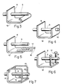
- Fig. 3 shows a simple and inexpensive to manufacture embodiment a mandrel 5 with flange-like disc 8 and plate 12, flange-like Disk 8 and plate 12 in a simple manner by a single fold Flat profile is reached.
- the flange is Disk 8 and the plate 12 formed in the same manner as in Fig. 3, wherein the end region of the plate 12 is angled again, as a result of which a web 16 is formed, which, like the flange-like disk 8, is penetrated by the mandrel 5 becomes.
- a good anchoring is particularly the Plate 12 reached in the concrete of the component.
- FIGS. 5 to 7 show the same structure as the embodiment of FIG. 3, consisting of flange-like disc 8, plate 12 and mandrel 5, with additional anchoring elements 17 are provided, which in the embodiment according to Fig. 5 are designed as reinforcing bars 18 which are firmly connected to the plate 12 are, in the embodiment according to FIG. 6 from anchoring bolts 19 exist, which are fixed vertically on the plate 12 and in the 7 are formed from reinforcement brackets 20 which are each attached to the plate 12 and to the flange-like disk 8. With These precautions will be better anchored in the concrete of each Component reached.
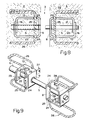
- Mandrel 5 and a sleeve 6 in the first component 1 or in the second component 2, both of which are separated by a joint 3.
- the mandrel 5 penetrates into the sleeve 6.
- Mandrel and sleeve have one flange-like disc 8 or 9, on each of which, as previously described, a plate 12 or 13 is attached.
- the plate 12 and the plate 13 are each via a web 16 with the rear region of the mandrel 5 or Sleeve 6 connected.
- a recess 24 on that of the corresponding flange Disc 8 and 9 each have the same distance.
- these recesses 24 each come the base webs 25 of an anchoring bracket 26 to lie, which are held by clamping action and in the concrete Condition a firm connection is created.
- the sleeve elements When creating components from concrete, the sleeve elements attached to the appropriate formwork walls. This is at the flange-like disc 9 attached a fastening device 27, which in Form of a flat profile is formed, with holes, for example Attachment to the formwork wall is equipped with nails.
- the front one and the rear opening of the sleeve 6 can be closed by covers so that concrete or cement milk is avoided in the inner part the sleeve arrives.
- the component 2 can then be concreted. After this When the concrete is set, component 2 is stripped.
- the adjacent one Part 1 will be created in a subsequent stage.
- the associated mandrels 5 of the mandrel elements into the concreted-in sleeves 6 of the sleeve elements inserted, including the corresponding covers the sleeve can be removed.
- openings 28 can be provided in the second plates 21 and 22.
- Mandrel elements and the sleeve elements were dimensioned accordingly be. This also applies to the flange-like disks and the plates.
- Mandrel and sleeve can be practically any matched Have cross section, the mandrel can have a hollow cross section or have a hybrid cross-section of several materials. The choice of materials also takes place depending on the application, being more advantageous Way corrosion-resistant steels are used.
- the components can be less Thickness, in particular the plate 12 or 13 can each very be arranged close to the surface of the corresponding component. Because of The greater the break resistance of the concrete can also be the number of the inventive Devices are reduced.
Landscapes
- Engineering & Computer Science (AREA)
- Architecture (AREA)
- Civil Engineering (AREA)
- Structural Engineering (AREA)
- Joining Of Building Structures In Genera (AREA)
- Joints Allowing Movement (AREA)
- Building Environments (AREA)
- Roof Covering Using Slabs Or Stiff Sheets (AREA)
- Seal Device For Vehicle (AREA)
- Automatic Cycles, And Cycles In General (AREA)
- Snaps, Bayonet Connections, Set Pins, And Snap Rings (AREA)
- Insertion Pins And Rivets (AREA)
Abstract
Description
Die vorliegende Erfindung bezieht sich auf eine Vorrichtung zum
Verbinden und zur Aufnahme von Querkräften von zwei durch eine Fuge getrennten
Bauteilen, insbesondere aus Beton, gemäss dem Oberbegriff des Patentanspruches
1.The present invention relates to a device for
Connect and absorb transverse forces from two separated by a joint
Components, in particular made of concrete, according to the preamble of the
Derartige Vorrichtungen werden zur Verbindung von Bauteilen des Hoch- und Tiefbaues wie Dachplatten, Bodenplatten, Decken, Wände, Träger, Stützen, Stützmauern oder Teilen hiervon miteinander oder mit anderen Bauteilen verwendet. Diese Bauteile sind in den meisten Fällen aus Beton gefertigt, es sind aber auch andere Materialien denkbar. Hierzu wird der Hülsenteil in einem der zu verbindenden Bauteile, der Dornteil im damit zu verbindenden Bauteil derart angeordnet, dass der Dorn aus dem betreffenden Bauteil vorsteht und im Endzustand in die im anderen Bauteil angeordnete Hülse eindringt. Dadurch können die zwischen den Bauteilen auftretenden Querkräfte übertragen werden. Neben der Möglichkeit, quer zur Längsachse erhebliche Kräfte aufzunehmen, muss der Dorn in der Hülse längs frei verschieblich sein und bleiben, damit sich die Bauteile unter dem Einfluss unterschiedlicher Temperaturen sowie auch in Folge von Schwind- und Kriecheinflüssen zwangslos ausdehnen und zusammenziehen können.Such devices are used to connect components of the Civil engineering such as roof panels, floor panels, ceilings, walls, beams, Columns, retaining walls or parts thereof with one another or with other components used. In most cases, these components are made of concrete, however, other materials are also conceivable. For this, the sleeve part in one of the components to be connected, the mandrel part in the component to be connected Component arranged such that the mandrel protrudes from the component in question and in the final state penetrates into the sleeve arranged in the other component. As a result, the transverse forces occurring between the components be transmitted. In addition to the possibility of transverse to the longitudinal axis considerable To absorb forces, the mandrel must be freely movable in the sleeve and remain so that the components are under the influence of different temperatures as well as as a result of shrinkage and creep influences expand and contract.
Das Hauptproblem bei derartigen Vorrichtungen zur Verbindung von Bauteilen, beispielsweise aus Beton, sind die sehr hohen lokalen Betonpressungen unter dem Stahldorn am Fugenrand. Hierbei besteht die Gefahr des Ausbrechens des Betons am Fugenrand, womit eine akute Gefährdung der Tragsicherheit der Dornkonstruktion auftreten kann. Um diese Betonpressungen in zulässigen Grenzen zu halten, müsste bei einer einfachen Dorn-Hülsen-Anordnung zur Verbindung von zwei Bauteilen eine grosse Zahl von Dornen und Hülsen angeordnet werden. Da die Dorne und Hülsen aus einem korrosionsfesten Material, beziehungsweise aus einem korrosionsgeschützten Material bestehen müssen, wird eine derartige Lösung teuer, wobei auch der Arbeitsaufwand zum Verlegen dieser Dorne und Hülsen gross ist. The main problem with such devices for connecting Components, for example made of concrete, are the very high local concrete pressures under the steel mandrel at the joint edge. Here there is a risk of Breaking out of the concrete at the edge of the joint, which poses an acute risk to the Strength of the mandrel construction can occur. To these concrete pressings To keep it within permissible limits would have to be the case with a simple mandrel-sleeve arrangement a large number of thorns for connecting two components and sleeves are arranged. Because the mandrels and sleeves are made of a corrosion-resistant Material, or from a corrosion-protected material Such a solution must be expensive, and the workload is great for laying these mandrels and sleeves.
Eine Möglichkeit, die Betonpressungen in zulässigen Grenzen zu halten, besteht darin, dass durch Anordnen eines massiven Lagerkörpers zwischen dem Dorn bzw. der Hülse und dem umgebenden Beton die auftretende Kraft über eine grössere Oberfläche auf den Beton übertragen wird. Derartige Lagerkörper sind beispielsweise in der US-A-2 194 718 dargestellt. Da die hier gezeigten Lagerkörper insbesondere versteift wurden, treten druckseitig immer noch örtlich hohe Betonpressungen auf, da die Einleitung der Kraft nicht optimal ist.One way to limit the concrete pressures within permissible limits hold, is that by placing a massive bearing body between the mandrel or the sleeve and the surrounding concrete the occurring Force is transferred to the concrete over a larger surface. Such Bearing bodies are shown, for example, in US-A-2 194 718. Because this one Bearing body shown were stiffened in particular, always occur on the pressure side local high concrete pressures, since the introduction of the force is not optimal is.
In der EP-B-0 032 105 sind ebenfalls entsprechende massive Lagerkörper gezeigt, die gegenüber dem Dorn bzw. der Hülse elastisch nachgiebiger sind, wodurch die auftretenden Spitzenwerte der Betonpressung verkleinert werden und die Querkräfte gleichmässiger übertragen werden können.Corresponding massive bearing bodies are also in EP-B-0 032 105 shown, the elastically more flexible compared to the mandrel or the sleeve are, which reduces the peak values of the concrete pressure that occur and the lateral forces can be transferred more evenly.
Die Aufgabe der Erfindung besteht nun darin, die extrem hohen Pressungen des Materials der entsprechenden Bauteile unter dem Dorn und der Hülse am Fugenrand weiter zu verkleinern.The object of the invention is now the extremely high Pressing the material of the corresponding components under the mandrel and to further reduce the size of the sleeve at the joint edge.
Erfindungsgemäss erfolgt die Lösung dieser Aufgabe durch die in
der Kennzeichnung des Anspruchs 1 angegebenen Merkmale.According to the invention, this object is achieved by the in
the marking of
Durch diese Ausgestaltung der Halterung des Dorns und der Hülse wird eine direkte Entlastung des Dorns und der Hülse vor dem Eintritt in den Bauteil erreicht. Diese Entlastung erfolgt über die am Fugenrand angeordnete flanschartige Scheibe, wobei die von dieser Scheibe aufgenommene Kraft in die mit der Scheibe verbundene Platte übergeleitet und von dieser in das diese umgebende Material, beispielsweise in den Beton übertragen wird.This configuration of the holder of the mandrel and the sleeve is a direct relief of the mandrel and the sleeve before entering the Component reached. This relief takes place via the one arranged at the edge of the joint flange - like disc, the force absorbed by this disc in the plate connected to the disc is transferred from and into this surrounding material, for example, is transferred into the concrete.
Durch diese erfindungsgemässe Anordnung wird für die Kraftübertragung ein sehr grosser Bereich des umgebenden Materials der Bauteile, beispielsweise des Betons, einbezogen, wodurch ein wesentlich grösserer Bruchwiderstand des Materials der Bauteile erreichbar ist.This arrangement according to the invention is used for power transmission a very large area of the surrounding material of the components, for example of the concrete, which makes it a much larger one Breaking resistance of the material of the components can be achieved.
Eine einfache und kostengünstige Herstellung der Vorrichtung wird erreicht, indem die flanschartige Scheibe und die Platte von Dorn- und Hülsenanordnung aus einem Stück gebildet werden, was beispielsweise durch Abkantung eines Flachprofils erreicht wird.A simple and inexpensive manufacture of the device will achieved by the flange-like disc and the plate of mandrel and sleeve assembly be formed from one piece, for example by folding a flat profile is reached.
In vorteilhafter Weise kann der in den Bauteil hineinragende Endbereich der Platte einen umgebogenen Teil aufweisen, wodurch die Verankerung der Platte im Bauteil verbessert wird.The end region projecting into the component can advantageously of the plate have a bent part, thereby anchoring the plate in the component is improved.
Zur weiteren Verbesserung der Verankerung kann der von der flanschförmigen Scheibe abgewandte Endbereich der Platte mit dem in den entsprechenden Bauteil hineinragenden Bereich der Hülse bzw. des Dorns verbunden sein, was beispielsweise über einen Steg erreicht werden kann.To further improve the anchoring of the end region of the plate facing away from the flange-shaped disk and with the in the corresponding component projecting region of the sleeve or the mandrel connected be what can be achieved, for example, via a web.
Eine vorteilhafte Ausgestaltung der Erfindung besteht darin, dass bezüglich des Dorns oder der Hülse zur Platte eine symmetrisch angeordnete zweite Platte an der flanschförmigen Scheibe angebracht ist, die in vorteilhafter Weise die gleichen Abmessungen aufweist wie die Platte. Dadurch können allfällig wechselnde Kraftrichtungen am gleichen Bauteil optimal aufgenommen werden, zusätzlich wird vermieden, dass auf einer Baustelle die erfindungsgemässe Vorrichtung falsch montiert werden kann, indem beispielsweise die Platte auf die ,,falsche" Seite des Dorns bzw. der Hülse zu liegen kommt.An advantageous embodiment of the invention is that a symmetrically arranged with respect to the mandrel or the sleeve to the plate second plate is attached to the flange-shaped disc, which is advantageous Way has the same dimensions as the plate. This can help alternating force directions optimally absorbed on the same component are additionally avoided that the inventive according to a construction site Device can be incorrectly installed, for example, the The plate comes to rest on the "wrong" side of the mandrel or sleeve.
Weitere vorteilhafte Ausgestaltungen der Erfindung ergeben sich aus den weiteren abhängigen Ansprüchen.Further advantageous embodiments of the invention result from the further dependent claims.
Ausführungsformen der erfindungsgemässen Vorrichtung werden nachfolgend anhand der beiliegenden Zeichnung beispielhaft näher erläutert.Embodiments of the device according to the invention are explained in more detail below with reference to the accompanying drawing.
Es zeigt
In Fig. 1 und Fig. 2 ist jeweils ein Ausschnitt eines ersten Bauteils 1
und eines zweiten Bauteils 2 dargestellt. Die Bauteile 1 und 2, die beispielsweise
aus Beton bestehen, sind durch eine Fuge 3 voneinander getrennt. Im
ersten Bauteil 1 ist ein Endbereich 4 eines Dorns 5 eingelassen. Im zweiten
Bauteil 2 ist eine im wesentlichen rohrförmige Hülse 6 eingelassen, in welche
der andere Endbereich 7 des Dorns 5 eindringt. Durch diese Verbindung der
beiden Bauteile 1 und 2 können sich diese in Längsachsenrichtung des Dorns
5 bzw. der Hülse 6 relativ zueinander bewegen, beispielsweise zur Aufnahme
von Wärmeausdehnungen, während sie quer zum Dorn 5 bzw. der Hülse 6 fix
gehalten sind.1 and 2 each show a section of a
Jeweils an den die Fuge 3 bildenden Randbereichen der Bauteile 1
und 2 ist eine flanschartige Scheibe 8 bzw. 9 angeordnet. Diese flanschartigen
Scheiben 8 und 9 stehen jeweils rechtwinklig zu Dorn 5 bzw. Hülse 7. Die
flanschartige Scheibe 8 wird vom Dorn 5 durchdrungen und ist mit diesem fest
verbunden, was beispielsweise durch Verschweissung erfolgt. Die flanschartige
Scheibe 9 wird ihrerseits durch die Hülse 6 durchdrungen und ist mit dieser
ebenfalls fest verbunden. In each case on the edge regions of the
Davon ausgehend, dass der zweite Bauteil 2 ein Stützelement ist
und der erste Bauteil 1 ein Brückenelement, wirkt die auf den Beton des Bauteils
2 zu übertragende Reaktionskraft von der Hülse 6 in Fig. 1 in Richtung
des Pfeiles B, während die auf den Beton des Bauteils 1 zu übertragende
Reaktionskraft des Dornes 5 in Richtung des Pfeiles A wirkt. Demzufolge ist in
Fig. 1 für die Hülse 6 die druckbelastete Seite 11 unten, während für den Dorn
5 die druckbelastete Seite 10 oben ist.Assuming that the
An den beiden flanschartigen Scheiben 8 und 9 ist jeweils eine
Platte 12 bzw. 13 angebracht, die in den jeweiligen Bauteil 1 bzw. 2 hineinragt.
Die beiden Platten 12 und 13 sind parallel zum Dorn 5 und der Hülse 6 ausgerichtet.
Die Platten 12 und 13 kommen so in den jeweiligen Bauteil 1 bzw. 2 zu
liegen, dass sie der druckbelasteten Seite 10 des Dorns 5 bzw. der druckbelasteten
Seite 11 der Hülse 6 gegenüberliegend sind. Die Platten 12 und 13 sind
jeweils vom Dorn 5 bzw. der Hülse 6 beabstandet angeordnet.There is one on each of the two flange-
Mit dieser Anordnung wird durch die flanschartige Scheibe 8 die
Spitzenbelastung, die am fugenseitigen Rand des Bauteiles 1 auftritt, aufgenommen
und über die Platte 12 in vorteilhafter Weise auf den Beton des Bauteiles
1 übertragen. Dadurch werden übermässige örtliche Betonpressungen
des Bauteiles 1 insbesondere im fugenseitigen Randbereich vermieden. In der
selben Weise erfolgt die Uebertragung der Spitzenbelastung am fugenseitigen
Rand des Bauteiles 2 über die flanschartige Scheibe 9 auf die Platte 13 und
von dieser auf den Beton. Dadurch kann die Gefahr von Ausbrechungen des
Betons am Fugenrand vermieden werden.With this arrangement, the flange-
Je nach Dimensionen und der Grösse der zu übertragenden Kräfte
können Dorn 5 und Hülse 6, flanschartige Scheiben 8 und 9, Platten 12 und 13
und deren Abstand vom Dorn 5 bzw. Hülse 6 entsprechend dimensioniert werden.Depending on the dimensions and the size of the forces to be transmitted
can mandrel 5 and
Zur besseren Verankerung der Platten 12 und 13 im Beton der
Bauteile 1 und 2 weist jeweils der in den Bauteil 1 bzw. 2 hineinragende Endbereich
der Platten 12 und 13 einen umgebogenen Teil 14 bzw. 15 auf. To better anchor the
Fig. 3 zeigt eine einfache und günstig herstellbare Ausführungsform
eines Dorns 5 mit flanschartiger Scheibe 8 und Platte 12, wobei flanschartige
Scheibe 8 und Platte 12 in einfacher Weise durch einmalige Abkantung eines
Flachprofils erreicht wird.Fig. 3 shows a simple and inexpensive to manufacture embodiment
a
Im in Fig. 4 dargestellten Ausführungsbeispiel ist die flanschartige
Scheibe 8 und die Platte 12 in gleicher Weise ausgebildet wie in Fig. 3, wobei
der Endbereich der Platte 12 nochmals abgewinkelt ist, wodurch ein Steg 16
gebildet wird, der wie die flanschartige Scheibe 8 vom Dorn 5 durchdrungen
wird. Mit dieser Ausgestaltung wird eine gute Verankerung insbesondere der
Platte 12 im Beton des Bauteils erreicht.In the embodiment shown in Fig. 4, the flange is
Die in den Fig. 5 bis 7 dargestellten Ausführungsformen zeigen den
gleichen Aufbau wie die Ausgestaltungsform nach Fig. 3, bestehend aus
flanschartiger Scheibe 8, Platte 12 und Dorn 5, wobei zusätzliche Verankerungselemente
17 vorgesehen sind, welche in der Ausgestaltungsform nach
Fig. 5 als Armierungsstäbe 18 ausgebildet sind, die mit der Platte 12 fest verbunden
sind, in der Ausgestaltungsform gemäss Fig. 6 aus Verankerungsbolzen
19 bestehen, die senkrecht auf der Platte 12 befestigt sind und die in der
Ausgestaltungsform nach Fig. 7 aus Armierungsbügeln 20 gebildet sind, die
jeweils an der Platte 12 und an der flanschartigen Scheibe 8 befestigt sind. Mit
diesen Vorkehrungen wird eine bessere Verankerung im Beton des jeweiligen
Bauteils erreicht.The embodiments shown in FIGS. 5 to 7 show the
same structure as the embodiment of FIG. 3, consisting of
flange-
Selbstverständlich sind alle in den Fig. 3 bis 7 dargestellten Ausführungsformen
in identischer Weise auch für die Ausgestaltung der Hülse 6 verwendbar.Of course, all of the embodiments shown in FIGS. 3 to 7 are
can also be used in an identical manner for the design of the
In den Fig. 8 und 9 ist ein weiteres Ausführungsbeispiel der erfindungsgemässen
Vorrichtung dargestellt. Wie bei den vorhergehend beschriebenen
Ausführungsformen ist ein Dorn 5 und eine Hülse 6 im ersten Bauteil 1
bzw. im zweiten Bauteil 2, die beide durch eine Fuge 3 getrennt sind, eingelassen.
Der Dorn 5 dringt hierbei in die Hülse 6 ein. Dorn und Hülse weisen eine
flanschartige Scheibe 8 bzw. 9 auf, an welcher jeweils, wie vorgängig beschrieben,
eine Platte 12 bzw. 13 angebracht ist. Die Platte 12 und die Platte 13 sind
jeweils über einen Steg 16 mit dem hinteren Bereich des Dorns 5 bzw. der
Hülse 6 verbunden.8 and 9 is a further embodiment of the inventive
Device shown. As with the previously described
Embodiments is a
Bezüglich der Dornachse bzw. Hülsenachse ist symmetrisch zur
Platte 12 bzw. 13 jeweils eine zweite Platte 21 bzw. 22 an der flanschartigen
Scheibe 8 bzw. 9 angebracht. Der der flanschartigen Scheibe 8 bzw. 9 abgewandte
Endbereich dieser zweiten Platte 21 bzw. 22 ist ebenfalls über einen
Steg 23 mit dem Dorn 5 bzw. der Hülse 6 verbunden. Die flanschartige Scheibe
8, die Platte 12, Steg 16, zweite Platte 21 und Steg 23 können in einfacher und
kostengünstiger Weise durch entsprechende Abbiegungen aus einem Flachprofil
hergestellt werden. Entsprechendes gilt für die hülsenseitige Anordnung.With respect to the mandrel axis or sleeve axis is symmetrical to
Plate 12 and 13 each have a
Durch die symmetrische Anordnung einer zweiten Platte 21 bzw. 22
zur Platte 12 bzw. 13 ist insbesondere bei Montagearbeiten das Risiko gering,
dass die erfindungsgemässen Vorrichtungen ,,verkehrt" im entsprechenden
Bauteil angeordnet werden, was insbesondere bei den vorhergehenden Ausführungsbeispielen
erfolgen könnte, wodurch natürlich deren angestrebte Wirkungsweise
verloren gehen würde.Due to the symmetrical arrangement of a
Wie insbesondere auch aus Fig. 9 ersichtlich ist, weisen die Platte
12 und 13 und die zweiten Platten 21 und 22 an den seitlichen Rändern jeweils
eine Ausnehmung 24 auf, die von der entsprechenden flanschförmigen
Scheibe 8 bzw. 9 jeweils den gleich grossen Abstand aufweisen. In diese Ausnehmungen
24 kommen jeweils die Grundstege 25 eines Verankerungsbügels
26 zu liegen, wobei diese durch Klemmwirkung gehalten sind und im einbetonierten
Zustand eine feste Verbindung entsteht.As can be seen in particular from FIG. 9, the
Beim Erstellen von Bauteilen aus Beton werden die Hülsenelemente
an den entsprechenden Schalungswänden befestigt. Hierzu ist an der
flanschartigen Scheibe 9 eine Befestigungseinrichtung 27 angebracht, die in
Form eines Flachprofils ausgebildet ist, das mit Löchern, beispielsweise zur
Befestigung an der Schalungswand mit Nägeln ausgestattet ist. Die vordere
und die hintere Oeffnung der Hülse 6 können durch Abdeckungen verschlossen
werden, damit vermieden wird, dass Beton bzw. Zementmilch in den Innenteil
der Hülse gelangt. Danach kann der Bauteil 2 betoniert werden. Nach dem
Abbinden des Betons erfolgt das Ausschalen des Bauteils 2. Der angrenzende
Bauteil 1 wird in einer nachfolgenden Etappe erstellt. Dabei werden nach dem
Schalen die zugehörigen Dorne 5 der Dornelemente in die einbetonierten Hülsen
6 der Hülsenelemente gesteckt, wozu die entsprechenden Abdeckungen
der Hülse abgenommen werden. Gleichzeitig wird in der Regel die Fugenisolation
erstellt, wonach das Verlegen der Bewehrung und das Betonieren des
Bauteils 1 erfolgt.When creating components from concrete, the sleeve elements
attached to the appropriate formwork walls. This is at the
flange-
Damit während des Betonierens in den Dornelementen bzw. den
Hülsenelementen keine Luft eingeschlossen wird, können in den Platten 12
und 13 und in den zweiten Platten 21 und 22 Oeffnungen 28 vorgesehen sein.So that during concreting in the mandrel elements or
No air is trapped in the sleeve members, can be in the plates 12th
and 13 and
Je nach Anwendung können, wie bereits vorgängig beschrieben wurde, die Dornelemente und die Hülsenelemente entsprechend dimensioniert sein. Dies bezieht sich ebenfalls auf die flanschartigen Scheiben und die Platten. Dorn und Hülse können praktisch einen beliebigen übereinstimmenden Querschnitt aufweisen, der Dorn kann einen Hohlquerschnitt aufweisen oder einen hybriden Querschnitt aus mehreren Werkstoffen aufweisen. Die Materialwahl erfolgt ebenfalls in Abhängigkeit der Anwendung, wobei in vorteilhafter Weise korrosionsbeständige Stähle verwendet werden.Depending on the application, as already described above the mandrel elements and the sleeve elements were dimensioned accordingly be. This also applies to the flange-like disks and the plates. Mandrel and sleeve can be practically any matched Have cross section, the mandrel can have a hollow cross section or have a hybrid cross-section of several materials. The choice of materials also takes place depending on the application, being more advantageous Way corrosion-resistant steels are used.
Mit dieser erfindungsgemässen Vorrichtung kann eine sichere Verbindung
und Aufnahme von Querkräften von zwei Bauteilen erreicht werden.
Hierbei können, wegen der günstigen Krafteinleitung, die Bauteile eine geringere
Dicke aufweisen, insbesondere kann die Platte 12 bzw. 13 jeweils sehr
nahe an der Oberfläche des entsprechenden Bauteils angeordnet sein. Wegen
der grösseren Bruchsicherheit des Betons kann auch die Anzahl der erfindungsgemässen
Vorrichtungen reduziert werden.With this device according to the invention, a secure connection can be made
and absorption of transverse forces from two components can be achieved.
Here, because of the favorable introduction of force, the components can be less
Thickness, in particular the
Claims (13)
- Device for joining together and receiving transverse forces from two structural parts, especially made of concrete, separated by a joint, which each < comprise> a bolt, one of whose two ends is embedded in the first structural part, and one comprises a sheath embedded in the second structural part, in which sheath the other of the two ends of the bolt penetrates, one flange-like disk each being disposed in each case on the bolt and on the sheath in the vicinity of the joint, which disks are directed essentially at a right angle to the bolt and sheath, and which are at least partially embedded in the respective structural parts, characterised in that each flange-like disk (8, 9) is provided with at least one plate (12 or respectively 13), which projects into the respective structural part (1 or respectively 2), and in that the flange-like disk (8; 9) is directed in the respective structural part (1: 2) such that the plate (12: 13) installed thereon is situated in each case on the side of the bolt (5). or respectively of the sheath (6), which is opposite the side under load (10 or respectively 11) of the bolt (5) or respectively of the sheath (6), during the transmission of the reaction forces (A; B) to the corresponding structural part (1; 2).
- Device according to claim 1, characterised in that the plate (12 or respectively 13) is disposed parallel to the bolt (5), or respectively to the sheath (6), and is spaced apart from the bolt (5), or respectively from the sheath (6).
- Device according to claim 1 or 2. characterised in that the flange-like disk (8; 9) and the plate (12: 13) consist of a piece forming an angle.
- Device according to one of the claims 1 to 3. characterised in that the end area of the plate (12: 13) projecting into the structural part (1; 2) has a bent part (14).
- Device according to one of the claims 1 to 4. characterised in that the end area of the plate (12: 13) remote from the flange-shaped disk (8; 9) is connected via a crosspiece (16) to the area of the bolt (5), or respectively of the sheath (6), projecting in each case into the respective structural part (1: 2).
- Device according to one of the claim 1 to 5, characterised in that the plate (12; 13) is provided with additional anchoring elements (17).
- Device according to one of the claims 1 to 6, characterised in that with respect to the bolt (5) or the sheath (6) in relation to the plate (12 or respectively 13) a symmetrically disposed second plate (21 or respectively 22), is installed on the flange-shaped disk (8 or respectively 9), which second plate has essentially the same dimensions as the plate (12 or respectively 13).
- Device according to claim 7, characterised in that the plate (12; 13), the flange-shaped disk (8; 9) and the second plate (21; 22) are made from one piece by means of bends.
- Device according to claim 8, characterised in that formed through further bends of the even piece are the crosspieces (16: 23), by means of which the plate (12; 13) and the second plate (21: 22) are connected to the bolt (5), or respectively to the sheath (6). in the end area remote from the flange-shaped disk (8; 9).
- Device according to one of the claims 7 to 9, characterised in that the plate (12; 13) and the second plate (21: 22) are provided on the lateral edges with one recess (24) each. which have essentially an equally large spacing from the flange-shaped disk (8: 9), in which recesses (24) in each case one of two basic crosspieces (25) of an anchoring bow (26) can be inserted, which basic crosspieces run perpendicular to the plate (12; 13) and to the second plate (21; 22).
- Device according to one of the claims 1 to 10, characterised in that the plate (12; 13) and. if applicable, the second plate (21: 22) are provided with at least one aperture (28).
- Device according to one of the claims 1 to 11. characterised in that disposed on the flange-shaped disk (9), which is installed on the sheath (6), is a fastening device (27) in the form of a flat bar
- Device according to one of the claims 1 to 12, characterised in that at least the sheath end (6) remote from the flange-shaped disk (9) is provided with a covering which can be put on.
Applications Claiming Priority (2)
| Application Number | Priority Date | Filing Date | Title |
|---|---|---|---|
| CH315495 | 1995-11-07 | ||
| CH3154/95 | 1995-11-07 |
Publications (3)
| Publication Number | Publication Date |
|---|---|
| EP0773324A1 EP0773324A1 (en) | 1997-05-14 |
| EP0773324B1 true EP0773324B1 (en) | 1998-07-22 |
| EP0773324B2 EP0773324B2 (en) | 2006-04-05 |
Family
ID=4249787
Family Applications (1)
| Application Number | Title | Priority Date | Filing Date |
|---|---|---|---|
| EP96810712A Expired - Lifetime EP0773324B2 (en) | 1995-11-07 | 1996-10-25 | Device for the connection and transfer of shearing forces between two building elements separated by a joint |
Country Status (5)
| Country | Link |
|---|---|
| EP (1) | EP0773324B2 (en) |
| AT (1) | ATE168730T1 (en) |
| DE (1) | DE59600361D1 (en) |
| DK (1) | DK0773324T4 (en) |
| ES (1) | ES2121637T5 (en) |
Cited By (3)
| Publication number | Priority date | Publication date | Assignee | Title |
|---|---|---|---|---|
| US6763646B1 (en) | 2000-09-21 | 2004-07-20 | Reto Bonomo | Method and element for introducing shear forces into a concrete body, and concrete body |
| EP2982807A1 (en) | 2014-08-07 | 2016-02-10 | F.J. Aschwanden AG | Device for connecting two components separated by a joint |
| EP3339525A1 (en) | 2016-12-22 | 2018-06-27 | F.J. Aschwanden AG | Device for connecting two components separated by a joint |
Families Citing this family (13)
| Publication number | Priority date | Publication date | Assignee | Title |
|---|---|---|---|---|
| CH691066A5 (en) * | 1996-06-19 | 2001-04-12 | Pecon Ag | Shear load dowel mounting. |
| CH692991A5 (en) | 1997-11-17 | 2003-01-15 | Pecon Ag | Shear load dowel mounting. |
| DE19964031A1 (en) * | 1999-12-30 | 2001-07-05 | Schoeck Bauteile Gmbh | Sleeve / mandrel connection between adjacent components |
| DE50207926D1 (en) * | 2002-01-21 | 2006-10-05 | Maier Industrieberatung Ag | Lastverteilkörper |
| FI125954B (en) | 2008-01-21 | 2016-04-29 | Peikko Finland Oy | Movement joint system for a concrete tiling |
| FI120597B (en) | 2008-01-21 | 2009-12-15 | Peikko Finland Oy | Concrete tile expansion joint system |
| DE102008033585B4 (en) | 2008-07-17 | 2010-04-29 | Bs Ingenieure Ag | Schubdorn connection |
| DE102010017046A1 (en) * | 2010-05-21 | 2011-11-24 | Max Frank Gmbh & Co Kg | Device for connecting two components separated by a joint and for absorbing transverse forces occurring between the components |
| ITMI20121770A1 (en) * | 2012-10-18 | 2014-04-19 | Edilmatic S R L | CONNECTION DEVICE FOR THE CONNECTION OF STRUCTURAL ELEMENTS BASED ON CONCRETE |
| EP3124697A1 (en) * | 2015-07-30 | 2017-02-01 | F.J. Aschwanden AG | Device for insertion in a component made of a hardenable mortar-like mass |
| CH713190A2 (en) * | 2016-12-01 | 2018-06-15 | Ikona Ag | Device and method for connecting two components in a specific relative orientation and thus created concrete structure. |
| EP3584367B1 (en) | 2018-06-18 | 2020-09-30 | Plakabeton S.A. | Connecting device assembly |
| DE102020005274A1 (en) * | 2020-08-28 | 2022-03-03 | H-Bau Technik Gmbh | Device for shear force connection of a first component made of concrete with a second component |
Citations (6)
| Publication number | Priority date | Publication date | Assignee | Title |
|---|---|---|---|---|
| DE609783C (en) * | 1935-02-23 | Marx & Traube G M B H | Cylinder filling tool used for grinding inner cylinders | |
| EP0059171A1 (en) * | 1981-02-23 | 1982-09-01 | Ulisse C. Aschwanden | Dowel and sleeve for the absorption and transfer of a shearing force |
| EP0328484A1 (en) * | 1988-02-11 | 1989-08-16 | Egco Ag | Slide sleeve for taking up a shear load dowel |
| EP0489988A1 (en) * | 1990-04-10 | 1992-06-17 | Ronald D. Shaw | Concrete dowel placement sleeves |
| WO1994029538A1 (en) * | 1993-06-07 | 1994-12-22 | Walter Plehanoff | Improvements in concrete floor construction |
| DE4435922A1 (en) * | 1993-10-14 | 1995-05-04 | Anton H Erb | Individual part which can be cast in concrete and belongs to a thrust-pin connection arrangement |
Family Cites Families (4)
| Publication number | Priority date | Publication date | Assignee | Title |
|---|---|---|---|---|
| US2194718A (en) | 1938-06-25 | 1940-03-26 | Older Clifford | Concrete road joint |
| US2494869A (en) * | 1945-01-29 | 1950-01-17 | William S Godwin | Dowel assembly for concrete road joints |
| CH651090A5 (en) * | 1980-01-04 | 1985-08-30 | Ulisse Claudio Aschwanden | THORN AND SLEEVE FOR CONNECTING COMPONENTS OF STRUCTURAL AND ENGINEERING. |
| DE59207813D1 (en) * | 1992-02-05 | 1997-02-13 | Claude Meyers | Connection and pressure distribution element for concrete components |
-
1996
- 1996-10-25 ES ES96810712T patent/ES2121637T5/en not_active Expired - Lifetime
- 1996-10-25 DK DK96810712T patent/DK0773324T4/en active
- 1996-10-25 AT AT96810712T patent/ATE168730T1/en active
- 1996-10-25 DE DE59600361T patent/DE59600361D1/en not_active Expired - Lifetime
- 1996-10-25 EP EP96810712A patent/EP0773324B2/en not_active Expired - Lifetime
Patent Citations (6)
| Publication number | Priority date | Publication date | Assignee | Title |
|---|---|---|---|---|
| DE609783C (en) * | 1935-02-23 | Marx & Traube G M B H | Cylinder filling tool used for grinding inner cylinders | |
| EP0059171A1 (en) * | 1981-02-23 | 1982-09-01 | Ulisse C. Aschwanden | Dowel and sleeve for the absorption and transfer of a shearing force |
| EP0328484A1 (en) * | 1988-02-11 | 1989-08-16 | Egco Ag | Slide sleeve for taking up a shear load dowel |
| EP0489988A1 (en) * | 1990-04-10 | 1992-06-17 | Ronald D. Shaw | Concrete dowel placement sleeves |
| WO1994029538A1 (en) * | 1993-06-07 | 1994-12-22 | Walter Plehanoff | Improvements in concrete floor construction |
| DE4435922A1 (en) * | 1993-10-14 | 1995-05-04 | Anton H Erb | Individual part which can be cast in concrete and belongs to a thrust-pin connection arrangement |
Non-Patent Citations (1)
| Title |
|---|
| Broschüre"CRET-10 Querkraftdorn" F.J- Aschwanden AG, 3250 Lyss, Switzerland, 1994 * |
Cited By (3)
| Publication number | Priority date | Publication date | Assignee | Title |
|---|---|---|---|---|
| US6763646B1 (en) | 2000-09-21 | 2004-07-20 | Reto Bonomo | Method and element for introducing shear forces into a concrete body, and concrete body |
| EP2982807A1 (en) | 2014-08-07 | 2016-02-10 | F.J. Aschwanden AG | Device for connecting two components separated by a joint |
| EP3339525A1 (en) | 2016-12-22 | 2018-06-27 | F.J. Aschwanden AG | Device for connecting two components separated by a joint |
Also Published As
| Publication number | Publication date |
|---|---|
| EP0773324A1 (en) | 1997-05-14 |
| ES2121637T5 (en) | 2006-11-16 |
| ATE168730T1 (en) | 1998-08-15 |
| EP0773324B2 (en) | 2006-04-05 |
| DE59600361D1 (en) | 1998-08-27 |
| DK0773324T3 (en) | 1999-04-26 |
| DK0773324T4 (en) | 2006-08-14 |
| ES2121637T3 (en) | 1998-12-01 |
Similar Documents
| Publication | Publication Date | Title |
|---|---|---|
| EP0773324B1 (en) | Device for the connection and transfer of shearing forces between two building elements separated by a joint | |
| EP1007809B1 (en) | Reinforcement device for supporting structures | |
| EP0040815B1 (en) | Site-assembled composite beam | |
| CH678959A5 (en) | ||
| EP0410079B1 (en) | Connecting casing for linked concrete slabs | |
| DE10310715A1 (en) | Invention relating to components as reinforcement elements and concrete parts made therefrom | |
| CH678204A5 (en) | ||
| EP0193494B1 (en) | Joining and stress-spreading element for concrete building parts | |
| EP0023042B1 (en) | Prefabricated floor element for buildings | |
| EP2055845A2 (en) | Cantilever plate connecting element | |
| EP2146004B1 (en) | Shear pin connection | |
| DE19514685C2 (en) | Arrangement of several pile shoes | |
| EP0554483A1 (en) | Joining and stress-spreading element for concrete building parts | |
| EP0250612A1 (en) | Plank for a scaffold being quickly erected | |
| EP3502350A1 (en) | Connection of two guide wall elements | |
| EP2516761B1 (en) | Device for connecting two components separated by a gap and for absorbing transverse forces that occur between the components | |
| DE19739446A1 (en) | Cross direction support for length joint between reinforced concrete slabs | |
| EP2982807B1 (en) | Device for connecting two components separated by a joint | |
| EP0506216A1 (en) | Fastening device for guide rails | |
| EP0998613B1 (en) | Dowel pin for web reinforcements | |
| DE102006002277A1 (en) | Clamp for joining reinforcing grid and insulating sheet, comprises insertion space for wire and front plate | |
| DE10393392T5 (en) | Arrangement for establishing a connection between a beam and a console | |
| DE3444801C2 (en) | ||
| CH662609A5 (en) | PRINTED CONCRETE OR STEEL CONCRETE BEAM. | |
| DE3518811A1 (en) | Joint plate |
Legal Events
| Date | Code | Title | Description |
|---|---|---|---|
| PUAI | Public reference made under article 153(3) epc to a published international application that has entered the european phase |
Free format text: ORIGINAL CODE: 0009012 |
|
| AK | Designated contracting states |
Kind code of ref document: A1 Designated state(s): AT BE CH DE DK ES FR GB IE IT LI NL SE |
|
| 17P | Request for examination filed |
Effective date: 19970606 |
|
| GRAG | Despatch of communication of intention to grant |
Free format text: ORIGINAL CODE: EPIDOS AGRA |
|
| 17Q | First examination report despatched |
Effective date: 19971205 |
|
| GRAG | Despatch of communication of intention to grant |
Free format text: ORIGINAL CODE: EPIDOS AGRA |
|
| GRAH | Despatch of communication of intention to grant a patent |
Free format text: ORIGINAL CODE: EPIDOS IGRA |
|
| GRAH | Despatch of communication of intention to grant a patent |
Free format text: ORIGINAL CODE: EPIDOS IGRA |
|
| GRAA | (expected) grant |
Free format text: ORIGINAL CODE: 0009210 |
|
| AK | Designated contracting states |
Kind code of ref document: B1 Designated state(s): AT BE CH DE DK ES FR GB IE IT LI NL SE |
|
| REF | Corresponds to: |
Ref document number: 168730 Country of ref document: AT Date of ref document: 19980815 Kind code of ref document: T |
|
| REG | Reference to a national code |
Ref country code: CH Ref legal event code: NV Representative=s name: BOVARD AG PATENTANWAELTE Ref country code: CH Ref legal event code: EP |
|
| ITPR | It: changes in ownership of a european patent |
Owner name: CESSIONE EPO REG. 20;NIVO AG |
|
| REF | Corresponds to: |
Ref document number: 59600361 Country of ref document: DE Date of ref document: 19980827 |
|
| GBT | Gb: translation of ep patent filed (gb section 77(6)(a)/1977) |
Effective date: 19981006 |
|
| REG | Reference to a national code |
Ref country code: IE Ref legal event code: FG4D Free format text: GERMAN |
|
| ET | Fr: translation filed | ||
| REG | Reference to a national code |
Ref country code: ES Ref legal event code: FG2A Ref document number: 2121637 Country of ref document: ES Kind code of ref document: T3 |
|
| RAP2 | Party data changed (patent owner data changed or rights of a patent transferred) |
Owner name: NIVO AG |
|
| NLT2 | Nl: modifications (of names), taken from the european patent patent bulletin |
Owner name: NIVO AG |
|
| REG | Reference to a national code |
Ref country code: DK Ref legal event code: T3 |
|
| PLBQ | Unpublished change to opponent data |
Free format text: ORIGINAL CODE: EPIDOS OPPO |
|
| PLBI | Opposition filed |
Free format text: ORIGINAL CODE: 0009260 |
|
| REG | Reference to a national code |
Ref country code: CH Ref legal event code: PUE Owner name: F.J. ASCHWANDEN AG TRANSFER- NIVO AG |
|
| PLBF | Reply of patent proprietor to notice(s) of opposition |
Free format text: ORIGINAL CODE: EPIDOS OBSO |
|
| 26 | Opposition filed |
Opponent name: EGCO AG Effective date: 19990420 |
|
| REG | Reference to a national code |
Ref country code: GB Ref legal event code: 732E |
|
| REG | Reference to a national code |
Ref country code: FR Ref legal event code: TP |
|
| NLS | Nl: assignments of ep-patents |
Owner name: NIVO AG |
|
| PLBF | Reply of patent proprietor to notice(s) of opposition |
Free format text: ORIGINAL CODE: EPIDOS OBSO |
|
| PLBF | Reply of patent proprietor to notice(s) of opposition |
Free format text: ORIGINAL CODE: EPIDOS OBSO |
|
| PLAW | Interlocutory decision in opposition |
Free format text: ORIGINAL CODE: EPIDOS IDOP |
|
| APAC | Appeal dossier modified |
Free format text: ORIGINAL CODE: EPIDOS NOAPO |
|
| APAE | Appeal reference modified |
Free format text: ORIGINAL CODE: EPIDOS REFNO |
|
| REG | Reference to a national code |
Ref country code: GB Ref legal event code: IF02 |
|
| APAC | Appeal dossier modified |
Free format text: ORIGINAL CODE: EPIDOS NOAPO |
|
| APBU | Appeal procedure closed |
Free format text: ORIGINAL CODE: EPIDOSNNOA9O |
|
| APAH | Appeal reference modified |
Free format text: ORIGINAL CODE: EPIDOSCREFNO |
|
| PUAH | Patent maintained in amended form |
Free format text: ORIGINAL CODE: 0009272 |
|
| STAA | Information on the status of an ep patent application or granted ep patent |
Free format text: STATUS: PATENT MAINTAINED AS AMENDED |
|
| 27A | Patent maintained in amended form |
Effective date: 20060405 |
|
| AK | Designated contracting states |
Kind code of ref document: B2 Designated state(s): AT BE CH DE DK ES FR GB IE IT LI NL SE |
|
| REG | Reference to a national code |
Ref country code: CH Ref legal event code: AEN Free format text: AUFRECHTERHALTUNG DES PATENTES IN GEAENDERTER FORM |
|
| NLR2 | Nl: decision of opposition |
Effective date: 20060405 |
|
| GBTA | Gb: translation of amended ep patent filed (gb section 77(6)(b)/1977) |
Effective date: 20060621 |
|
| REG | Reference to a national code |
Ref country code: SE Ref legal event code: RPEO |
|
| REG | Reference to a national code |
Ref country code: DK Ref legal event code: T4 |
|
| NLR3 | Nl: receipt of modified translations in the netherlands language after an opposition procedure | ||
| REG | Reference to a national code |
Ref country code: ES Ref legal event code: DC2A Date of ref document: 20060703 Kind code of ref document: T5 |
|
| ET3 | Fr: translation filed ** decision concerning opposition | ||
| REG | Reference to a national code |
Ref country code: CH Ref legal event code: PUE Owner name: F.J. ASCHWANDEN AG Free format text: HALFEN SWISS AG#INDUSTRIESTRASSE 32#8108 DAELLIKON (CH) -TRANSFER TO- F.J. ASCHWANDEN AG#GRENZSTRASSE 24#3250 LYSS (CH) Ref country code: CH Ref legal event code: PFA Owner name: HALFEN SWISS AG Free format text: NIVO AG#GRENZSTRASSE 24#3250 LYSS (CH) -TRANSFER TO- HALFEN SWISS AG#INDUSTRIESTRASSE 32#8108 DAELLIKON (CH) |
|
| NLS | Nl: assignments of ep-patents |
Owner name: F.J. ASCHWANDEN AG Effective date: 20080821 |
|
| NLT1 | Nl: modifications of names registered in virtue of documents presented to the patent office pursuant to art. 16 a, paragraph 1 |
Owner name: HALFEN SWISS AG |
|
| REG | Reference to a national code |
Ref country code: GB Ref legal event code: 732E |
|
| BECA | Be: change of holder's address |
Owner name: F.J. ASCHWANDEN A.G.GRENZSTRASSE 24, CH-3250 LYSS Effective date: 20081202 |
|
| BECH | Be: change of holder |
Owner name: F.J. ASCHWANDEN A.G. Effective date: 20081202 |
|
| REG | Reference to a national code |
Ref country code: FR Ref legal event code: TP |
|
| REG | Reference to a national code |
Ref country code: ES Ref legal event code: PC2A |
|
| REG | Reference to a national code |
Ref country code: CH Ref legal event code: PFA Owner name: F.J. ASCHWANDEN AG Free format text: F.J. ASCHWANDEN AG#GRENZSTRASSE 24#3250 LYSS (CH) -TRANSFER TO- F.J. ASCHWANDEN AG#GRENZSTRASSE 24#3250 LYSS (CH) |
|
| REG | Reference to a national code |
Ref country code: FR Ref legal event code: PLFP Year of fee payment: 20 |
|
| PGFP | Annual fee paid to national office [announced via postgrant information from national office to epo] |
Ref country code: DK Payment date: 20151021 Year of fee payment: 20 |
|
| PGFP | Annual fee paid to national office [announced via postgrant information from national office to epo] |
Ref country code: DE Payment date: 20151022 Year of fee payment: 20 Ref country code: IE Payment date: 20151028 Year of fee payment: 20 Ref country code: IT Payment date: 20151026 Year of fee payment: 20 Ref country code: CH Payment date: 20151013 Year of fee payment: 20 Ref country code: GB Payment date: 20151021 Year of fee payment: 20 |
|
| PGFP | Annual fee paid to national office [announced via postgrant information from national office to epo] |
Ref country code: NL Payment date: 20151021 Year of fee payment: 20 Ref country code: ES Payment date: 20151021 Year of fee payment: 20 Ref country code: SE Payment date: 20151021 Year of fee payment: 20 Ref country code: AT Payment date: 20151022 Year of fee payment: 20 Ref country code: FR Payment date: 20151023 Year of fee payment: 20 Ref country code: BE Payment date: 20151021 Year of fee payment: 20 |
|
| REG | Reference to a national code |
Ref country code: DE Ref legal event code: R071 Ref document number: 59600361 Country of ref document: DE |
|
| REG | Reference to a national code |
Ref country code: NL Ref legal event code: MK Effective date: 20161024 |
|
| REG | Reference to a national code |
Ref country code: CH Ref legal event code: PL Ref country code: DK Ref legal event code: EUP Effective date: 20161025 |
|
| REG | Reference to a national code |
Ref country code: GB Ref legal event code: PE20 Expiry date: 20161024 |
|
| REG | Reference to a national code |
Ref country code: SE Ref legal event code: EUG |
|
| REG | Reference to a national code |
Ref country code: IE Ref legal event code: MK9A |
|
| REG | Reference to a national code |
Ref country code: AT Ref legal event code: MK07 Ref document number: 168730 Country of ref document: AT Kind code of ref document: T Effective date: 20161025 |
|
| PG25 | Lapsed in a contracting state [announced via postgrant information from national office to epo] |
Ref country code: GB Free format text: LAPSE BECAUSE OF EXPIRATION OF PROTECTION Effective date: 20161024 Ref country code: IE Free format text: LAPSE BECAUSE OF EXPIRATION OF PROTECTION Effective date: 20161025 |
|
| REG | Reference to a national code |
Ref country code: ES Ref legal event code: FD2A Effective date: 20170201 |
|
| PG25 | Lapsed in a contracting state [announced via postgrant information from national office to epo] |
Ref country code: ES Free format text: LAPSE BECAUSE OF EXPIRATION OF PROTECTION Effective date: 20161026 |