EP0768420B1 - Quetschvorrichtung für Garne - Google Patents
Quetschvorrichtung für Garne Download PDFInfo
- Publication number
- EP0768420B1 EP0768420B1 EP96440082A EP96440082A EP0768420B1 EP 0768420 B1 EP0768420 B1 EP 0768420B1 EP 96440082 A EP96440082 A EP 96440082A EP 96440082 A EP96440082 A EP 96440082A EP 0768420 B1 EP0768420 B1 EP 0768420B1
- Authority
- EP
- European Patent Office
- Prior art keywords
- nozzle
- comb
- teeth
- spacers
- lever
- Prior art date
- Legal status (The legal status is an assumption and is not a legal conclusion. Google has not performed a legal analysis and makes no representation as to the accuracy of the status listed.)
- Expired - Lifetime
Links
- 125000006850 spacer group Chemical group 0.000 claims description 26
- 238000007664 blowing Methods 0.000 claims description 19
- 238000011282 treatment Methods 0.000 description 5
- 230000000694 effects Effects 0.000 description 4
- 238000009987 spinning Methods 0.000 description 3
- 238000010981 drying operation Methods 0.000 description 2
- 238000004519 manufacturing process Methods 0.000 description 2
- 238000000034 method Methods 0.000 description 2
- 239000004753 textile Substances 0.000 description 2
- 238000005406 washing Methods 0.000 description 2
- 230000006978 adaptation Effects 0.000 description 1
- 238000004061 bleaching Methods 0.000 description 1
- 210000001520 comb Anatomy 0.000 description 1
- 230000008878 coupling Effects 0.000 description 1
- 238000010168 coupling process Methods 0.000 description 1
- 238000005859 coupling reaction Methods 0.000 description 1
- 238000005520 cutting process Methods 0.000 description 1
- 238000006073 displacement reaction Methods 0.000 description 1
- 238000001035 drying Methods 0.000 description 1
- 238000004043 dyeing Methods 0.000 description 1
- 238000001704 evaporation Methods 0.000 description 1
- 230000008020 evaporation Effects 0.000 description 1
- 238000009434 installation Methods 0.000 description 1
- 238000012986 modification Methods 0.000 description 1
- 230000004048 modification Effects 0.000 description 1
- 238000006467 substitution reaction Methods 0.000 description 1
- 238000009941 weaving Methods 0.000 description 1
Images

Classifications
-
- D—TEXTILES; PAPER
- D06—TREATMENT OF TEXTILES OR THE LIKE; LAUNDERING; FLEXIBLE MATERIALS NOT OTHERWISE PROVIDED FOR
- D06B—TREATING TEXTILE MATERIALS USING LIQUIDS, GASES OR VAPOURS
- D06B15/00—Removing liquids, gases or vapours from textile materials in association with treatment of the materials by liquids, gases or vapours
- D06B15/09—Removing liquids, gases or vapours from textile materials in association with treatment of the materials by liquids, gases or vapours by jets of gases
-
- F—MECHANICAL ENGINEERING; LIGHTING; HEATING; WEAPONS; BLASTING
- F26—DRYING
- F26B—DRYING SOLID MATERIALS OR OBJECTS BY REMOVING LIQUID THEREFROM
- F26B13/00—Machines and apparatus for drying fabrics, fibres, yarns, or other materials in long lengths, with progressive movement
- F26B13/24—Arrangements of devices using drying processes not involving heating
- F26B13/28—Arrangements of devices using drying processes not involving heating for applying pressure; for brushing; for wiping
Definitions
- the present invention relates to the field of the textile industry, in particularly the treatment by washing and / or dyeing of the threads and has for object wire expressing device.
- Textile threads generally undergo, before their use, especially for weaving, washing and / or bleaching treatments as well than dye. These various treatments are carried out wet, having as a consequence an excess of humidity of the order of 100% to 150% by weight, and require a subsequent drying operation.
- the object of the present invention is to overcome the drawbacks of the expression devices known to date by providing an expression device on threads suitable for treating a sheet of threads, allowing optimal expression of each ply yarn and easy placement of the ply yarns in said device.
- the device for expressing the threads of a layer of threads is characterized in that it consists essentially of a comb for guiding and expressing the wires individual plies of yarn and by means of blowing compressed air to the right of each interval between two teeth of said comb, this blowing means air cooperating with the comb to express the excess moisture.
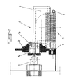
- the wire expressing device essentially consists of a comb 1 of guiding and expressing individual yarns from a web of yarns and by means 2 of compressed air blowing at the right of each interval between two teeth 3 of said comb 1, this air blowing means 2 cooperating with the comb 1 to produce expressing excess moisture.
- the comb 1 is preferably constituted by an assembly of teeth 3 and spacers 4 disposed between said teeth 3 and by at least one pin 5 for clamping said teeth 3 and spacers 4 on a support 6 ( Figures 1 and 2).
- Such a constitution of the comb 1 allows an easy adaptation thereof to a predetermined quantity of yarns of a sheet, by simple disassembly of the one or more pins 5 of the support 6 and mounting or dismounting the number of pairs of teeth and spacer required, then reassembly of the newly fitted pins 5 on the support 6.
- the teeth 3 are advantageously in the form of platelets thin, whose planar section greatly exceeds that of the spacers 4.
- Such a production of teeth 3 and spacers 4 allows precise guidance of each wire between two successive teeth 3 and the expression of humidity so independent from one wire to another, that is to say without said wires being able to enter contact before and during said expression.
- the spacers 4 which are interchangeable, have variable thicknesses depending on the metric number of the wires to be treated. So, depending on the metric number or the diameter of the wires, comb 1 is entirely disassembled and spacers 4 adapted to said metric number are mounted on the pins 5 between the plates forming the teeth 3, the assembly being tightened on the support 6. As a result, the threads of a sheet are always guided in a way optimal between teeth 3.
- the device is completed, in addition, by a cylinder 7 of diversion of the ply of wires extending, in the service position, at least partially below the level of the spacers 4 of the comb 1 (FIG. 1), so as to apply the threads of the tablecloth obliquely against the corresponding edge of the spacers 4.
- a cylinder 7 of diversion of the ply of wires extending, in the service position, at least partially below the level of the spacers 4 of the comb 1 (FIG. 1), so as to apply the threads of the tablecloth obliquely against the corresponding edge of the spacers 4.
- the spacers 4 advantageously have, seen from the entrance wires in the combs 1, a chamfer 8 or a rounding. So the threads of the tablecloth which are diverted by cylinder 7 are applied with pressure predetermined against the chamfer 8 or the rounding of the spacers 4 and, under the effect of the pressure resulting from the application by the cylinder 7 and from the traction on the wires, a significant mechanical expression of the humidity is obtained outside the wire.
- the air blowing means 2 is in the form of a nozzle 9 elongated, extending parallel above the comb 1 and delivering a flat jet to through a slot 10, said nozzle 9 being connected to an air supply means compressed via a connector 11.
- the air blowing means 2 can also be presented under form of a nozzle with parallel cylindrical jets, the air blowing holes of which have a diameter corresponding to that of the wires to be expressed.
- the nozzle 9 is advantageously pivotally mounted on the support 6 of the comb 1 by via a lever 12, the connection 11 of the supply means being under form of a tight rotary coupling, the axis of rotation of which is aligned with that of the lever 12.
- a lever 12 the connection 11 of the supply means being under form of a tight rotary coupling, the axis of rotation of which is aligned with that of the lever 12.
- the cylinder diversion 7 is also mounted on a pivoting lever 13, the axis of which pivot is aligned with that of the lever 12 for supporting the nozzle 9.
- the lever 12 for supporting the nozzle 9 and the lever 13 for supporting the diversion cylinder 7 are preferably mounted on a bearing of common pivot 14 ( Figure 1).
- the plates forming the teeth 3 of the comb 1 have, on their side facing the nozzle 9, in position service of the latter, a cutout 15 corresponding substantially to the section of said nozzle 9 (FIG. 1).
- the nozzle 9 can be tilted in position service at a distance from the spacers 4 of the comb 1 very small and limited by the cutting 15 of the plates forming the teeth 3.
- the nozzle 9 is mounted on its support lever pivotable 12 in an adjustable manner in rotation about its longitudinal axis, with possibility of locking in position by means of a screw 16 cooperating with an oblong groove 17 passing through a flange 18 secured to the end nozzle 9.
- the blowing slot 10 of the nozzle 9 can be adjusted in the direction of the chamfer or rounded 8, optimally, by simple rotation of the nozzle 9, then locking in position thereof by tightening the flange 18 on lever 12 by means of screw 16.
- the section of the blowing slot 10 can be mechanically adjustable by providing movable edges in spacing, by means screws, in particular by oblique displacement relative to the blowing axis, or again by mounting the edges of the slot on removable shims.
- Such an adjustment of the cross section of the blowing slot 10 can be particularly interesting for influencing the speed of the air flow blowing, at constant pressure and flow, and thus on the transport capacity optimal air humidity.
- FIG. 3 of the accompanying drawings partially and more large scale an alternative embodiment of the comb 1 in which the teeth 3 are of two types, 3 '- 3 ", with different heights and arranged in sandwich course.
- a tooth more high 3 ' is always preceded and followed by a lower tooth 3 ", so that the spacing between the corresponding faces of two taller teeth 3 'is enlarged and that for the placement of two wires between these two teeth more high 3 'and lower intermediate tooth 3 ", just press the first wire against the internal face of the first highest tooth 3 'and to lower it between this tooth 3 'and the lower tooth 3 "until contact with the spacer 4, while the other wire can be pressed against the corresponding internal face of the second higher tooth 3 ", then be lowered in contact with the spacer 4 between the tooth lower 3 "and the higher tooth 3 '.
- an installation without risk of error, especially wire reversal is greatly facilitated.
- the levers 12 and 13 can be actuated so as to bring the nozzle 9 and the cylinder diversion 7 in the service position shown in Figure 1 of the drawings appended, and a continuous printing operation can be started simultaneously with the pressurized air supply to nozzle 9.
- All wires passing through the device according to the invention undergo a detour applying them on the corresponding spacers 4 and having the effect of producing an expression mechanical residual moisture, additional expression by air jet under pressure being produced by pressurized air blown through slot 10 of the nozzle 9 on the front part of the spacers 4, the air thus blown further providing the transport and evacuation of the humidity thus expressed out of the comb 1 in the space under the latter and under its support 6.
Landscapes
- Engineering & Computer Science (AREA)
- Textile Engineering (AREA)
- Mechanical Engineering (AREA)
- General Engineering & Computer Science (AREA)
- Treatment Of Fiber Materials (AREA)
- Preliminary Treatment Of Fibers (AREA)
Claims (15)
- Vorrichtung zum Ausdrücken der Fäden einer Garnlage, dadurch gekennzeichnet, daß sie im wesentlichen aus einem Kamm (1) zum Führen und Ausdrücken der einzelnen Fäden einer Garnlage und aus einer Druckluft-Blasvorrichtung (2) im rechten Winkel zu jedem Zwischenraum zwischen zwei Zähnen (3) des Kammes (1) besteht, wobei die Luft-Blasvorrichtung (2) mit dem Kamm (1) zusammenwirkt, um das Ausdrücken des Feuchtigkeitsüberschusses zu verwirklichen.
- Vorrichtung nach Anspruch 1, dadurch gekennzeichnet, daß der Kamm (1) aus einer Zusammenfügung von Zähnen (3) und zwischen diesen Zähnen (3) angeordneten Zwischenstegen (4) und zumindest einem Dorn (5) zum Festspannen der Zähne (3) und Zwischenstege (4) auf einem Träger (6) besteht.
- Vorrichtung nach einem der Ansprüche 1 und 2, dadurch gekennzeichnet, daß die Zähne (3) in Form von dünnen Plättchen ausgebildet sind, deren Flächenschnitt weit über den der Zwischenstege (4) hinausreicht.
- Vorrichtung nach einem der Ansprüche 2 und 3, dadurch gekennzeichnet, daß die Zwischenstege (4) austauschbar sind und abhängig von der metrischen Nummer der zu behandelnden Fäden variable Dicken aufweisen.
- Vorrichtung nach einem der Ansprüche 1 bis 4, dadurch gekennzeichnet, daß die Vorrichtung außerdem durch einen Zylinder (7) zur Verlagerung der Garnlagen ergänzt ist, der sich in Betriebsstellung zumindest teilweise derart unter die Horizontalebene der Zwischenstege (4) des Kammes (1) erstreckt, daß die Fäden der Garnlage quer zu der entsprechenden Kante der Zwischenstege (4) angelegt werden.
- Vorrichtung nach einem der Ansprüche 2 bis 5, dadurch gekennzeichnet, daß die Zwischenstege (4), vom Eintritt der Fäden in den Kamm (1) aus gesehen, eine Seitenfase (8) oder Rundung aufweisen.
- Vorrichtung nach Anspruch 1, dadurch gekennzeichnet, daß die Luft-Blasvorrichtung (2) in Form einer langgestreckten Düse (9) ausgebildet ist, die sich parallel über dem Kamm (1) erstreckt und einen flachen Strahl quer über einen Schlitz (10) liefert, wobei die Düse (9) unter Zwischenschaltung eines Verbindungselementes (11) mit einer Druckluft-Beschickungseinrichtung verbunden ist.
- Vorrichtung nach Anspruch 1, dadurch gekennzeichnet, daß die Luft-Blasvorrichtung (2) in Form einer Parallel-Zylinderstrahldüse ausgebildet ist, deren Luftblaslöcher einen Durchmesser entsprechend demjenigen der auszudrückenden Fäden aufweisen.
- Vorrichtung nach einem der Ansprüche 7 und 8, dadurch gekennzeichnet, daß die Düse (9) unter Zwischenschaltung eines Hebels (12) schwenkbar auf dem Träger (6) des Kammes (1) befestigt ist, wobei das Verbindungselement (11) der Beschickungseinrichtung als dichte Drehverbindung ausgebildet ist, deren Rotationsachse mit derjenigen des Hebels (12) ausgerichtet ist.
- Vorrichtung nach einem der Ansprüche 5 und 9, dadurch gekennzeichnet, daß der Verlagerungszylinder (7) auf einem Schwenkhebel (13) befestigt ist, dessen Schwenkachse mit derjenigen des Traghebels (12) der Düse (9) ausgerichtet ist.
- Vorrichtung nach einem der Ansprüche 5, 9 und 10, dadurch gekennzeichnet, daß der Traghebel (12) der Düse (9) und der Traghebel (13) des Verlagerungszylinders (7) auf einem gemeinsamen Schwenklager gelagert sind.
- Vorrichtung nach einem der Ansprüche 1 bis 3 und 7 bis 11, dadurch gekennzeichnet, daß die die Zähne (3) des Kammes (1) bildenden Plättchen auf ihrer der Düse (9) in deren Betriebsstellung zugewandten Seite einen Zuschnitt (15) aufweisen, der genau dem Querschnitt der Düse (9) entspricht.
- Vorrichtung nach einem der Ansprüche 7 bis 12, dadurch gekennzeichnet, daß die Düse (9) auf ihrem schwenkbaren Traghebel (12) durch Drehen um ihre Längsachse einstellbar befestigt ist, mit der Möglichkeit einer Positionsverriegelung durch Zwischenschaltung einer Schraube (16), die mit einer länglichen Nut (17) zusammenwirkt, die quer über einen einstückig mit der entsprechenden Außenseite der Düse (9) verbundenen Flansch (18) verläuft.
- Vorrichtung nach Anspruch 7, dadurch gekennzeichnet, daß der Querschnitt des Blasschlitzes (10) der Düse (9) durch die Vorsehung von Randkanten mechanisch einstellbar ist, deren Abstand mittels Schrauben verstellbar ist, insbesondere durch Querverschiebung bezüglich der Blasachse oder auch durch Befestigung der Randkanten des Schlitzes auf herausziehbaren Unterlegkeilen.
- Vorrichtung nach einem der Ansprüche 1 bis 3, dadurch gekennzeichnet, daß der Kamm (1) zweierlei Arten (3', 3") von Zähnen (3) besitzt, die unterschiedliche Höhen aufweisen und abwechselnd angeordnet sind.
Applications Claiming Priority (2)
| Application Number | Priority Date | Filing Date | Title |
|---|---|---|---|
| FR9512194A FR2739878B1 (fr) | 1995-10-13 | 1995-10-13 | Dispositif d'exprimage sur fils |
| FR9512194 | 1995-10-13 |
Publications (2)
| Publication Number | Publication Date |
|---|---|
| EP0768420A1 EP0768420A1 (de) | 1997-04-16 |
| EP0768420B1 true EP0768420B1 (de) | 1999-05-26 |
Family
ID=9483627
Family Applications (1)
| Application Number | Title | Priority Date | Filing Date |
|---|---|---|---|
| EP96440082A Expired - Lifetime EP0768420B1 (de) | 1995-10-13 | 1996-10-09 | Quetschvorrichtung für Garne |
Country Status (7)
| Country | Link |
|---|---|
| US (1) | US5826348A (de) |
| EP (1) | EP0768420B1 (de) |
| JP (1) | JPH09111643A (de) |
| DE (1) | DE69602567T2 (de) |
| ES (1) | ES2134578T3 (de) |
| FR (1) | FR2739878B1 (de) |
| TR (1) | TR199600803A2 (de) |
Families Citing this family (1)
| Publication number | Priority date | Publication date | Assignee | Title |
|---|---|---|---|---|
| CN108774830A (zh) * | 2018-08-18 | 2018-11-09 | 张家港市凯利雅特种纺织纱线有限公司 | 一种用于氨纶纱线的传导染色装置 |
Family Cites Families (7)
| Publication number | Priority date | Publication date | Assignee | Title |
|---|---|---|---|---|
| US2005580A (en) * | 1934-09-07 | 1935-06-18 | B F Sturtevant Company Inc | Drying apparatus |
| GB621707A (en) * | 1944-03-07 | 1949-04-14 | Plexon Inc | Apparatus for drying coated threads and the like |
| DE1110124B (de) * | 1959-11-05 | 1961-07-06 | Schilde Maschb Ag | Trockner fuer Natur- und Kunstfaserkabel |
| DE2310878A1 (de) * | 1973-03-05 | 1974-09-12 | Burlington Industries Inc | Verfahren und vorrichtung zur behandlung von gesponnenem garn |
| IT1086929B (it) * | 1977-10-25 | 1985-05-31 | Snia Viscosa | Procedimento perfezionato e dispositivo per la filatura continua del rayon alla viscosa |
| DE3310878A1 (de) * | 1983-03-25 | 1984-09-27 | Hoechst Ag, 6230 Frankfurt | Optische antipoden von 8-amino-4-phenyl-1,2,3,4-tetrahydroisochinolin, verfahren zu ihrer herstellung und sie enthaltende arzneimittel mit antidepressiver wirkung |
| DD233870A1 (de) * | 1985-01-07 | 1986-03-12 | Textima Veb K | Verfahren und vorrichtung zum entfernen von fluessigkeiten aus laufenden endlosen faeden |
-
1995
- 1995-10-13 FR FR9512194A patent/FR2739878B1/fr not_active Expired - Fee Related
-
1996
- 1996-10-09 DE DE69602567T patent/DE69602567T2/de not_active Expired - Fee Related
- 1996-10-09 EP EP96440082A patent/EP0768420B1/de not_active Expired - Lifetime
- 1996-10-09 ES ES96440082T patent/ES2134578T3/es not_active Expired - Lifetime
- 1996-10-10 TR TR96/00803A patent/TR199600803A2/xx unknown
- 1996-10-10 US US08/728,798 patent/US5826348A/en not_active Expired - Lifetime
- 1996-10-11 JP JP8270173A patent/JPH09111643A/ja active Pending
Also Published As
| Publication number | Publication date |
|---|---|
| DE69602567D1 (de) | 1999-07-01 |
| US5826348A (en) | 1998-10-27 |
| TR199600803A2 (tr) | 1997-04-22 |
| JPH09111643A (ja) | 1997-04-28 |
| FR2739878A1 (fr) | 1997-04-18 |
| DE69602567T2 (de) | 2000-01-27 |
| EP0768420A1 (de) | 1997-04-16 |
| FR2739878B1 (fr) | 1997-12-05 |
| ES2134578T3 (es) | 1999-10-01 |
Similar Documents
| Publication | Publication Date | Title |
|---|---|---|
| FR2651254A1 (fr) | Procede et appareillage de filage en fausse torsion. | |
| FR2554137A1 (fr) | Cylindre secheur pour machine a matiere en bande, notamment a papier | |
| FR2626012A1 (fr) | Dispositif prevu sur une carde pour parfaire le nettoyage de la matiere fibreuse traitee | |
| EP0768420B1 (de) | Quetschvorrichtung für Garne | |
| FR2754279A1 (fr) | Procede de teinture a la continue de fils et files de fibres | |
| EP1016742B1 (de) | Montagevorrichtung einer zylindrischen Rundkamm-Reinigungsbürste mit automatischem Abnutzungsausgleich einer Kämmaschine | |
| FR2857985A1 (fr) | Machine pour le cablage / torsion et la fixation en continu de fils | |
| CH659488A5 (fr) | Procede et dispositif pour produire des fils guipes. | |
| CH678863A5 (de) | ||
| FR2480799A1 (fr) | Procede et dispositif pour la filature de fibres textiles liberees | |
| BE1008353A3 (fr) | Dispositif pour soumettre en continu des fibres en forme de fil a un traitement thermique par voie humide. | |
| EP0808929B1 (de) | Vorrichtung zur Führung und/oder Stützung von Garnen | |
| FR2583784A1 (fr) | Procede et dispositif pour l'obtention d'un fil de fibres comportant une ame de fibres discontinues, recouverte d'une gaine de fibres discontinues. | |
| FR2717505A1 (fr) | Dispositif pour sécher et encoller un fil textile en mouvement et machine comportant un tel dispositif. | |
| FR2748756A1 (fr) | Tete d'enduction de teinture par depot de bain sur fils en mouvement | |
| EP0253036B1 (de) | Verfahren und Vorrichtung zum Abziehen vom Gewebekantenabfall in Webmaschinen | |
| FR2476692A1 (fr) | Dispositif pour la fabrication de file a effets | |
| EP0943718B1 (de) | Vorrichtung zum Auftragen einer Farbflotte auf laufende Garne | |
| BE473746A (fr) | Perfectionnements a la fabrication de feutres, notamment en fibres de verre ou autres fibres minerales | |
| FR2635339A1 (fr) | Procede de filature du type a bouts liberes, et dispositif pour mettre en oeuvre ce procede | |
| FR2614632A1 (fr) | Machine de fabrication d'un fil de lin sans torsion | |
| FR2462494A1 (fr) | Appareil perfectionne pour le filage de fil par fibres liberees | |
| FR2652592A1 (fr) | Procede et appareillage de filage en fausse torsion. | |
| FR2767842A1 (fr) | Dispositif d'alimentation d'une nappe de matiere fibreuse, notamment de lin teille | |
| FR2566013A1 (fr) | Procede de traitement thermique ou chimique en continu d'un fil textile fin et machine pour la mise en oeuvre de ce procede |
Legal Events
| Date | Code | Title | Description |
|---|---|---|---|
| PUAI | Public reference made under article 153(3) epc to a published international application that has entered the european phase |
Free format text: ORIGINAL CODE: 0009012 |
|
| AK | Designated contracting states |
Kind code of ref document: A1 Designated state(s): CH DE ES GB IT LI |
|
| 17P | Request for examination filed |
Effective date: 19970613 |
|
| GRAG | Despatch of communication of intention to grant |
Free format text: ORIGINAL CODE: EPIDOS AGRA |
|
| 17Q | First examination report despatched |
Effective date: 19990202 |
|
| GRAG | Despatch of communication of intention to grant |
Free format text: ORIGINAL CODE: EPIDOS AGRA |
|
| GRAH | Despatch of communication of intention to grant a patent |
Free format text: ORIGINAL CODE: EPIDOS IGRA |
|
| GRAH | Despatch of communication of intention to grant a patent |
Free format text: ORIGINAL CODE: EPIDOS IGRA |
|
| GRAA | (expected) grant |
Free format text: ORIGINAL CODE: 0009210 |
|
| AK | Designated contracting states |
Kind code of ref document: B1 Designated state(s): CH DE ES GB IT LI |
|
| REG | Reference to a national code |
Ref country code: CH Ref legal event code: EP |
|
| REF | Corresponds to: |
Ref document number: 69602567 Country of ref document: DE Date of ref document: 19990701 |
|
| GBT | Gb: translation of ep patent filed (gb section 77(6)(a)/1977) |
Effective date: 19990714 |
|
| ITF | It: translation for a ep patent filed | ||
| REG | Reference to a national code |
Ref country code: ES Ref legal event code: FG2A Ref document number: 2134578 Country of ref document: ES Kind code of ref document: T3 |
|
| PLBE | No opposition filed within time limit |
Free format text: ORIGINAL CODE: 0009261 |
|
| STAA | Information on the status of an ep patent application or granted ep patent |
Free format text: STATUS: NO OPPOSITION FILED WITHIN TIME LIMIT |
|
| 26N | No opposition filed | ||
| PG25 | Lapsed in a contracting state [announced via postgrant information from national office to epo] |
Ref country code: LI Free format text: LAPSE BECAUSE OF NON-PAYMENT OF DUE FEES Effective date: 20001031 Ref country code: CH Free format text: LAPSE BECAUSE OF NON-PAYMENT OF DUE FEES Effective date: 20001031 |
|
| REG | Reference to a national code |
Ref country code: CH Ref legal event code: PL |
|
| REG | Reference to a national code |
Ref country code: GB Ref legal event code: IF02 |
|
| PGFP | Annual fee paid to national office [announced via postgrant information from national office to epo] |
Ref country code: DE Payment date: 20081010 Year of fee payment: 13 |
|
| PGFP | Annual fee paid to national office [announced via postgrant information from national office to epo] |
Ref country code: ES Payment date: 20081022 Year of fee payment: 13 |
|
| PGFP | Annual fee paid to national office [announced via postgrant information from national office to epo] |
Ref country code: IT Payment date: 20081018 Year of fee payment: 13 |
|
| PGFP | Annual fee paid to national office [announced via postgrant information from national office to epo] |
Ref country code: GB Payment date: 20081010 Year of fee payment: 13 |
|
| PG25 | Lapsed in a contracting state [announced via postgrant information from national office to epo] |
Ref country code: DE Free format text: LAPSE BECAUSE OF NON-PAYMENT OF DUE FEES Effective date: 20100501 |
|
| PG25 | Lapsed in a contracting state [announced via postgrant information from national office to epo] |
Ref country code: GB Free format text: LAPSE BECAUSE OF NON-PAYMENT OF DUE FEES Effective date: 20091009 |
|
| REG | Reference to a national code |
Ref country code: ES Ref legal event code: FD2A Effective date: 20110329 |
|
| PG25 | Lapsed in a contracting state [announced via postgrant information from national office to epo] |
Ref country code: IT Free format text: LAPSE BECAUSE OF NON-PAYMENT OF DUE FEES Effective date: 20091009 |
|
| PG25 | Lapsed in a contracting state [announced via postgrant information from national office to epo] |
Ref country code: ES Free format text: LAPSE BECAUSE OF NON-PAYMENT OF DUE FEES Effective date: 20110316 |
|
| PG25 | Lapsed in a contracting state [announced via postgrant information from national office to epo] |
Ref country code: ES Free format text: LAPSE BECAUSE OF NON-PAYMENT OF DUE FEES Effective date: 20091010 |