EP0768420B1 - Device for squeezing yarns - Google Patents
Device for squeezing yarns Download PDFInfo
- Publication number
- EP0768420B1 EP0768420B1 EP96440082A EP96440082A EP0768420B1 EP 0768420 B1 EP0768420 B1 EP 0768420B1 EP 96440082 A EP96440082 A EP 96440082A EP 96440082 A EP96440082 A EP 96440082A EP 0768420 B1 EP0768420 B1 EP 0768420B1
- Authority
- EP
- European Patent Office
- Prior art keywords
- nozzle
- comb
- teeth
- spacers
- lever
- Prior art date
- Legal status (The legal status is an assumption and is not a legal conclusion. Google has not performed a legal analysis and makes no representation as to the accuracy of the status listed.)
- Expired - Lifetime
Links
- 125000006850 spacer group Chemical group 0.000 claims description 26
- 238000007664 blowing Methods 0.000 claims description 19
- 238000011282 treatment Methods 0.000 description 5
- 230000000694 effects Effects 0.000 description 4
- 238000009987 spinning Methods 0.000 description 3
- 238000010981 drying operation Methods 0.000 description 2
- 238000004519 manufacturing process Methods 0.000 description 2
- 238000000034 method Methods 0.000 description 2
- 239000004753 textile Substances 0.000 description 2
- 238000005406 washing Methods 0.000 description 2
- 230000006978 adaptation Effects 0.000 description 1
- 238000004061 bleaching Methods 0.000 description 1
- 210000001520 comb Anatomy 0.000 description 1
- 230000008878 coupling Effects 0.000 description 1
- 238000010168 coupling process Methods 0.000 description 1
- 238000005859 coupling reaction Methods 0.000 description 1
- 238000005520 cutting process Methods 0.000 description 1
- 238000006073 displacement reaction Methods 0.000 description 1
- 238000001035 drying Methods 0.000 description 1
- 238000004043 dyeing Methods 0.000 description 1
- 238000001704 evaporation Methods 0.000 description 1
- 230000008020 evaporation Effects 0.000 description 1
- 238000009434 installation Methods 0.000 description 1
- 238000012986 modification Methods 0.000 description 1
- 230000004048 modification Effects 0.000 description 1
- 238000006467 substitution reaction Methods 0.000 description 1
- 238000009941 weaving Methods 0.000 description 1
Images

Classifications
-
- D—TEXTILES; PAPER
- D06—TREATMENT OF TEXTILES OR THE LIKE; LAUNDERING; FLEXIBLE MATERIALS NOT OTHERWISE PROVIDED FOR
- D06B—TREATING TEXTILE MATERIALS USING LIQUIDS, GASES OR VAPOURS
- D06B15/00—Removing liquids, gases or vapours from textile materials in association with treatment of the materials by liquids, gases or vapours
- D06B15/09—Removing liquids, gases or vapours from textile materials in association with treatment of the materials by liquids, gases or vapours by jets of gases
-
- F—MECHANICAL ENGINEERING; LIGHTING; HEATING; WEAPONS; BLASTING
- F26—DRYING
- F26B—DRYING SOLID MATERIALS OR OBJECTS BY REMOVING LIQUID THEREFROM
- F26B13/00—Machines and apparatus for drying fabrics, fibres, yarns, or other materials in long lengths, with progressive movement
- F26B13/24—Arrangements of devices using drying processes not involving heating
- F26B13/28—Arrangements of devices using drying processes not involving heating for applying pressure; for brushing; for wiping
Definitions
- the present invention relates to the field of the textile industry, in particularly the treatment by washing and / or dyeing of the threads and has for object wire expressing device.
- Textile threads generally undergo, before their use, especially for weaving, washing and / or bleaching treatments as well than dye. These various treatments are carried out wet, having as a consequence an excess of humidity of the order of 100% to 150% by weight, and require a subsequent drying operation.
- the object of the present invention is to overcome the drawbacks of the expression devices known to date by providing an expression device on threads suitable for treating a sheet of threads, allowing optimal expression of each ply yarn and easy placement of the ply yarns in said device.
- the device for expressing the threads of a layer of threads is characterized in that it consists essentially of a comb for guiding and expressing the wires individual plies of yarn and by means of blowing compressed air to the right of each interval between two teeth of said comb, this blowing means air cooperating with the comb to express the excess moisture.
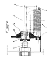
- the wire expressing device essentially consists of a comb 1 of guiding and expressing individual yarns from a web of yarns and by means 2 of compressed air blowing at the right of each interval between two teeth 3 of said comb 1, this air blowing means 2 cooperating with the comb 1 to produce expressing excess moisture.
- the comb 1 is preferably constituted by an assembly of teeth 3 and spacers 4 disposed between said teeth 3 and by at least one pin 5 for clamping said teeth 3 and spacers 4 on a support 6 ( Figures 1 and 2).
- Such a constitution of the comb 1 allows an easy adaptation thereof to a predetermined quantity of yarns of a sheet, by simple disassembly of the one or more pins 5 of the support 6 and mounting or dismounting the number of pairs of teeth and spacer required, then reassembly of the newly fitted pins 5 on the support 6.
- the teeth 3 are advantageously in the form of platelets thin, whose planar section greatly exceeds that of the spacers 4.
- Such a production of teeth 3 and spacers 4 allows precise guidance of each wire between two successive teeth 3 and the expression of humidity so independent from one wire to another, that is to say without said wires being able to enter contact before and during said expression.
- the spacers 4 which are interchangeable, have variable thicknesses depending on the metric number of the wires to be treated. So, depending on the metric number or the diameter of the wires, comb 1 is entirely disassembled and spacers 4 adapted to said metric number are mounted on the pins 5 between the plates forming the teeth 3, the assembly being tightened on the support 6. As a result, the threads of a sheet are always guided in a way optimal between teeth 3.
- the device is completed, in addition, by a cylinder 7 of diversion of the ply of wires extending, in the service position, at least partially below the level of the spacers 4 of the comb 1 (FIG. 1), so as to apply the threads of the tablecloth obliquely against the corresponding edge of the spacers 4.
- a cylinder 7 of diversion of the ply of wires extending, in the service position, at least partially below the level of the spacers 4 of the comb 1 (FIG. 1), so as to apply the threads of the tablecloth obliquely against the corresponding edge of the spacers 4.
- the spacers 4 advantageously have, seen from the entrance wires in the combs 1, a chamfer 8 or a rounding. So the threads of the tablecloth which are diverted by cylinder 7 are applied with pressure predetermined against the chamfer 8 or the rounding of the spacers 4 and, under the effect of the pressure resulting from the application by the cylinder 7 and from the traction on the wires, a significant mechanical expression of the humidity is obtained outside the wire.
- the air blowing means 2 is in the form of a nozzle 9 elongated, extending parallel above the comb 1 and delivering a flat jet to through a slot 10, said nozzle 9 being connected to an air supply means compressed via a connector 11.
- the air blowing means 2 can also be presented under form of a nozzle with parallel cylindrical jets, the air blowing holes of which have a diameter corresponding to that of the wires to be expressed.
- the nozzle 9 is advantageously pivotally mounted on the support 6 of the comb 1 by via a lever 12, the connection 11 of the supply means being under form of a tight rotary coupling, the axis of rotation of which is aligned with that of the lever 12.
- a lever 12 the connection 11 of the supply means being under form of a tight rotary coupling, the axis of rotation of which is aligned with that of the lever 12.
- the cylinder diversion 7 is also mounted on a pivoting lever 13, the axis of which pivot is aligned with that of the lever 12 for supporting the nozzle 9.
- the lever 12 for supporting the nozzle 9 and the lever 13 for supporting the diversion cylinder 7 are preferably mounted on a bearing of common pivot 14 ( Figure 1).
- the plates forming the teeth 3 of the comb 1 have, on their side facing the nozzle 9, in position service of the latter, a cutout 15 corresponding substantially to the section of said nozzle 9 (FIG. 1).
- the nozzle 9 can be tilted in position service at a distance from the spacers 4 of the comb 1 very small and limited by the cutting 15 of the plates forming the teeth 3.
- the nozzle 9 is mounted on its support lever pivotable 12 in an adjustable manner in rotation about its longitudinal axis, with possibility of locking in position by means of a screw 16 cooperating with an oblong groove 17 passing through a flange 18 secured to the end nozzle 9.
- the blowing slot 10 of the nozzle 9 can be adjusted in the direction of the chamfer or rounded 8, optimally, by simple rotation of the nozzle 9, then locking in position thereof by tightening the flange 18 on lever 12 by means of screw 16.
- the section of the blowing slot 10 can be mechanically adjustable by providing movable edges in spacing, by means screws, in particular by oblique displacement relative to the blowing axis, or again by mounting the edges of the slot on removable shims.
- Such an adjustment of the cross section of the blowing slot 10 can be particularly interesting for influencing the speed of the air flow blowing, at constant pressure and flow, and thus on the transport capacity optimal air humidity.
- FIG. 3 of the accompanying drawings partially and more large scale an alternative embodiment of the comb 1 in which the teeth 3 are of two types, 3 '- 3 ", with different heights and arranged in sandwich course.
- a tooth more high 3 ' is always preceded and followed by a lower tooth 3 ", so that the spacing between the corresponding faces of two taller teeth 3 'is enlarged and that for the placement of two wires between these two teeth more high 3 'and lower intermediate tooth 3 ", just press the first wire against the internal face of the first highest tooth 3 'and to lower it between this tooth 3 'and the lower tooth 3 "until contact with the spacer 4, while the other wire can be pressed against the corresponding internal face of the second higher tooth 3 ", then be lowered in contact with the spacer 4 between the tooth lower 3 "and the higher tooth 3 '.
- an installation without risk of error, especially wire reversal is greatly facilitated.
- the levers 12 and 13 can be actuated so as to bring the nozzle 9 and the cylinder diversion 7 in the service position shown in Figure 1 of the drawings appended, and a continuous printing operation can be started simultaneously with the pressurized air supply to nozzle 9.
- All wires passing through the device according to the invention undergo a detour applying them on the corresponding spacers 4 and having the effect of producing an expression mechanical residual moisture, additional expression by air jet under pressure being produced by pressurized air blown through slot 10 of the nozzle 9 on the front part of the spacers 4, the air thus blown further providing the transport and evacuation of the humidity thus expressed out of the comb 1 in the space under the latter and under its support 6.
Landscapes
- Engineering & Computer Science (AREA)
- Textile Engineering (AREA)
- Mechanical Engineering (AREA)
- General Engineering & Computer Science (AREA)
- Treatment Of Fiber Materials (AREA)
- Preliminary Treatment Of Fibers (AREA)
Description
La présente invention concerne le domaine de l'industrie textile, en particulier le traitement par lavage et/ou par teinture des fils et a pour objet un dispositif d'exprimage sur fils.The present invention relates to the field of the textile industry, in particularly the treatment by washing and / or dyeing of the threads and has for object wire expressing device.
Les fils textiles subissent généralement, avant leur utilisation, notamment pour le tissage, des traitements de lavage et/ou de blanchissage ainsi que de teinture. Ces différents traitements sont effectués par voie humide, ayant pour conséquence un excédent d'humidité de l'ordre de 100 % à 150 % en poids, et nécessitent une opération de séchage consécutive.Textile threads generally undergo, before their use, especially for weaving, washing and / or bleaching treatments as well than dye. These various treatments are carried out wet, having as a consequence an excess of humidity of the order of 100% to 150% by weight, and require a subsequent drying operation.
Actuellement, l'opération de séchage est réalisée par apport d'énergie sous forme de chaleur et/ou d'un courant d'air réalisant une évaporation de l'excédent d'humidité. Un tel séchage entraíne une consommation très élevée d'énergie et, de ce fait, un coût de production élevé.Currently, the drying operation is carried out using energy in the form of heat and / or a stream of air evaporation of excess moisture. Such drying results in very high consumption energy and therefore a high production cost.
Il est également connu de réaliser un essorage mécanique, notamment d'écheveaux ou de bobines, au moyen de dispositifs centrifuges. Dans un tel cas, une humidité résiduelle de 50 % peut être obtenue très rapidement avec une dépense énergétique très faible. Cependant, ces procédés d'essorage ne sont pas exploitables dans le cadre d'un traitement en continu de fils, c'est-à-dire lorsque les fils sont en défilement et sont disposés en nappes.It is also known to carry out a mechanical spin, in particular hanks or coils, by means of centrifugal devices. In in such a case, a residual humidity of 50% can be obtained very quickly with very low energy expenditure. However, these spinning processes are not not usable in the context of continuous wire processing, i.e. when the threads are running and are arranged in layers.
Enfin, on connaít également un procédé d'exprimage de l'excédent d'humidité par une surpression d'air voir par exemple GB-A-2009030 et FR-A-2575770. Un tel exprimage permet des gains comparables à ceux obtenus par essorage mécanique. Cependant, dans le cas du traitement de fils en nappes, un tel procédé d'exprimage n'est pas adapté, les fils n'étant pas soutenus lors du traitement par jet d'air et risquant d'être emmêlés sous l'effet dudit jet.Finally, we also know a process for expressing the surplus humidity by an air overpressure see for example GB-A-2009030 and FR-A-2575770. Such an expression allows gains comparable to those obtained by mechanical spinning. However, in the case of treatment of ply yarns, such an expressing method is not suitable, the yarns are not supported during the air jet treatment and may be tangled under the effect of said throw.
La présente invention a pour but de pallier les inconvénients des dispositifs d'exprimage connus à ce jour en proposant un dispositif d'exprimage sur fils adapté au traitement d'une nappe de fils, permettant un exprimage optimal de chaque fil de la nappe et une mise en place aisée des fils de la nappe dans ledit dispositif.The object of the present invention is to overcome the drawbacks of the expression devices known to date by providing an expression device on threads suitable for treating a sheet of threads, allowing optimal expression of each ply yarn and easy placement of the ply yarns in said device.
A cet effet, le dispositif d'exprimage des fils d'une nappe de fils est caractérisé en ce qu'il est essentiellement constitué par un peigne de guidage et d'exprimage des fils individuels d'une nappe de fils et par un moyen de soufflage d'air comprimé au droit de chaque intervalle entre deux dents dudit peigne, ce moyen de soufflage d'air coopérant avec le peigne pour réaliser l'exprimage de l'excédent d'humidité. To this end, the device for expressing the threads of a layer of threads is characterized in that it consists essentially of a comb for guiding and expressing the wires individual plies of yarn and by means of blowing compressed air to the right of each interval between two teeth of said comb, this blowing means air cooperating with the comb to express the excess moisture.
L'invention sera mieux comprise, grâce à la description ci-après, qui
se rapporte à un mode de réalisation préféré, donné à titre d'exemple non limitatif,
et expliqué avec référence aux dessins schématiques annexés, dans lesquels :
Conformément à l'invention, et comme le montrent plus
particulièrement, à titre d'exemple, les figures 1 et 2 des dessins annexés, le
dispositif d'exprimage sur fils est essentiellement constitué par un peigne 1 de
guidage et d'exprimage des fils individuels d'une nappe de fils et par un moyen 2
de soufflage d'air comprimé au droit de chaque intervalle entre deux dents 3 dudit
peigne 1, ce moyen de soufflage d'air 2 coopérant avec le peigne 1 pour réaliser
l'exprimage de l'excédent d'humidité.In accordance with the invention, and as shown more
particularly, by way of example, Figures 1 and 2 of the accompanying drawings, the
wire expressing device essentially consists of a
Le peigne 1 est préférentiellement constitué par un assemblage de
dents 3 et d'entretoises 4 disposées entre lesdites dents 3 et par au moins une
broche 5 de serrage desdites dents 3 et entretoises 4 sur un support 6 (figures 1
et 2). Une telle constitution du peigne 1 permet une adaptation aisée de celui-ci à
une quantité prédéterminée de fils d'une nappe, par simple démontage de la ou des
broches 5 du support 6 et montage ou démontage du nombre de paires de dent et
entretoise nécessaire, puis remontage des broches 5 nouvellement équipées sur le
support 6.The
Les dents 3 se présentent avantageusement sous forme de plaquettes
minces, dont la section plane dépasse largement celle des entretoises 4. Une telle
réalisation des dents 3 et des entretoises 4 permet un guidage précis de chaque fil
entre deux dents 3 successives et l'exprimage de l'humidité de manière
indépendante d'un fil à l'autre, c'est-à-dire sans que lesdits fils puissent entrer en
contact avant et pendant ledit exprimage.The
Les entretoises 4, qui sont interchangeables, présentent des
épaisseurs variables en fonction du numéro métrique des fils à traiter. Ainsi,
suivant le numéro métrique ou le diamètre des fils, le peigne 1 est entièrement
démonté et des entretoises 4 adaptées audit numéro métrique sont montées sur les
broches 5 entre les plaquettes formant les dents 3, l'ensemble étant serré sur le
support 6. Il en résulte que les fils d'une nappe sont toujours guidés d'une manière
optimale entre les dents 3. The
Le dispositif est complété, en outre, par un cylindre 7 de
détournement de la nappe de fils s'étendant, en position de service, au moins
partiellement sous le niveau des entretoises 4 du peigne 1 (figure 1), de manière à
appliquer les fils de la nappe obliquement contre l'arête correspondante des
entretoises 4. Ainsi, par l'effet de frottement des fils contre l'arête des entretoises 4
et, du fait de la tension de la nappe de fils en défilement, on obtient un exprimage
important d'humidité dû à un écrasement relatif des fils sur les entretoises 4.The device is completed, in addition, by a
Afin d'éviter une détérioration des fils lors de l'opération
d'exprimage, les entretoises 4 présentent avantageusement, vues à partir de l'entrée
des fils dans le peignes 1, un chanfrein 8 ou un arrondi. Ainsi, les fils de la nappe
qui sont détournés par le cylindre 7 sont appliqués avec une pression
prédéterminée contre le chanfrein 8 ou l'arrondi des entretoises 4 et, sous l'effet de
la pression résultant de l'application par le cylindre 7 et de la traction sur les fils,
on obtient un exprimage mécanique important de l'humidité hors du fil.To avoid damage to the wires during the operation
Expression, the
Le moyen de soufflage d'air 2 se présente sous forme d'une buse 9
allongée, s'étendant parallèlement au-dessus du peigne 1 et délivrant un jet plat à
travers une fente 10, ladite buse 9 étant raccordée à un moyen d'alimentation en air
comprimé par l'intermédiaire d'un raccord 11.The
Selon une variante de réalisation de l'invention, non représentée aux dessins annexés, le moyen de soufflage d'air 2 peut également se présenter sous forme d'une buse à jets cylindriques parallèles, dont les trous de soufflage d'air présentent un diamètre correspondant à celui des fils à exprimer.According to an alternative embodiment of the invention, not shown in attached drawings, the air blowing means 2 can also be presented under form of a nozzle with parallel cylindrical jets, the air blowing holes of which have a diameter corresponding to that of the wires to be expressed.
Selon une autre caractéristique de l'invention, la buse 9 est
avantageusement montée de manière pivotante sur le support 6 du peigne 1 par
l'intermédiaire d'un levier 12, le raccord 11 du moyen d'alimentation étant sous
forme d'un raccord tournant étanche, dont l'axe de rotation est aligné avec celui du
levier 12. Un tel mode de réalisation permet, comme le montre la figure 1 des
dessins annexés, en trait mixte fin, un pivotement du levier 12 avec la buse 9 hors
de sa zone de coopération avec le peigne 1, de manière à favoriser la mise en place
des fils entre les dents 3 du peigne 1.According to another characteristic of the invention, the
A cet effet, selon une autre caractéristique de l'invention, le cylindre
de détournement 7 est également monté sur un levier pivotant 13, dont l'axe de
pivotement est aligné avec celui du levier 12 de support de la buse 9.To this end, according to another characteristic of the invention, the
Le levier 12 de support de la buse 9 et le levier 13 de support du
cylindre de détournement 7 sont préférentiellement montés sur un palier de
pivotement commun 14 (figure 1). The
Selon une autre caractéristique de l'invention, les plaquettes formant
les dents 3 du peigne 1 présentent, sur leur côté tourné vers la buse 9, en position
de service de cette dernière, une découpe 15 correspondant sensiblement à la
section de ladite buse 9 (figure 1). Ainsi, la buse 9 peut être basculée en position
de service à une distance des entretoises 4 du peigne 1 très faible et limitée par la
découpe 15 des plaquettes formant les dents 3.According to another characteristic of the invention, the plates forming
the
Lorsque la buse 9 est ainsi en butée contre les dents 3, sa fente de
soufflage 10 se trouve à très faible distance au-dessus des fils de la nappe de fils
dont l'exprimage doit être réalisé et délivre un jet d'air en direction de l'entrée des
fils dans les dents 3 du peigne 1 et propulse l'humidité présente dans ces derniers
et/ou déjà partiellement exprimée sur le chanfrein 8 ou arrondi des entretoises 4, à
travers les dents 3 dans l'espace situé sous le support 6.When the
Selon une caractéristique de l'invention, et comme le montre la
figure 1 des dessins annexés, la buse 9 est montée sur son levier de support
pivotable 12 de manière réglable en rotation autour de son axe longitudinal, avec
possibilité de blocage en position par l'intermédiaire d'une vis 16 coopérant avec
une rainure oblongue 17 traversant un flasque 18 solidaire de l'extrémité
correspondante de la buse 9. Ainsi, la fente de soufflage 10 de la buse 9 peut être
réglée en direction du chanfrein ou arrondi 8, de manière optimale, par simple
rotation de la buse 9, puis blocage en position de celle-ci par serrage du flasque 18
sur le levier 12 au moyen de la vis 16.According to a characteristic of the invention, and as shown in the
Figure 1 of the accompanying drawings, the
Conformément à une autre caractéristique de l'invention, non
représentée aux dessins annexés, la section de la fente de soufflage 10 peut être
réglable mécaniquement par prévision de bords mobiles en écartement, au moyen
de vis, notamment par déplacement oblique par rapport à l'axe de soufflage, ou
encore par montage des bords de la fente sur des cales amovibles.According to another characteristic of the invention, not
shown in the accompanying drawings, the section of the blowing
Un tel réglage de la section de la fente de soufflage 10 peut être
particulièrement intéressant pour influer sur la vitesse du courant d'air de
soufflage, à pression et à débit constants, et ainsi sur la capacité de transport
optimal d'humidité par l'air.Such an adjustment of the cross section of the blowing
La figure 3 des dessins annexés représente partiellement et à plus
grande échelle une variante de réalisation du peigne 1 dans laquelle les dents 3
sont de deux types, 3' - 3", présentant des hauteurs différentes et disposées en
alternance.Figure 3 of the accompanying drawings partially and more
large scale an alternative embodiment of the
Comme il ressort plus particulièrement de la figure 3, une dent plus
haute 3' est toujours précédée et suivie par une dent moins haute 3", de sorte que
l'espacement entre les faces correspondantes de deux dents plus hautes 3' est
agrandi et que pour la mise en place de deux fils entre ces deux dents plus
hautes 3' et la dent intermédiaire plus basse 3", il suffit d'appuyer le premier fil
contre la face interne de la première dent la plus haute 3' et de la descendre entre
cette dent 3' et la dent plus basse 3" jusqu'au contact de l'entretoise 4, tandis que
l'autre fil peut être plaqué contre la face interne correspondante de la deuxième
dent plus haute 3", puis être descendu en contact avec l'entretoise 4 entre la dent
plus basse 3" et la dent plus haute 3'. Ainsi, une mise en place sans risque d'erreur,
en particulier d'interversion de fil, est grandement facilitée.As can be seen more particularly from FIG. 3, a tooth more
high 3 'is always preceded and followed by a
Après mise en place de l'ensemble des fils sur le peigne 1, les
leviers 12 et 13 peuvent être actionnés de manière à amener la buse 9 et le cylindre
de détournement 7 en position de service représentée à la figure 1 des dessins
annexés, et une opération d'exprimage en continu peut être démarrée
simultanément à l'alimentation en air sous pression de la buse 9. Tous les fils
passant dans le dispositif conforme à l'invention subissent un détour les appliquant
sur les entretoises correspondantes 4 et ayant pour effet de réaliser un exprimage
mécanique de leur humidité résiduelle, un exprimage complémentaire par jet d'air
sous pression étant réalisé par l'air sous pression soufflé à travers la fente 10 de la
buse 9 sur la partie avant des entretoises 4, l'air ainsi soufflé réalisant en outre le
transport et l'évacuation de l'humidité ainsi exprimée hors du peigne 1 dans
l'espace sous ce dernier et sous son support 6.After placing all the wires on
Grâce à l'invention, il est possible de réaliser un exprimage important de l'humidité de fils lavés ou teints avec des gains comparables à ceux obtenus par essorage, ce sur des fils défilant en continu.Thanks to the invention, it is possible to achieve significant expression moisture from washed or dyed yarns with gains comparable to those obtained by spinning, on threads running continuously.
Bien entendu, l'invention n'est pas limitée au mode de réalisation décrit et représenté aux dessins annexés. Des modifications restent possibles, notamment du point de vue de la constitution des divers éléments ou par substitution d'équivalents techniques, sans sortir pour autant du domaine de protection de l'invention.Of course, the invention is not limited to the embodiment described and shown in the accompanying drawings. Modifications are still possible, in particular from the point of view of the constitution of the various elements or by substitution of technical equivalents, without departing from the scope of protection of the invention.
Claims (15)
- Device for squeezing the strands of a layer of yarn,
characterized in that
it consists essentially of a comb (1) for guiding and squeezing the individual strands of a layer of yarn, and means (2) for blowing compressed air along the line of each gap between two teeth (3) of the said comb (1), such that the said means (2) for blowing compressed air cooperate with the comb (1) to squeeze out excess moisture. - Device according to Claim 1,
characterized in that
the comb (1) consists of an assembly of teeth (3) with spacers (4) arranged between the said teeth (3), and at least one pin-bolt (5) which holds the said teeth (3) and spacers (4) tightly onto a support (6). - Device according to either of Claims 1 or 2,
characterized in that
the teeth (3) are in the form of thin plates whose flat cross-sectional area is much larger than that of the spacers (4). - Device according to either of Claims 2 or 3,
characterized in that
the spacers (4) are interchangeable and can have various thicknesses, depending on the diameter of the strands to be treated. - Device according to any of Claims 1 to 4,
characterized in that
the device also comprises a deflection cylinder (7) for the layer of yarn, which in its working position extends at least partially under the level of the spacers (4) of the comb (1) so that the strands of the said layer encounter the corresponding edge of the spacers (4) obliquely. - Device according to any of Claims 2 to 5,
characterized in that
when seen from the direction in which the strands enter the comb (1), the spacers (4) are chamfered or rounded (8). - Device according to Claim 1,
characterized in that
the means (2) for blowing air are in the form of an elongated nozzle (9) extending parallel to and above the comb (1), which delivers a flat jet through a slit (10), the said nozzle (9) being connected to a means for supplying compressed air via a connector (11). - Device according to Claim 1,
characterized in that
the means (2) for blowing air are in the form of a nozzle with parallel cylindrical jets, whose air outlet holes have the same diameter as that of the strands to be squeezed. - Device according to either of Claims 7 or 8,
characterized in that
the nozzle (9) is mounted so that it pivots on the support (6) of the comb (1) via a lever (12), and the connector (11) of the means for supplying air is in the form of an airtight rotating connector whose rotation axis is aligned with the axis of the lever (12). - Device according to either of Claims 5 or 9,
characterized in that
the deflection cylinder (7) is mounted on a pivoting lever (13) whose pivoting axis is aligned with the pivoting axis of the lever (12) supporting the nozzle (9). - Device according to any of Claims 5, 9 and 10,
characterized in that
the lever (12) supporting the nozzle (9) and the lever (13) supporting the deflection cylinder (7) are mounted on a common pivot bearing (14). - Device according to any of Claims 1 to 3 and 7 to 11,
characterized in that
the plates forming the teeth (3) of the comb (1) comprise, on the side facing the nozzle (9) when the latter is in its working position, a cutout (15) corresponding essentially to the cross-section of the said nozzle (9). - Device according to any of Claims 7 to 12,
characterized in that
the nozzle (9) is mounted on its pivoting support lever (12) in a rotationally adjustable way around its longitudinal axis, and can be locked in position by a screw (16) which cooperates with an oblong groove (17) which crosses a plate (18) attached to the corresponding end of the nozzle (9). - Device according to Claim 7,
characterized in that
the area of the blowing slit (10) of the nozzle (9) can be mechanically adjusted by providing edges which can be moved together or apart by means of screws, notable by moving obliquely relative to the blowing axis, or even by mounting the edges of the slit on movable support blocks. - Device according to any of Claims 1 to 3,
characterized in that
the teeth (3) of the comb (1) are of two types (3', 3") which have different heights, and which are arranged in alternation.
Applications Claiming Priority (2)
| Application Number | Priority Date | Filing Date | Title |
|---|---|---|---|
| FR9512194 | 1995-10-13 | ||
| FR9512194A FR2739878B1 (en) | 1995-10-13 | 1995-10-13 | WIRE EXPRESSING DEVICE |
Publications (2)
| Publication Number | Publication Date |
|---|---|
| EP0768420A1 EP0768420A1 (en) | 1997-04-16 |
| EP0768420B1 true EP0768420B1 (en) | 1999-05-26 |
Family
ID=9483627
Family Applications (1)
| Application Number | Title | Priority Date | Filing Date |
|---|---|---|---|
| EP96440082A Expired - Lifetime EP0768420B1 (en) | 1995-10-13 | 1996-10-09 | Device for squeezing yarns |
Country Status (7)
| Country | Link |
|---|---|
| US (1) | US5826348A (en) |
| EP (1) | EP0768420B1 (en) |
| JP (1) | JPH09111643A (en) |
| DE (1) | DE69602567T2 (en) |
| ES (1) | ES2134578T3 (en) |
| FR (1) | FR2739878B1 (en) |
| TR (1) | TR199600803A2 (en) |
Families Citing this family (1)
| Publication number | Priority date | Publication date | Assignee | Title |
|---|---|---|---|---|
| CN108774830A (en) * | 2018-08-18 | 2018-11-09 | 张家港市凯利雅特种纺织纱线有限公司 | A kind of conduction dyeing apparatus for spandex yarn |
Family Cites Families (7)
| Publication number | Priority date | Publication date | Assignee | Title |
|---|---|---|---|---|
| US2005580A (en) * | 1934-09-07 | 1935-06-18 | B F Sturtevant Company Inc | Drying apparatus |
| GB621707A (en) * | 1944-03-07 | 1949-04-14 | Plexon Inc | Apparatus for drying coated threads and the like |
| DE1110124B (en) * | 1959-11-05 | 1961-07-06 | Schilde Maschb Ag | Dryer for natural and synthetic fiber cables |
| DE2310878A1 (en) * | 1973-03-05 | 1974-09-12 | Burlington Industries Inc | Staple yarn dehairing - by sizing and compaction by grooved roller |
| IT1086929B (en) * | 1977-10-25 | 1985-05-31 | Snia Viscosa | IMPROVED PROCEDURE AND DEVICE FOR CONTINUOUS SPINNING OF RAYON TO VISCOSE |
| DE3310878A1 (en) * | 1983-03-25 | 1984-09-27 | Hoechst Ag, 6230 Frankfurt | OPTICAL ANTIPODES OF 8-AMINO-4-PHENYL-1,2,3,4-TETRAHYDROISOCHINOLINE, METHOD FOR THE PRODUCTION THEREOF AND MEDICINAL PRODUCTS CONTAINING ITS ANTIDEPRESSIVE EFFECT |
| DD233870A1 (en) * | 1985-01-07 | 1986-03-12 | Textima Veb K | METHOD AND DEVICE FOR REMOVING FLUIDS FROM RUNNING ENDLESS FAEDES |
-
1995
- 1995-10-13 FR FR9512194A patent/FR2739878B1/en not_active Expired - Fee Related
-
1996
- 1996-10-09 EP EP96440082A patent/EP0768420B1/en not_active Expired - Lifetime
- 1996-10-09 ES ES96440082T patent/ES2134578T3/en not_active Expired - Lifetime
- 1996-10-09 DE DE69602567T patent/DE69602567T2/en not_active Expired - Fee Related
- 1996-10-10 US US08/728,798 patent/US5826348A/en not_active Expired - Lifetime
- 1996-10-10 TR TR96/00803A patent/TR199600803A2/en unknown
- 1996-10-11 JP JP8270173A patent/JPH09111643A/en active Pending
Also Published As
| Publication number | Publication date |
|---|---|
| FR2739878A1 (en) | 1997-04-18 |
| DE69602567D1 (en) | 1999-07-01 |
| JPH09111643A (en) | 1997-04-28 |
| TR199600803A2 (en) | 1997-04-22 |
| FR2739878B1 (en) | 1997-12-05 |
| US5826348A (en) | 1998-10-27 |
| EP0768420A1 (en) | 1997-04-16 |
| DE69602567T2 (en) | 2000-01-27 |
| ES2134578T3 (en) | 1999-10-01 |
Similar Documents
| Publication | Publication Date | Title |
|---|---|---|
| FR2651254A1 (en) | FALSE TORSION WIRING METHOD AND APPARATUS. | |
| EP0252572A1 (en) | Drying cylinder for web materials in particular for paper, and his remote control | |
| EP0768420B1 (en) | Device for squeezing yarns | |
| FR2499044A1 (en) | VOLTAGE-FREE WIRE SUPPLY METHOD AND APPARATUS AND APPARATUS FOR MANUFACTURING INFLATABLE WIRE | |
| FR2754279A1 (en) | CONTINUOUS YARN AND FIBER YARN DYING PROCESS | |
| EP1016742B1 (en) | Mounting apparatus of a cylindrical cleaning brush with automatic wear compensation for a cylindrical comb of a rectilinear comber | |
| FR2857985A1 (en) | Textile yarn continuous twisting and fixing machine has one or more treatment posts incorporating twisting, thermofixing, cooling and winding operations | |
| CH659488A5 (en) | METHOD AND DEVICE FOR PRODUCING GUIPED YARNS. | |
| CH678863A5 (en) | ||
| FR2480799A1 (en) | Direct spinning of textile fibres without rotor - using offset surfaces moving in the same direction | |
| BE1008353A3 (en) | Device for submit continuous fibre wire form for a heat treatment wet. | |
| EP0808929B1 (en) | Device for guiding and/or supporting yarns | |
| EP1470274A1 (en) | Device for cabling and continuous fixing of wires followed by complementary heat treatment | |
| FR2583784A1 (en) | Process and apparatus for obtaining a fibre yarn comprising a core of discontinuous fibres covered with a sheath of discontinuous fibres | |
| FR2717505A1 (en) | Yarn drying assembly | |
| FR2748756A1 (en) | Yarn dyeing head | |
| EP0253036B1 (en) | Process and apparatus to draw off waste selvedge in looms | |
| FR2476692A1 (en) | DEVICE FOR THE PRODUCTION OF EFFECT YARN | |
| EP0943718B1 (en) | Dye applicator for applying dye to moving yarns | |
| BE473746A (en) | IMPROVEMENTS IN THE MANUFACTURING OF FELTS, IN PARTICULAR IN GLASS FIBERS OR OTHER MINERAL FIBERS | |
| FR2635339A1 (en) | FREE SPINNING TYPE SPINNING PROCESS, AND DEVICE FOR CARRYING OUT SAID METHOD | |
| FR2614632A1 (en) | MACHINE FOR MANUFACTURING LINEN WITHOUT TORSION | |
| FR2462494A1 (en) | Fibre transfer device for open=end spinning appts. - which deposits fibres parallel to the yarn doffing direction | |
| FR2652592A1 (en) | FALSE TORSION WIRING METHOD AND APPARATUS. | |
| FR2566013A1 (en) | Process for the continuous thermal or chemical treatment of a fine textile yarn and machine for carrying out this process |
Legal Events
| Date | Code | Title | Description |
|---|---|---|---|
| PUAI | Public reference made under article 153(3) epc to a published international application that has entered the european phase |
Free format text: ORIGINAL CODE: 0009012 |
|
| AK | Designated contracting states |
Kind code of ref document: A1 Designated state(s): CH DE ES GB IT LI |
|
| 17P | Request for examination filed |
Effective date: 19970613 |
|
| GRAG | Despatch of communication of intention to grant |
Free format text: ORIGINAL CODE: EPIDOS AGRA |
|
| 17Q | First examination report despatched |
Effective date: 19990202 |
|
| GRAG | Despatch of communication of intention to grant |
Free format text: ORIGINAL CODE: EPIDOS AGRA |
|
| GRAH | Despatch of communication of intention to grant a patent |
Free format text: ORIGINAL CODE: EPIDOS IGRA |
|
| GRAH | Despatch of communication of intention to grant a patent |
Free format text: ORIGINAL CODE: EPIDOS IGRA |
|
| GRAA | (expected) grant |
Free format text: ORIGINAL CODE: 0009210 |
|
| AK | Designated contracting states |
Kind code of ref document: B1 Designated state(s): CH DE ES GB IT LI |
|
| REG | Reference to a national code |
Ref country code: CH Ref legal event code: EP |
|
| REF | Corresponds to: |
Ref document number: 69602567 Country of ref document: DE Date of ref document: 19990701 |
|
| GBT | Gb: translation of ep patent filed (gb section 77(6)(a)/1977) |
Effective date: 19990714 |
|
| ITF | It: translation for a ep patent filed | ||
| REG | Reference to a national code |
Ref country code: ES Ref legal event code: FG2A Ref document number: 2134578 Country of ref document: ES Kind code of ref document: T3 |
|
| PLBE | No opposition filed within time limit |
Free format text: ORIGINAL CODE: 0009261 |
|
| STAA | Information on the status of an ep patent application or granted ep patent |
Free format text: STATUS: NO OPPOSITION FILED WITHIN TIME LIMIT |
|
| 26N | No opposition filed | ||
| PG25 | Lapsed in a contracting state [announced via postgrant information from national office to epo] |
Ref country code: LI Free format text: LAPSE BECAUSE OF NON-PAYMENT OF DUE FEES Effective date: 20001031 Ref country code: CH Free format text: LAPSE BECAUSE OF NON-PAYMENT OF DUE FEES Effective date: 20001031 |
|
| REG | Reference to a national code |
Ref country code: CH Ref legal event code: PL |
|
| REG | Reference to a national code |
Ref country code: GB Ref legal event code: IF02 |
|
| PGFP | Annual fee paid to national office [announced via postgrant information from national office to epo] |
Ref country code: DE Payment date: 20081010 Year of fee payment: 13 |
|
| PGFP | Annual fee paid to national office [announced via postgrant information from national office to epo] |
Ref country code: ES Payment date: 20081022 Year of fee payment: 13 |
|
| PGFP | Annual fee paid to national office [announced via postgrant information from national office to epo] |
Ref country code: IT Payment date: 20081018 Year of fee payment: 13 |
|
| PGFP | Annual fee paid to national office [announced via postgrant information from national office to epo] |
Ref country code: GB Payment date: 20081010 Year of fee payment: 13 |
|
| PG25 | Lapsed in a contracting state [announced via postgrant information from national office to epo] |
Ref country code: DE Free format text: LAPSE BECAUSE OF NON-PAYMENT OF DUE FEES Effective date: 20100501 |
|
| PG25 | Lapsed in a contracting state [announced via postgrant information from national office to epo] |
Ref country code: GB Free format text: LAPSE BECAUSE OF NON-PAYMENT OF DUE FEES Effective date: 20091009 |
|
| REG | Reference to a national code |
Ref country code: ES Ref legal event code: FD2A Effective date: 20110329 |
|
| PG25 | Lapsed in a contracting state [announced via postgrant information from national office to epo] |
Ref country code: IT Free format text: LAPSE BECAUSE OF NON-PAYMENT OF DUE FEES Effective date: 20091009 |
|
| PG25 | Lapsed in a contracting state [announced via postgrant information from national office to epo] |
Ref country code: ES Free format text: LAPSE BECAUSE OF NON-PAYMENT OF DUE FEES Effective date: 20110316 |
|
| PG25 | Lapsed in a contracting state [announced via postgrant information from national office to epo] |
Ref country code: ES Free format text: LAPSE BECAUSE OF NON-PAYMENT OF DUE FEES Effective date: 20091010 |