EP0253036B1 - Verfahren und Vorrichtung zum Abziehen vom Gewebekantenabfall in Webmaschinen - Google Patents
Verfahren und Vorrichtung zum Abziehen vom Gewebekantenabfall in Webmaschinen Download PDFInfo
- Publication number
- EP0253036B1 EP0253036B1 EP19860401607 EP86401607A EP0253036B1 EP 0253036 B1 EP0253036 B1 EP 0253036B1 EP 19860401607 EP19860401607 EP 19860401607 EP 86401607 A EP86401607 A EP 86401607A EP 0253036 B1 EP0253036 B1 EP 0253036B1
- Authority
- EP
- European Patent Office
- Prior art keywords
- mean
- cord
- coiler
- slivers
- winding
- Prior art date
- Legal status (The legal status is an assumption and is not a legal conclusion. Google has not performed a legal analysis and makes no representation as to the accuracy of the status listed.)
- Expired
Links
Images
Classifications
-
- D—TEXTILES; PAPER
- D03—WEAVING
- D03J—AUXILIARY WEAVING APPARATUS; WEAVERS' TOOLS; SHUTTLES
- D03J1/00—Auxiliary apparatus combined with or associated with looms
- D03J1/002—Climatic conditioning or removing lint or dust
-
- D—TEXTILES; PAPER
- D03—WEAVING
- D03D—WOVEN FABRICS; METHODS OF WEAVING; LOOMS
- D03D47/00—Looms in which bulk supply of weft does not pass through shed, e.g. shuttleless looms, gripper shuttle looms, dummy shuttle looms
- D03D47/40—Forming selvedges
Definitions
- the present invention relates to a method and a device for winding and evacuating the locks of waste originating from the cutting of the false edges of one or more widths during the weaving operation.
- the wicks can for example be called by pinching between two toothed or rough wheels rotating at constant speed, then falling to the ground or into a pot; generally the loom has a pair of wheels for each bit.
- Patent FR 2 076 557 describes a device for evacuating strands of waste from the cutting of false selvedges which comprises: a winding means of the wire delivery type, analogous to a reel, the perimeter of which varies along the generator; and means for braking (or driving) the coil.
- the present invention provides a method and a device capable of automatically balancing the tensions of the locks.
- the method for removing the locks of waste from the cutting of false edges is characterized in that a single cord formed from the locks undergoes a false twist, producing a winding of the locks with respect to each other, which allows their tensions to be automatically balanced, the cord thus formed is then wound up in the form of successive turns.
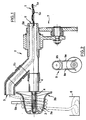
- the device according to the invention mainly comprises a supply duct (2), a winding means (3) and a braking means (9).
- the winding means (3) consists, without limitation, of a dispenser having a substantially concave area (3a) and a substantially convex area (3b) (see FIG. 1), with the aim of promoting the elimination of the turns which are form around the winding means as described below.
- any other type of winding means fulfilling the same function may be suitable: a coil composed of two parts of different taper, or composed of a cylindrical part and a plurality of needles or bars kept inclined relative to the cylindrical part at by means of a cheek, according to a technique known in the frame debtors.
- Said winding means (3) is for example made of plastic and mounted for free rotation on a shaft (4).
- the supply duct (2) is for example composed of a circular cross-section tube, bent, so that a part (2a) is in the axis of rotation of the shaft (4) and that a part (2b) extends to the periphery of the winding means.
- the outlet of the supply duct (2) is located on the side of the largest perimeter of the winding means and outside of it.
- the supply duct (2) is furthermore driven in rotation by any suitable means, for example and without limitation by a speed multiplier assembly (7) with gears driven by the shaft of the fabric take-up roller not shown.
- the braking means (9) of the preferred embodiment of the invention is composed of two bars (9a) arranged on either side of the deliverer (3) and extending perpendicular to the axis of rotation of the device, and able to clamp the turns against the coil (see diagram in Figure 2).
- a braking means of another type for example of the magnetic type.
- a cord (1) formed of at least two wicks (1 a) and (1 b) from the cutting of the two false edges of a width is introduced into the conduit (2) through the inlet (6), exits through the orifice (5) of said conduit (2), is deposited on the winding means (3) in the vicinity of its largest perimeter.
- a cord (1) formed of at least two wicks (1 a) and (1 b) from the cutting of the two false edges of a width
- said cord (1) undergoes a false twist which produces a winding of the locks relative to each other then it is deposited on the winding means (3) in the form of successive turns which, under the effect of the taper or the slope of the part (3b), and in a manner known per se, slide towards the zone of smaller perimeter (3a) where they are distributed substantially in the form at least one layer of turns.
- This layer of turns is maintained by the braking means (9), then evacuated into a recovery container (8), automatically and fa lesson known per se, on the side of the smallest perimeter of the winding means (3).
- the braking means also has the function of determining the resulting tension on the cord (1).
- the wick (1b) is wrapped around the wick (1a) until there is catching up the lengths and that the tensions of the two locks rebalance.
- the operation is all the better as the rotation speed of the duct (2) is greater than that of the fabric take-up roller, because the false twist of the cord is greater and the regulation better.
- the device according to the invention has the advantage of being self-priming, an advantage which is not found in the devices known from the prior art.
Landscapes
- Engineering & Computer Science (AREA)
- Textile Engineering (AREA)
- Looms (AREA)
- Auxiliary Weaving Apparatuses, Weavers' Tools, And Shuttles (AREA)
- Preliminary Treatment Of Fibers (AREA)
Claims (4)
Priority Applications (3)
| Application Number | Priority Date | Filing Date | Title |
|---|---|---|---|
| FR8501259A FR2576610B1 (fr) | 1985-01-28 | 1985-01-28 | Procede et dispositif pour evacuer les meches de dechets sur un metier a tisser |
| EP19860401607 EP0253036B1 (de) | 1986-07-18 | 1986-07-18 | Verfahren und Vorrichtung zum Abziehen vom Gewebekantenabfall in Webmaschinen |
| DE8686401607T DE3662406D1 (en) | 1986-07-18 | 1986-07-18 | Process and apparatus to draw off waste selvedge in looms |
Applications Claiming Priority (1)
| Application Number | Priority Date | Filing Date | Title |
|---|---|---|---|
| EP19860401607 EP0253036B1 (de) | 1986-07-18 | 1986-07-18 | Verfahren und Vorrichtung zum Abziehen vom Gewebekantenabfall in Webmaschinen |
Publications (2)
| Publication Number | Publication Date |
|---|---|
| EP0253036A1 EP0253036A1 (de) | 1988-01-20 |
| EP0253036B1 true EP0253036B1 (de) | 1989-03-15 |
Family
ID=8196325
Family Applications (1)
| Application Number | Title | Priority Date | Filing Date |
|---|---|---|---|
| EP19860401607 Expired EP0253036B1 (de) | 1985-01-28 | 1986-07-18 | Verfahren und Vorrichtung zum Abziehen vom Gewebekantenabfall in Webmaschinen |
Country Status (3)
| Country | Link |
|---|---|
| EP (1) | EP0253036B1 (de) |
| DE (1) | DE3662406D1 (de) |
| FR (1) | FR2576610B1 (de) |
Families Citing this family (2)
| Publication number | Priority date | Publication date | Assignee | Title |
|---|---|---|---|---|
| FR2576610B1 (fr) * | 1985-01-28 | 1988-03-18 | Alsacienne Constr Mat Tex | Procede et dispositif pour evacuer les meches de dechets sur un metier a tisser |
| BE1003533A3 (nl) * | 1989-10-04 | 1992-04-14 | Picanol Nv | Werkwijze en inrichting voor het verzamelen van stof en afval bij weefmachines. |
Family Cites Families (8)
| Publication number | Priority date | Publication date | Assignee | Title |
|---|---|---|---|---|
| US2163711A (en) * | 1937-06-12 | 1939-06-27 | Western Electric Co | Strand handling apparatus |
| FR1526782A (fr) * | 1964-05-30 | 1968-05-31 | Prince Jidosha Kogyo Kabushiki | Dispositif pour saisir et guider les bords d'une trame qui se déplacent |
| BE759414A (fr) * | 1970-01-20 | 1971-04-30 | Diederichs S A Atel | Dispositif assurant l'elimination de la ou des fausses lisieresdans lesmetiers a tisser sans navette |
| CH514704A (de) * | 1970-04-30 | 1971-10-31 | Rueti Ag Maschf | Verfahren und Einrichtung zum Bilden einer Hilfskante beim Weben |
| FR2486972A1 (fr) * | 1980-07-21 | 1982-01-22 | Saurer Diederichs Sa | Dispositif de controle des cordons de fausse lisiere, pour machine a tisser sans navette |
| JPS57149532A (en) * | 1981-03-06 | 1982-09-16 | Tsudakoma Ind Co Ltd | Weft yarn storing apparatus for fluid jet type loom |
| US4513791A (en) * | 1983-02-01 | 1985-04-30 | Burlington Industries, Inc. | Leno selvaging and stretch nozzle system |
| FR2576610B1 (fr) * | 1985-01-28 | 1988-03-18 | Alsacienne Constr Mat Tex | Procede et dispositif pour evacuer les meches de dechets sur un metier a tisser |
-
1985
- 1985-01-28 FR FR8501259A patent/FR2576610B1/fr not_active Expired
-
1986
- 1986-07-18 DE DE8686401607T patent/DE3662406D1/de not_active Expired
- 1986-07-18 EP EP19860401607 patent/EP0253036B1/de not_active Expired
Also Published As
| Publication number | Publication date |
|---|---|
| DE3662406D1 (en) | 1989-04-20 |
| EP0253036A1 (de) | 1988-01-20 |
| FR2576610B1 (fr) | 1988-03-18 |
| FR2576610A1 (fr) | 1986-08-01 |
Similar Documents
| Publication | Publication Date | Title |
|---|---|---|
| EP0253036B1 (de) | Verfahren und Vorrichtung zum Abziehen vom Gewebekantenabfall in Webmaschinen | |
| FR2499044A1 (fr) | Procede et dispositif d'alimentation en fils sans tension et appareil pour fabriquer un fil gonflant | |
| WO2003064741A2 (fr) | Dispositif de cablage et de fixation en continu de fils suivi d'un traitement thermique complementaire | |
| FR2483967A1 (fr) | Metier a filer de preference a anneau | |
| EP1646740B1 (de) | Maschine zum kontinuierlichen fachen, zwirnen und fixieren von fäden | |
| FR2490258A1 (fr) | Appareil a cabler des fils metalliques | |
| FR2521600A1 (fr) | Procede et appareil pour la fabrication d'un fil a ame | |
| FR2466531A1 (fr) | Broche de filage ou de retordage a double torsion a d ispositif d'enfilage pneumatique | |
| EP0018926B1 (de) | Doppeldrahtzwirnvorrichtung | |
| FR2593524A1 (fr) | Procede et appareil pour la fabrication d'un fil par torsion d'une meche de fibres etirees. | |
| FR2739107A1 (fr) | Dispositif de texturation pour une installation d'ennoblissement de fil | |
| EP1470274A1 (de) | Vorrichtung zum kontinuierlichen kablieren und fixieren von fäden und anschliessend ergänzender wärmebehandlung | |
| FR2567162A1 (fr) | Appareil pour la fabrication d'un fil place a la suite d'un banc d'etirage pour tordre une meche de fibres etiree et l'entourer de fibres enveloppantes. | |
| FR2717505A1 (fr) | Dispositif pour sécher et encoller un fil textile en mouvement et machine comportant un tel dispositif. | |
| EP0510735B1 (de) | Vorfadenspeicher für Webmaschinen | |
| FR2587539A1 (fr) | Appareil pour enrouler un filament autour d'un gabarit | |
| FR2825693A1 (fr) | Plateau tournant de depot de rubans de fibres en sortie de bancs d'etirage ou cardes | |
| FR2650307A1 (fr) | Machine de transformation de fil avec un organe dispose entre deux delivreurs et permettant l'introduction automatique du fil lors de la relance | |
| FR2667879A1 (fr) | Machine de cablage de fils comportant un dispositif regulateur perfectionne. | |
| EP0468898A1 (de) | Verfahren und Einrichtung zur Moulinierung von in Form von Kuchen aufgewickelten Fäden und ganz besonders von Glasfäden | |
| BE1008353A3 (fr) | Dispositif pour soumettre en continu des fibres en forme de fil a un traitement thermique par voie humide. | |
| CH476881A (fr) | Dispositif de fabrication de grilles non tissées | |
| EP0768420A1 (de) | Quetschvorrichtung für Garne | |
| FR2462494A1 (fr) | Appareil perfectionne pour le filage de fil par fibres liberees | |
| FR2679260A1 (fr) | Dispositif d'enroulement en bobine d'un ruban de fibres textiles. |
Legal Events
| Date | Code | Title | Description |
|---|---|---|---|
| PUAI | Public reference made under article 153(3) epc to a published international application that has entered the european phase |
Free format text: ORIGINAL CODE: 0009012 |
|
| 17P | Request for examination filed |
Effective date: 19870603 |
|
| AK | Designated contracting states |
Kind code of ref document: A1 Designated state(s): BE CH DE IT LI |
|
| 17Q | First examination report despatched |
Effective date: 19880520 |
|
| ITF | It: translation for a ep patent filed |
Owner name: BARZANO' E ZANARDO MILANO S.P.A. |
|
| GRAA | (expected) grant |
Free format text: ORIGINAL CODE: 0009210 |
|
| AK | Designated contracting states |
Kind code of ref document: B1 Designated state(s): BE CH DE IT LI |
|
| REF | Corresponds to: |
Ref document number: 3662406 Country of ref document: DE Date of ref document: 19890420 |
|
| PLBE | No opposition filed within time limit |
Free format text: ORIGINAL CODE: 0009261 |
|
| STAA | Information on the status of an ep patent application or granted ep patent |
Free format text: STATUS: NO OPPOSITION FILED WITHIN TIME LIMIT |
|
| 26N | No opposition filed | ||
| PGFP | Annual fee paid to national office [announced via postgrant information from national office to epo] |
Ref country code: BE Payment date: 19900607 Year of fee payment: 5 |
|
| PGFP | Annual fee paid to national office [announced via postgrant information from national office to epo] |
Ref country code: CH Payment date: 19900628 Year of fee payment: 5 |
|
| ITTA | It: last paid annual fee | ||
| PGFP | Annual fee paid to national office [announced via postgrant information from national office to epo] |
Ref country code: DE Payment date: 19900928 Year of fee payment: 5 |
|
| PG25 | Lapsed in a contracting state [announced via postgrant information from national office to epo] |
Ref country code: LI Effective date: 19910731 Ref country code: CH Effective date: 19910731 Ref country code: BE Effective date: 19910731 |
|
| BERE | Be: lapsed |
Owner name: SOC. ALSACIENNE DE CONSTRUCTION DE MATERIEL TEXTI Effective date: 19910731 |
|
| REG | Reference to a national code |
Ref country code: CH Ref legal event code: PL |
|
| PG25 | Lapsed in a contracting state [announced via postgrant information from national office to epo] |
Ref country code: DE Effective date: 19920401 |
|
| PG25 | Lapsed in a contracting state [announced via postgrant information from national office to epo] |
Ref country code: IT Free format text: LAPSE BECAUSE OF NON-PAYMENT OF DUE FEES;WARNING: LAPSES OF ITALIAN PATENTS WITH EFFECTIVE DATE BEFORE 2007 MAY HAVE OCCURRED AT ANY TIME BEFORE 2007. THE CORRECT EFFECTIVE DATE MAY BE DIFFERENT FROM THE ONE RECORDED. Effective date: 20050718 |