EP0767005B1 - Beschichtungsvorrichtung mit rotationszerstäuber - Google Patents
Beschichtungsvorrichtung mit rotationszerstäuber Download PDFInfo
- Publication number
- EP0767005B1 EP0767005B1 EP96908347A EP96908347A EP0767005B1 EP 0767005 B1 EP0767005 B1 EP 0767005B1 EP 96908347 A EP96908347 A EP 96908347A EP 96908347 A EP96908347 A EP 96908347A EP 0767005 B1 EP0767005 B1 EP 0767005B1
- Authority
- EP
- European Patent Office
- Prior art keywords
- ring
- atomizing head
- rotary atomizing
- coating machine
- shaping air
- Prior art date
- Legal status (The legal status is an assumption and is not a legal conclusion. Google has not performed a legal analysis and makes no representation as to the accuracy of the status listed.)
- Expired - Lifetime
Links
Images


Classifications
-
- B—PERFORMING OPERATIONS; TRANSPORTING
- B05—SPRAYING OR ATOMISING IN GENERAL; APPLYING FLUENT MATERIALS TO SURFACES, IN GENERAL
- B05B—SPRAYING APPARATUS; ATOMISING APPARATUS; NOZZLES
- B05B5/00—Electrostatic spraying apparatus; Spraying apparatus with means for charging the spray electrically; Apparatus for spraying liquids or other fluent materials by other electric means
- B05B5/025—Discharge apparatus, e.g. electrostatic spray guns
- B05B5/04—Discharge apparatus, e.g. electrostatic spray guns characterised by having rotary outlet or deflecting elements, i.e. spraying being also effected by centrifugal forces
-
- B—PERFORMING OPERATIONS; TRANSPORTING
- B05—SPRAYING OR ATOMISING IN GENERAL; APPLYING FLUENT MATERIALS TO SURFACES, IN GENERAL
- B05B—SPRAYING APPARATUS; ATOMISING APPARATUS; NOZZLES
- B05B5/00—Electrostatic spraying apparatus; Spraying apparatus with means for charging the spray electrically; Apparatus for spraying liquids or other fluent materials by other electric means
- B05B5/025—Discharge apparatus, e.g. electrostatic spray guns
- B05B5/053—Arrangements for supplying power, e.g. charging power
- B05B5/0533—Electrodes specially adapted therefor; Arrangements of electrodes
-
- B—PERFORMING OPERATIONS; TRANSPORTING
- B05—SPRAYING OR ATOMISING IN GENERAL; APPLYING FLUENT MATERIALS TO SURFACES, IN GENERAL
- B05B—SPRAYING APPARATUS; ATOMISING APPARATUS; NOZZLES
- B05B5/00—Electrostatic spraying apparatus; Spraying apparatus with means for charging the spray electrically; Apparatus for spraying liquids or other fluent materials by other electric means
- B05B5/025—Discharge apparatus, e.g. electrostatic spray guns
- B05B5/04—Discharge apparatus, e.g. electrostatic spray guns characterised by having rotary outlet or deflecting elements, i.e. spraying being also effected by centrifugal forces
- B05B5/0403—Discharge apparatus, e.g. electrostatic spray guns characterised by having rotary outlet or deflecting elements, i.e. spraying being also effected by centrifugal forces characterised by the rotating member
- B05B5/0407—Discharge apparatus, e.g. electrostatic spray guns characterised by having rotary outlet or deflecting elements, i.e. spraying being also effected by centrifugal forces characterised by the rotating member with a spraying edge, e.g. like a cup or a bell
-
- B—PERFORMING OPERATIONS; TRANSPORTING
- B05—SPRAYING OR ATOMISING IN GENERAL; APPLYING FLUENT MATERIALS TO SURFACES, IN GENERAL
- B05B—SPRAYING APPARATUS; ATOMISING APPARATUS; NOZZLES
- B05B5/00—Electrostatic spraying apparatus; Spraying apparatus with means for charging the spray electrically; Apparatus for spraying liquids or other fluent materials by other electric means
- B05B5/025—Discharge apparatus, e.g. electrostatic spray guns
- B05B5/04—Discharge apparatus, e.g. electrostatic spray guns characterised by having rotary outlet or deflecting elements, i.e. spraying being also effected by centrifugal forces
- B05B5/0426—Means for supplying shaping gas
-
- B—PERFORMING OPERATIONS; TRANSPORTING
- B05—SPRAYING OR ATOMISING IN GENERAL; APPLYING FLUENT MATERIALS TO SURFACES, IN GENERAL
- B05B—SPRAYING APPARATUS; ATOMISING APPARATUS; NOZZLES
- B05B15/00—Details of spraying plant or spraying apparatus not otherwise provided for; Accessories
- B05B15/50—Arrangements for cleaning; Arrangements for preventing deposits, drying-out or blockage; Arrangements for detecting improper discharge caused by the presence of foreign matter
Definitions
- This invention relates to a rotary atomizing head type coating machine with an indirect charging system, which is particularly suitable for use with low resistance paints such as water-base paints and metallic paints.
- a rotary atomizing head type coating machine according to preamble of claim 1 is known from JP-A-6134353.
- a rotary atomizing head type coating machine while a rotary atomizing head is put in high speed rotation, a high voltage is applied across the atomizing head and an object to be coated, and a paint is supplied to the rotary atomizing head to undergo atomization and charging there. Atomized and charged paint particles are caused to fly along an electrostatic field toward a coating object, which is located axially forward of the atomizing head, and deposit on the coating object.
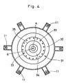
- FIG. 11 illustrated in Fig. 11 is a prior art rotary atomizing head type coating machine employing an indirect charging system.
- a coating machine body which is mounted on a reciprocator (not shown).
- an air motor 2 of metallic material consisting of an air bearing 2A and a drive section 2B, along with valve devices (not shown) including a paint valve and a dump valve.
- the coating machine body 1 is enshrouded under a synthetic resin cover 3.
- the air motor 2 is grounded through a cable 2C.
- the above-mentioned synthetic resin cover 3 is formed of an insulating synthetic resin material such as polyethylene terephthalate (PET), polyacetal (POM), polyamide (PA), polyethylene (PE), polypropyrene (PP) or the like.
- Indicated at 4 is a rotational shaft of metallic material, which is rotatably supported in the air bearing 2A of the air motor 2.
- the fore end of the rotational shaft 4 is projected out of the coating machine body 1, while its base end is coupled with the drive section 2B of the air motor 2, thereby driving for high speed rotation.
- Denoted at 5 is a bell type rotary atomizing head of metallic material which is provided at the fore end of the rotational shaft 4, the rotary atomizing head 5 having a cup-shaped circumferential surface 5A, an inner paint smoothing surface 5B and a paint releasing edge 5C.
- Indicated at 6 is a center feed type paint supply pipe which is passed internally of the rotational shaft 4, the paint supply pipe 6 having its fore end extended into the rotary atomizing head 5 and connected at its base end to a paint valve which is in communication with a paint tank through a paint pipe (both not shown).
- the reference numeral 7 indicates a shaping air ring which is threaded on a fore end portion of the synthetic resin cover 3 on the front side of the coating machine body 1.
- This shaping air ring 7 is located at the fore end of the coating machine body 1 in a position on the rear side of the rotary atomizing head 5 in such a way as to circumvent the circumferential surfaces 5A of the atomizing head 5.
- the shaping air ring 7 is constituted by an inner ring 8 which is formed of an insulating synthetic resin material, and an outer ring 9 likewise of an insulating synthetic resin material which is positioned around the outer periphery of the inner ring 8.
- an air outlet 10 formed between the inner and outer rings is an air outlet 10 in the form of an annular gap through which shaping air is spurted out as indicated by arrow A to generate air flows.
- the inner ring 8 and outer ring 9 are formed of insulating synthetic resin material such as polyether sulfone (PES), polyphenylene sulfide (PPS), polyether imide (PEI), polyether ether ketone (PEEK) or the like.
- PES polyether sulfone
- PPS polyphenylene sulfide
- PEI polyether imide
- PEEK polyether ether ketone
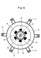
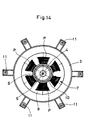
- Indicated at 11 are six external electrodes (only two electrodes are shown in the drawings) which are located in equidistant spaced positions, radially outward of the synthetic resin cover 3 and rearward of the paint releasing edges 5C of the rotary atomizing head 5. These external electrodes 11 are applied with a high voltage (e.g., -60kV to -90kV) from an external high voltage generator (not shown) to charge paint particles to be sprayed from the paint releasing edges 5C of the above-described rotary atomizing head 5.
- a high voltage e.g., -60kV to -90kV
- the air motor 2 Since the air motor 2 is grounded through the cable 2C, the air motor 2, rotational shaft 4 and rotary atomizing head 5, which are all formed of a metallic material, are maintained at the same earth potential.
- the rotational shaft 4 and rotary atomizing head 5 are put in high speed rotation by the air motor 2 on the coating machine body 1, and the paint valve is opened to supply a paint to the rotary atomizing head 5 through the paint supply pipe 6.
- the paint which has been fed to the rotary atomizing head 5 is spread into a thin film-like shape on the paint smoothing surface 5B under the influence of the centrifugal force resulting from the rotation.
- the liquid paint film is split into liquid threads as it is thrown radially outward from the paint releasing edges 5C, and the liquid threads are eventually broken and atomized into fine particle.
- atomized paint particles are charged with high voltage, and the resulting charged paint particles are urged to fly toward the coating object which is connected to the ground, and deposit on the surfaces of the coating object.
- the coating machine body 1 is prevented from being contaminated with negatively charged paint particles by covering the machine body 1, except the rotary atomizing head 5, with an insulating synthetic resin material like the shaping air ring 7 and synthetic resin cover 3. More specifically, when a high voltage is applied to the respective external electrodes 11, the component parts of synthetic resin material including the shaping air ring 7 and the resin cover 3 are negatively charged under the influence of negative ions generated by the external electrodes 11. Consequently, due to a phenomenon of homopolar repulsions, negative ions charged on the shaping air ring 7 and resin cover 3 repel and keep the negatively charged paint particles from depositing on the surfaces of the cover 3 and ring 7.
- the shaping air ring 7 of insulating synthetic resin material is simply held in contact, through that synthetic resin material, with the air motor 2 which is connected to the ground.
- the rotary atomizing head 5 is directly connected to the ground through the rotational shaft 4 and air motor 2 of metallic material. Therefore, looking at the potential relations from the side of the external electrodes 11 which are applied with a high negative voltage, the shaping air ring 7 is electrically more closer to the positive side than the rotary atomizing head 5 which is connected to the ground.
- paint particles sprayed from the paint releasing edges 5C of the rotary atomizing head 5 are negatively charged while being passage through the ionization zones of the external electrodes 11, and the charged paint particles are urged to fly toward and deposit on a coating object which is at the earth potential (with a tendency toward the positive when looked at from the side of the external electrodes 11).
- a part of paint particles are urged to flow in a forward direction from behind the shaping air ring 7 entrained on air vortices generated by rotation of the rotary atomizing head 5.
- negative ions around the fore end of the air shaping ring 7 are lessened and leaned out by the occurrence of weak positive discharges as mentioned hereinbefore.
- a rotary atomizing head type coating machine basically including a coating machine body circumferentially enshrouded under a synthetic resin cover, an air motor provided within the coating machine body and grounded to the earth potential, a rotary atomizing head provided at the fore end of the coating machine body and coupled with the air motor, the rotary atomizing head being terminated with paint releasing edges at the fore end thereof, a shaping air ring provided at the fore end of the coating machine body in such a way as to circumvent the outer periphery of the rotary atomizing head and having an air outlet to spurt shaping air from behind the paint releasing edges of the rotary atomizing head, and external electrodes positioned radially on the outer side of the coating machine body and externally applied with a high voltage to charge paint particles sprayed from the paint releasing edges of the rotary atomizing head, characterized in that at least part of the shaping air ring is formed of a
- the annular repulsion electrode is directly connected to the ground through the air motor, so that stronger positive discharges occur at the annular repulsion electrode than at the paint releasing edges.
- clouds of negative ions which are generated by the external electrodes are pulled toward stronger positive discharges on the side of the shaping air ring, preventing deposition of paint particles on the air shaping ring by the phenomenon of homopolar repulsions which occur between the negatively charged paint particles and clouds of negative ions.
- the shaping air ring may be constituted by an inner ring formed of a conductive material and electrically connected to the air motor, an outer ring formed of an insulating synthetic resin material and positioned in such a way as to enshroud the outer periphery of the inner ring, and an air outlet formed and defined between the inner and outer rings, the above-mentioned annular repulsion electrode being constituted by a fore end portion of the inner ring.
- the air shaping ring may be constituted by a ring body formed of an insulating synthetic resin material and having an air outlet at the fore end thereof, a conductive ring formed on the inner periphery of the shaping air ring by means of a conductive material and electrically connected to the air motor, the above-mentioned annular repulsion electrode being constituted by a fore end portion of the conductive ring.
- the shaping air ring may be constituted by a ring body formed of an insulating synthetic resin material and having an air outlet on a flat front face thereof, a conductive ring formed on the inner periphery of the shaping air ring body by the use of a conductive material and electrically connected to the air motor, and an annular repulsion electrode formed on the front face of the shaping air ring by a separate member from the conductive ring and electrically connected to the conductive ring.
- clouds of negative ions pulled toward the annular repulsion electrode can be carried forward toward the outer periphery of the rotary atomizing head by shaping air spurted from the respective air outlets, contributing to facilitate the negative charging of paint particles which are released from the paint releasing edges of the rotary atomizing head.
- a conductive metal may be used as the conductive material which constitutes the above-described annular repulsion electrode.
- a conductive synthetic resin material may be used as the conductive material which constitutes the annular repulsion electrode if desired.
- the shaping air ring according to the present invention may be of an insulating synthetic resin material, and provided with a conductive film layer formed on the inner periphery of the shaping air ring and electrically connected to the air motor, and an annular repulsion electrode constituted by at least part of the conductive film layer.
- the shaping air ring may be constituted by an inner ring formed of an insulating synthetic resin material, an outer ring formed of an insulating synthetic resin material and positioned in such a way as to cover the circumference of the inner ring, an air outlet formed between the inner and outer rings, a conductive film layer coated with a conductive paint on the inner periphery of the inner ring, and an annular repulsion electrode constituted by a fore end portion of the conductive film layer.
- the shaping air ring is constituted by a ring body formed of an insulating synthetic resin material and having air outlets on a flat front face thereof, a conductive film layer coated with a conductive paint on the inner periphery and extended to the flat front face of the shaping air ring body, and an annular repulsion electrode constituted by a fore end portion of the conductive film layer.
- the above-described annular repulsion electrode can be formed as an annular ring-like body which circumvents circumferential surfaces of the rotary atomizing head in the vicinity thereof.
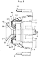
- FIGs. 1 and 2 there is shown a first embodiment of the present invention.
- a shaping air ring which is threaded on a fore end portion of a synthetic resin cover 3 at the fore end of a coating machine body 1 proper.
- the shaping air ring 21 is provided at the fore end of the coating machine body 1 at a position behind a rotary atomizing head 5 in such a manner as to circumvent the circumferential surfaces 5A of the latter.
- the shaping air ring 21 is constituted by an inner ring 22 which is formed of a conductive material, for example, a metallic material such as copper, stainless steel, aluminum or the like, an outer ring 23 which is positioned to circumvent the outer periphery of the inner ring 22 and formed of an insulating synthetic resin material such as, for example, polyether sulfone (PES), polyphenylene sulfide (PPS), polyether imide (PEI), polyether ether ketone (PEEK) or the like, and an annular air outlet 24 located at the fore ends of the inner and outer rings 23 to spurt shaping air toward the outer periphery of the rotary atomizing head 5.
- the inner ring 22 has its base end 22A held in contact with and electrically connected to the outer periphery of the air motor 2, which is grounded to the earth.
- annular repulsion electrode 25 Denoted at 25 is an annular repulsion electrode which is provided at a fore end portion 22B of the inner ring 22.
- This annular repulsion electrode 25 is formed in a ring-like form integrally with the inner ring 22 and located closely around circumferential surfaces 5A of the rotary atomizing head 5.
- the rotary atomizing head type coating machine of this embodiment operates in the same manner as the prior art counterpart described hereinbefore.
- the inner ring 22 of the shaping air ring 21 is formed of a metallic material, and its base end 22A can be directly connected to the ground through the air motor 2, forming the annular repulsion electrode 25 at its fore end 22B.
- the rotary atomizing head 5 of a metallic material is also directly grounded to the earth through the air motor 2, so that the annular repulsion electrode 25 of the shaping air ring 21 and the rotary atomizing head 5 remain at the same potential (at the earth potential).
- the distance from the external electrodes 11 to the annular repulsion electrode 25 is shorter than the distance from the external electrodes 11 to the paint releasing edges 5C of the rotary atomizing head 5. Therefore, positive discharges occur in a greater degree at the annular repulsion electrode 25, which is located closer to the external electrodes 11, than at the paint releasing edge 5C which is more distant from the external electrodes 11. As a result, clouds of negative ions generated by the respective external electrodes 11 are pulled toward the annular repulsion electrode 25 because of the stronger positive discharges, and tend to linger in the vicinity of the annular repulsion electrode 25 in enlarged and thickened state.
- paint particles which have been released from the paint releasing edges 5C of the rotary atomizing head 5 and negatively charged by the high voltage external electrodes 11, are securely kept from depositing on the shaping air ring 21 by homopolar repulsions occurring between negatively charged paint particles and the clouds of negative ions.
- the shaping air ring 21 which has the inner ring 22 surrounded by the outer ring 23 of an insulating synthetic resin material can secure a sufficient insulation distance between the inner ring 22 and each one of the external electrodes 11, thereby preventing shortcircuiting between the annular repulsion electrode 25 of the shaping air ring 21 and the external electrodes 11, and guaranteeing high safety by suppressing positive discharges at the annular repulsion electrode 25.
- a large quantity of negative ions which have been pulled toward and around the annular repulsion electrode 25 can be carried forward toward the outer periphery of the rotary atomizing head 5. Accordingly, paint particles released from the paint releasing edges 5C of the rotary atomizing head 5 can be effectively charged by the forwardly carried negative ions in such a manner as to enhance the paint deposition efficiency on a coating object.
- the shaping air ring 21 of this embodiment uses the inner ring 22 of metallic material, forming the annular repulsion electrode 25 at the fore end thereof.
- the annular repulsion electrode 25 which is located at the fore end of the shaping air ring 21 is capable of inducing strong positive discharges to attract clouds of negative ions thereto, so that mist of paint particles is securely prevented from depositing on the shaping air ring 21 and resin cover 3 by homopolar repulsions occurring between negative ion clouds and negatively charged paint particles.
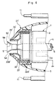
- a second embodiment of the present invention which is characterized in that the shaping air ring is constituted by a single ring structure and provided with a plural number of air outlet holes at its fore end, and in that an annular repulsion electrode is formed at the fore end of a conductive ring which is fitted on the inner periphery of the shaping air ring.
- the shaping air ring is constituted by a single ring structure and provided with a plural number of air outlet holes at its fore end, and in that an annular repulsion electrode is formed at the fore end of a conductive ring which is fitted on the inner periphery of the shaping air ring.
- a shaping air ring which is employed in this embodiment in place of the shaping air ring 21 of the first embodiment.
- the shaping air ring 31 is mounted in position at the fore end of the coating machine body 1, in threaded engagement with a fore end portion of the synthetic resin cover 3 at the fore end of the coating machine body 1 in such a manner as to circumvent circumferential surfaces 5A at a position rearward of the rotary atomizing head 5.
- the shaping air ring 31 includes a ring body 32 substantially of J-shape in section with a flat front face 32A, which is formed of an insulating synthetic resin material such as, for example, polyether sulfone (PES), polyphenylene sulfide (PPS), polyether imide (PEI), polyether ether ketone (PEEK) or the like, and a plural number of air outlet holes 33 which are arranged circularly on the flat front face 32A of the ring body 32 to spurt shaping air toward the outer periphery of the rotary atomizing head 5.
- PES polyether sulfone
- PPS polyphenylene sulfide
- PEI polyether imide
- PEEK polyether ether ketone
- Indicated at 34 is a conductive ring which is integrally cast on the inner periphery of the ring body 32 by the use of a metallic conductive material such as copper, stainless steel, aluminum or the like.
- the conductive ring 34 has its base end 34A electrically conductively in contact with the outer periphery of the air motor 2, and has its fore end 34B extended up to the front end face 32A of the shaping air ring 31.
- Denoted at 35 is an annular repulsion electrode which is provided in a fore end portion 34B of the conductive ring 34 of the shaping air ring 31, the annular repulsion electrode 35 being formed integrally with the conductive ring 34 in such a way as to circumvent the circumferential surfaces 5A of the rotary atomizing head 5 in the vicinity thereof.
- the shaping air ring 31 on the rotary atomizing head type coating machine induces stronger positive discharges at the annular repulsion electrode 35 than at the paint releasing edges 5C of the rotary atomizing head 5, substantially in the same manner as in the foregoing first embodiment.
- clouds of negative ions are enlarged and thickened as they are pulled toward the positive discharges at the annular repulsion electrode 35, preventing deposition of charged paint particles on the shaping air ring 31 by homopolar repulsions between clouds of negative ions and negatively charged paint particles.
- a third embodiment of the invention which is characterized in that the shaping air ring is constituted by a single integral ring structure with air outlet holes on a front face thereof, a conductive ring is provided on the inner periphery of the shaping air ring, and an annular repulsion electrode is provided on the front face by fixing thereon a separate member which is electrically connected to the conductive ring.
- the shaping air ring is constituted by a single integral ring structure with air outlet holes on a front face thereof
- a conductive ring is provided on the inner periphery of the shaping air ring
- an annular repulsion electrode is provided on the front face by fixing thereon a separate member which is electrically connected to the conductive ring.
- This shaping air ring 41 is constituted by a ring body 42 substantially of a J-shape in section having a flat front face 42A, which is formed of an insulating synthetic resin material similar to that of the shaping air ring 31 of the second embodiment, and a plural number of air outlet holes 43 which are arranged circularly on the front face 42A for spurting shaping air toward circumferential surfaces of the rotary atomizing head 5.
- Denoted at 44 is a conductive ring which is integrally cast on the inner periphery of the ring body 42 by the use of a metallic conductive material such as, for example, copper, stainless steel, aluminum or the like.
- the conductive ring 44 has its base end 44A held in contact with the outer periphery of the air motor 2 for electrical conduction therethrough.
- annular repulsion electrode which is constituted by a member separate from the conductive ring 44 and fixed on the front face 42A of the ring body 42.
- This annular repulsion electrode 45 is in the form of a flat ring-like plate and located to circumvent the circumferential surfaces 5A of the rotary atomizing head 5 in the vicinity thereof. Further, the annular repulsion electrode 45 is connected to a fore end portion 44B of the conductive ring 44, that is to say, connected through the conductive ring 44 to the air motor 2 which is maintained at the earth potential.
- the shaping air ring 41 can produce the same operational effects as the counterpart in the foregoing second embodiment. Besides, since the annular repulsion electrode 45 is more positively provided on the front face 42A of the ring body 42 electrically in contact with the conductive ring 44, the annular repulsion electrode 45 has a broader surface area which is capable of generating stronger positive discharges for the purpose of suppressing deposition of paint particles on the shaping air ring 41 all the more.
- FIGs. 6 to 8 show fourth, fifth and sixth embodiments of the present invention.
- those components which have corresponding counterparts in the foregoing first to third embodiments are designated by corresponding reference numerals or characters each attached with an apostrophe (').
- the fourth embodiment shown in Fig. 6 uses a shaping air ring 21' which is formed with an inner ring 22' of a conductive synthetic resin material in place of the inner ring 22 of the shaping air ring 21 in the above-described first embodiment.
- the inner ring 22' has its base end 22A' held in contact with and electrically connected to the outer periphery of the air motor 2, while forming an annular repulsion electrode 25' at its fore end portion 22B'.
- the inner ring 22' is formed of a conductive synthetic resin material which is imparted with conductivity by mixing metal fiber or powder into a synthetic resin material of the sort as mentioned hereinbefore.
- the fifth embodiment shown in Fig. 7 uses a shaping air ring 31' with a conductive ring 34' of a conductive synthetic resin material in place of the metallic conductive ring 34 provided on the shaping air ring 31 of the foregoing second embodiment.
- the sixth embodiment shown in Fig. 8 uses a shaping air ring 41' with a conductive ring 44 of a conductive synthetic resin material in place of the metallic conductive ring 44 provided on the air shaping ring 41 of the foregoing third embodiment.
- the shaping air rings 21', 31' and 41' can produce substantially the same operational effects as in the foregoing first to third embodiments.
- the shaping air rings 21', 31' and 41' which are constituted by a molded structure of a mixture of insulating and conductive synthetic resin materials can contribute to enhance the production efficiency, in other words, to reduce the production cost as compared with the shaping air rings in the first to third embodiments.
- a seventh embodiment of the invention which is characterized in that the shaping air ring is constituted by a single member and provided with an annular repulsion electrode at the fore end of a conductive film layer formed on the inner periphery of the shaping air ring.
- the shaping air ring is constituted by a single member and provided with an annular repulsion electrode at the fore end of a conductive film layer formed on the inner periphery of the shaping air ring.
- the shaping air ring constituted by an inner ring 52 which is formed of an insulating synthetic resin material similarly to the prior art shaping air ring 7 described hereinbefore, an outer ring 53 similarly formed of an insulating synthetic resin material in such a shape as to enshroud the outer periphery of the inner ring 52, and an annular air outlet 54 formed between the fore ends of the inner and outer rings 52 and 53 to spurt shaping air toward the outer periphery of the rotary atomizing head 5.
- Denoted at 55 is a conductive film layer which is formed substantially fully around the inner periphery of the inner ring 52, for example, by application of a conductive paint or the like, and which has its base end portion 55A held in contact with and electrically connected to the outer periphery of the air motor 2.
- end portion 55B of the conductive film layer 55 is extended onto the front end face of the inner ring 52 up to a point near the air outlet 54.
- the conductive film layer 55 there may be used, for example, a conductive paint kneaded with copper powder, aluminum powder, carbon, metal oxide or the like.
- annular repulsion electrode which is provided at a fore end portion 55B of the above-described conductive film layer 55.
- the annular repulsion electrode 56 is formed integrally with the conductive film layer 55 in such a way as to circumvent the circumferential surfaces 5A of the rotary atomizing head 5 in the vicinity thereof.
- This embodiment which is arranged in the manner just described can also produce substantially the same operational effects as in the foregoing embodiments in that negatively charged paint particles are securely prevented from depositing on the shaping air ring 51 by the phenomenon of homopolar repulsions of negative ion clouds occurring in the vicinity of the annular repulsion electrode 55.
- the film coating process as well as the fabrication process can be simplified, coupled with an advantage that electrical conductivity or resistance can be set at an arbitrary value according to the film thickness.
- Fig. 10 Shown in Fig. 10 is an eighth embodiment of the invention, which is characterized in that the shaping air ring is constituted by a single member, with a plural number of air outlets at its fore end, and in that an annular repulsion electrode is constituted by a fore end portion of a conductive film layer formed on its inner periphery.
- the shaping air ring is constituted by a single member, with a plural number of air outlets at its fore end
- an annular repulsion electrode is constituted by a fore end portion of a conductive film layer formed on its inner periphery.
- shaping air ring which is used in this embodiment.
- This shaping air ring 61 is threaded into a synthetic resin cover 3 at the fore end of the paint coating machine body 1, and located in a position behind the rotary atomizing head 5 in such a manner as to circumvent circumferential surfaces 5A of the rotary atomizing head 5.
- the shaping air ring 61 is constituted by a ring body proper 62 which is formed of an insulating synthetic resin material substantially in a J-shape in section with a front face 62A similarly to the counterparts in the foregoing embodiments, and a plural number of air outlet holes 63 which are arranged circularly on the front face 62A of the ring body 62 to spurt shaping air in a forward direction toward the outer periphery of the rotary atomizing head 5.
- Indicated at 64 is a conductive film layer which is formed substantially fully around the inner periphery of the ring body 62, for example, by coating thereon a conductive paint or the like.
- the conductive film layer 64 is held in contact with and electrically connected with to outer periphery of the air motor 3 at its base end 64A, and has its fore end 64B extended forward as far as the front face 62A of the ring body 62.
- annular repulsion electrode 65 Denoted at 65 is an annular repulsion electrode which is provided in a fore end portion 64B of the conductive film layer 64.
- This annular repulsion electrode 65 is formed integrally with the conductive film layer 64 as a ring-like body which circumvents the circumferential surfaces 5A of the rotary atomizing head 5 in the vicinity thereof.
- the present embodiment can also produce substantially the same operational effects as in each one of the foregoing embodiments of the present invention.
- At least part of the shaping air ring is formed of a conductive material to provide an annular repulsion electrode at least in part of the conductive material.
- the shaping air ring is constituted by an inner ring formed of a conductive material and electrically connected to the air motor, an outer ring of an insulating synthetic resin material located to enshroud the outer periphery of the inner ring, an air outlet formed between the inner and outer rings, and an annular repulsion ring constituted by a fore end portion of the inner ring.
- the shaping air ring is constituted by a ring body of an insulating synthetic resin material having an air outlets at the fore end thereof, a conductive ring of a conductive material provided on the inner periphery of the shaping air ring and electrically connected to the air motor, and an annular repulsion electrode constituted by a fore end portion of the conductive ring.
- the shaping air ring may be constituted by a ring body of an insulating synthetic resin material having an air outlets on a flat front face thereof, a conductive ring of conductive material formed on the inner periphery of the shaping air ring and electrically connected to the air motor, and an annular repulsion electrode formed on the front face of the shaping air ring by a separate member from said conductive ring and electrically connected to the conductive ring.
- the annular repulsion electrode is provided with a broader surface area and capable of generating strong plasma discharges, thereby suppressing paint deposition on the air shaping ring all the more.
- annular repulsion electrode according to the present invention can be formed of either a conductive metallic material or a conductive synthetic resin material, so that a grater variety of materials can be used in the fabrication processes from the standpoint of attaining a higher production efficiency.
- the shaping air ring can be constituted by a ring body of an insulating synthetic resin material, a conductive film layer formed on the shaping air ring and electrically connected to the air motor, and an annular repulsion electrode constituted by at least part of the conductive film layer.
- the use of the conductive film layer as an annular repulsion electrode contributes to facilitate the fabrication process of the shaping air ring.
- the use of the conductive film layer which can be formed simply by application of a conductive paint, makes easier the film forming process as well as the shaping air ring fabrication process, in addition to the advantage that the electrical conductivity or resistance of the film layer can be set at an arbitrary value according to the film thickness.
- the annular repulsion electrode which is provided as an annular ring-like body which circumvents circumferential surfaces of the rotary atomizing head at a position in the ambience of the latter, contributes to uniform and accelerated charging of paint particles which are released from the paint releasing edges of the rotary atomizing head.
Claims (10)
- Auftragsmaschine vom Rotationszerstäuberkopf-Typ mit einem Auftragsmaschinen-Körper (1), der von einer Kunstharz-Abdeckung (3) ummantelt ist, einem Luftmotor (2), der innerhalb des Auftragsmaschinen-Körpers (1) vorgesehen und auf Erdpotential gelegt ist, einem Rotationszerstäuberkopf (5), der am Vorderende des Auftragsmaschinenkörpers (1) vorgesehen und mit dem Luftmotor (2) gekoppelt ist, wobei der Rotationszerstäuberkopf (5) an seinem Vorderende mit farbabgebenden Kanten (5C) endet, einem Formungsluft-Ring (21, 31, 41, 21', 31', 41'), der am Vorderende des Auftragsmaschinenkörpers (1) derart vorgesehen ist, daß er den äußeren Rand des Rotationszerstäuberkopfes (5) umgibt, und einen Luftauslaß (24, 33, 43, 24', 33', 43') hat, um Formungsluft von hinter den farbabgebenden Kanten (5C) des Rotationszerstäuberkopfes (5) auszustoßen, und externen Elektroden (11), die radial auf der Außenseite des Auftragsmaschinenkörpers (1) angeordnet sind und an die extern eine Hochspannung angelegt ist, um Farbteilchen aufzuladen, die von den farbabgebenden Kanten (5C) des Rotationszerstäuberkopfes (5) versprüht werden, dadurch gekennzeichnet, daß:zumindest ein Teil des Formungsluft-Ringes (21, 31, 41, 21', 31', 41') aus einem leitenden Material gebildet und elektrisch mit dem Luftmotor (2) verbunden ist, und daß eine ringförmige Abstoßungselektrode (25, 35, 45, 25', 35', 45') zumindest teilweise aus dem leitenden Material gebildet ist.
- Auftragsmaschine vom Rotationszerstäuber-Typ nach Anspruch 1, wobei der Formungsluft-Ring (21, 31, 41, 21', 31', 41') durch einen inneren Ring (22, 22'), der aus einem leitenden Material gebildet und elektrisch mit dem Luftmotor (2) verbunden ist, einen äußeren Ring (23, 23'), der aus einem isolierenden Kunstharzmaterial gebildet und derart angeordnet ist, daß er den äußeren Umfang des inneren Ringes (22, 22') umgibt, und einen Luftauslaß (24, 24') gebildet wird, der zwischen dem inneren und dem äußeren Ring (22, 22', 23, 23') gebildet ist, und wobei die ringförmige Abstoßungselektrode (25, 25') durch einen vorderen Endbereich (22B, 22B') des inneren Ringes (22, 22') gebildet wird.
- Auftragsmaschine vom Rotationszerstäuber-Typ nach Anspruch 1, wobei der Formungsluft-Ring (31, 31') durch einen Ringkörper (32, 32'), der aus einem isolierenden Kunstharzmaterial gebildet ist und an seinem Vorderende einen Luftauslaß (33, 33') aufweist, und einen leitenden Ring (34, 34') gebildet wird, der am inneren Umfang des Formungsluft-Ringes (31, 31') durch Verwendung eines leitenden Materials gebildet und elektrisch mit dem Luftmotor (2) verbunden ist, und wobei die ringförmige Abstoßungselektrode (35, 35') durch einen vorderen Endbereich (34B, 34B') des leitenden Ringes (34, 34') gebildet wird.
- Auftragsmaschine vom Rotationszerstäuber-Typ nach Anspruch 1, wobei der Formungsluft-Ring (41, 41') durch einen Ringkörper (42, 42'), der aus einem isolierenden Kunstharzmaterial gebildet ist und an einer flachen Vorderfläche (42A, 42A') von ihm einen Luftauslaß (43, 43') aufweist, und einen leitenden Ring (44, 44') gebildet wird, der am inneren Umfang des Formungsluft-Ringkörpers (42, 42') durch Verwendung eines leitenden Materials gebildet und elektrisch mit dem Luftmotor(2) verbunden ist, und wobei die ringförmige Abstoßungselektrode (45, 45') auf der Vorderfläche des Formungsluft-Ringes (41, 41') durch ein von dem leitenden Ring (44, 44') separates Element gebildet und elektrisch mit dem leitenden Ring (44, 44') verbunden ist.
- Auftragsmaschine vom Rotationszerstäuber-Typ nach einem der Ansprüche 1 bis 4, wobei das die ringförmige Abstoßungselektrode (25, 35, 45, 45') bildende leitende Material ein leitendes metallisches Material ist.
- Auftragsmaschine vom Rotationszerstäuber-Typ nach einem der Ansprüche 1 bis 4, wobei das die ringförmige Abstoßungselektrode (25', 35') bildende leitende Material ein leitendes Kunstharzmaterial ist.
- Auftragsmaschine vom Rotationszerstäuberkopf-Typ mit einem Auftragsmaschinen-Körper (1), der von einer Kunstharz-Abdeckung (3) ummantelt ist, einem Luftmotor (2), der innerhalb des Auftragsmaschinen-Körpers (1) vorgesehen und auf Erdpotential gelegt ist, einem Rotationszerstäuberkopf (5), der am Vorderende des Auftragsmaschinenkörpers (1) vorgesehen und mit dem Luftmotor (2) gekoppelt ist, wobei der Rotationszerstäuberkopf (5) an seinem Vorderende mit farbabgebenden Kanten (5C) endet, einem Formungsluft-Ring (51, 61), der am Vorderende des Auftragsmaschinenkörpers (1) in der Weise vorgesehen ist, daß er den äußeren Rand des Rotationszerstäuberkopfes (5) umgibt, und einen Luftauslaß (54, 63) hat, um Formungsluft von hinter den farbabgebenden Kanten (5C) des Rotationszerstäuberkopfes (5) auszustoßen, und externen Elektroden (11), die radial auf der Außenseite des Auftragsmaschinenkörpers (1) angeordnet sind und an die extern eine Hochspannung angelegt ist, um Farbteilchen aufzuladen, die von den farbabgebenden Kanten (5C) des Rotationszerstäuberkopfes (5) versprüht werden, dadurch gekennzeichnet, daß:der Formungsluft-Ring (51, 61) aus einem isolierenden Kunstharzmaterial gebildet ist und mit einer leitenden dünnen Schicht (55, 64), die an seinem inneren Umfang gebildet und elektrisch mit dem Luftmotor (2) verbunden ist, und einer ringförmigen Abstoßungselektrode (56, 65) versehen ist, die durch zumindest einen Teil der leitenden dünnen Schicht (55, 64) gebildet wird.
- Auftragsmaschine vom Rotationszerstäuber-Typ nach Anspruch 7, wobei der Formungsluft-Ring (51) durch einen inneren Ring (52), der aus einem isolierenden Kunstharzmaterial gebildet ist, einen äußeren Ring (53), der aus einem isolierenden Kunstharzmaterial gebildet und derart angeordnet ist, daß er den äußeren Umfang des inneren Ringes (52) umgibt, einen Luftauslaß (54), der zwischen dem inneren und dem äußeren Ring (52, 53) gebildet ist, eine leitende dünne Schicht (55), die durch Beschichten des inneren Umfangs des inneren Ringes (52) mit einer leitenden Farbe gebildet ist, und eine ringförmige Abstoßungselektrode (56) gebildet wird, die durch einen vorderen Endbereich (55B) der leitenden dünnen Schicht (55) gebildet wird.
- Auftragsmaschine vom Rotationszerstäuber-Typ nach Anspruch 7, wobei der Formungsluft-Ring (61) durch einen Ringkörper (62), der aus einem isolierenden Kunstharzmaterial gebildet ist und an einer flachen Vorderfläche (62A) von ihm Luftauslässe (63) aufweist, eine leitende dünne Schicht (64), die eine auf den inneren Umfang aufgebrachte leitende Farbe umfaßt und zu der flachen Vorderfläche (62A) des Formungsluft-Ringkörpers (62) verläuft, and eine ringförmige Abstoßungselektrode (65) gebildet wird, die durch einen vorderen Endbereich (64B) der leitenden dünnen Schicht (64) gebildet wird.
- Auftragsmaschine vom Rotationszerstäuber-Typ nach einem der Ansprüche 1 bis 9, wobei die ringföxmige Abstoßungselektrode (25, 35, 45, 56, 65, 25', 35', 45') die Form eines ringförmigen ringartigen Körpers aufweist, der Umfangsoberflächen des Rotationszerstäuberkopfes (5) in der Nähe davon umgibt.
Applications Claiming Priority (7)
| Application Number | Priority Date | Filing Date | Title |
|---|---|---|---|
| JP10684095 | 1995-04-06 | ||
| JP106841/95 | 1995-04-06 | ||
| JP10684195 | 1995-04-06 | ||
| JP10684095 | 1995-04-06 | ||
| JP10684195 | 1995-04-06 | ||
| JP106840/95 | 1995-04-06 | ||
| PCT/JP1996/000929 WO1996031286A1 (fr) | 1995-04-06 | 1996-04-05 | Dispositif pour peindre du type presentant une tete de pulverisation rotative |
Publications (3)
| Publication Number | Publication Date |
|---|---|
| EP0767005A1 EP0767005A1 (de) | 1997-04-09 |
| EP0767005A4 EP0767005A4 (de) | 1998-02-04 |
| EP0767005B1 true EP0767005B1 (de) | 2002-12-18 |
Family
ID=26446946
Family Applications (1)
| Application Number | Title | Priority Date | Filing Date |
|---|---|---|---|
| EP96908347A Expired - Lifetime EP0767005B1 (de) | 1995-04-06 | 1996-04-05 | Beschichtungsvorrichtung mit rotationszerstäuber |
Country Status (8)
| Country | Link |
|---|---|
| US (1) | US5775598A (de) |
| EP (1) | EP0767005B1 (de) |
| JP (1) | JP3184455B2 (de) |
| KR (1) | KR100204972B1 (de) |
| CA (1) | CA2192164C (de) |
| DE (1) | DE69625435T2 (de) |
| ES (1) | ES2188744T3 (de) |
| WO (1) | WO1996031286A1 (de) |
Cited By (1)
| Publication number | Priority date | Publication date | Assignee | Title |
|---|---|---|---|---|
| DE10319916A1 (de) * | 2003-05-05 | 2004-11-25 | Itw Gema Ag | Sprühgerät für Beschichtungsmaterial, insbesondere Beschichtungspulver |
Families Citing this family (33)
| Publication number | Priority date | Publication date | Assignee | Title |
|---|---|---|---|---|
| DE69717416T2 (de) * | 1996-10-01 | 2003-04-03 | Alstom Power Kk | Rotationszerstäubungskopf |
| CA2322256C (en) * | 1998-03-04 | 2006-09-05 | Abb Patent Gmbh | High voltage source rotary spray |
| DE19909369A1 (de) * | 1999-03-03 | 2000-09-21 | Daimler Chrysler Ag | Elektrostatischer Zerstäuber mit einem Gehäuse |
| KR100492233B1 (ko) * | 1999-03-16 | 2005-05-31 | 아베베 파텐트 게엠베하 | 공기 유도 링을 구비한 고속의 회전식 분무기 |
| FR2796573A1 (fr) | 1999-07-22 | 2001-01-26 | Sames Sa | Tete de pulverisation rotative et dispositif de projection de produit de revetement equipe d'une telle tete |
| CA2373804C (en) * | 2000-06-26 | 2007-01-09 | Abb K.K. | A method for coating a work object in two tones |
| DE10115467A1 (de) | 2001-03-29 | 2002-10-02 | Duerr Systems Gmbh | Werkzeugwechselsystem für eine Maschine |
| DE10115472A1 (de) | 2001-03-29 | 2002-10-10 | Duerr Systems Gmbh | Ventileinheit für eine elektrostatische Beschichtungsanlage |
| DE10115463A1 (de) | 2001-03-29 | 2002-10-02 | Duerr Systems Gmbh | Zerstäuber für eine Beschichtungsanlage und Verfahren zu seiner Materialversorgung |
| DE10115470A1 (de) | 2001-03-29 | 2002-10-10 | Duerr Systems Gmbh | Beschichtungsanlage mit einer Zerstäuberwechselstation |
| DE10202711A1 (de) * | 2002-01-24 | 2003-07-31 | Duerr Systems Gmbh | Zerstäuber für die elektrostatische Serienbeschichtung von Werkstücken |
| DE10231421A1 (de) | 2002-07-11 | 2004-01-22 | Dürr Systems GmbH | Verfahren und System zur Versorgung eines Pulverbeschichtungsgerätes |
| US7721976B2 (en) * | 2002-07-22 | 2010-05-25 | Durr Systems, Inc. | High speed rotating atomizer assembly |
| DE10233198A1 (de) | 2002-07-22 | 2004-02-05 | Dürr Systems GmbH | Rotationszerstäuber |
| DE10239516A1 (de) | 2002-08-28 | 2004-03-18 | Dürr Systems GmbH | Schlauch für die elektrostatische Beschichtung von Werkstücken |
| DE10239517A1 (de) | 2002-08-28 | 2004-03-11 | Dürr Systems GmbH | Beschichtungseinrichtung mit einem Rotationszerstäuber und Verfahren zum Steuern ihres Betriebes |
| DE10240451A1 (de) | 2002-09-02 | 2004-03-11 | Dürr Systems GmbH | Sensoranordnung für eine Beschichtungsanlage |
| US6991178B2 (en) | 2003-01-24 | 2006-01-31 | Dürr Systems, Inc. | Concentric paint atomizer shaping air rings |
| JP4445830B2 (ja) * | 2004-10-14 | 2010-04-07 | ランズバーグ・インダストリー株式会社 | 静電式散布装置 |
| MX2007007950A (es) * | 2004-12-28 | 2007-10-08 | Ransburg Ind Finishing Kk | Pulverizador electrostatico de pintura. |
| CN101132861B (zh) | 2005-08-01 | 2010-06-23 | Abb株式会社 | 静电涂敷装置 |
| JP4612030B2 (ja) * | 2005-08-01 | 2011-01-12 | Abb株式会社 | 静電塗装装置 |
| US8671495B2 (en) | 2006-11-06 | 2014-03-18 | Durr Systems, Inc. | Scraper pig |
| JP4769762B2 (ja) | 2007-05-18 | 2011-09-07 | トヨタ自動車株式会社 | 塗装機用汚れ防止カバー |
| ITTO20070683A1 (it) * | 2007-09-28 | 2009-03-29 | Ohg Pejrani S R L | Procedimento e apparecchiatura per la disinfezione di ambienti. |
| DE102009013979A1 (de) | 2009-03-19 | 2010-09-23 | Dürr Systems GmbH | Elektrodenanordnung für einen elektrostatischen Zerstäuber |
| WO2010131541A1 (ja) * | 2009-05-11 | 2010-11-18 | Abb株式会社 | 静電塗装装置 |
| DE102011006617B4 (de) | 2011-04-01 | 2018-08-16 | Bayerische Motoren Werke Aktiengesellschaft | Rotationszerstäuber mit Außenelektroden zum Beschichten eines Werkstücks |
| CN102500485A (zh) * | 2011-11-17 | 2012-06-20 | 中冶京诚工程技术有限公司 | 环形放电喷嘴 |
| FR3012985B1 (fr) * | 2013-11-12 | 2016-12-09 | Sames Tech | Projecteur electrostatique de produit de revetement et installation de projection comprenant un tel projecteur |
| DE102015000709A1 (de) * | 2015-01-21 | 2016-07-21 | Dürr Systems GmbH | Glockenteller oder Lenkluftring mit nicht-metallischem Material zur Funkenvermeidung |
| EP3417946B1 (de) | 2016-02-19 | 2021-08-11 | ABB Schweiz AG | Vorrichtung zur elektrostatischen beschichtung |
| CN110049821B (zh) | 2017-08-18 | 2020-09-04 | Abb瑞士股份有限公司 | 静电涂装机 |
Family Cites Families (21)
| Publication number | Priority date | Publication date | Assignee | Title |
|---|---|---|---|---|
| US2784114A (en) * | 1951-11-26 | 1957-03-05 | Ransburg Electro Coating Corp | Spray coating apparatus and method |
| US2955565A (en) * | 1956-03-19 | 1960-10-11 | Electro Dispersion Corp | Electrostatic coating apparatus |
| US3021077A (en) * | 1956-03-20 | 1962-02-13 | Ransburg Electro Coating Corp | Electrostatic coating apparatus |
| US3010428A (en) * | 1957-09-10 | 1961-11-28 | Interplanetary Res & Dev Corp | Spraying devices |
| FR1110350A (fr) * | 1959-03-31 | 1956-02-10 | Sames Mach Electrostat | Appareil pour pulvérisation et projection électrostatiques |
| NL251152A (de) * | 1959-05-20 | |||
| US3009441A (en) * | 1959-06-18 | 1961-11-21 | Ransburg Electro Coating Corp | Apparatus for electrostatically spray coating |
| US3083121A (en) * | 1959-09-10 | 1963-03-26 | Ransburg Electro Coating Corp | Shunt control to prevent arcing in an electrostatic spray coating system and method |
| NL279142A (de) * | 1961-05-31 | |||
| FR1330178A (fr) * | 1962-04-25 | 1963-06-21 | Sames Mach Electrostat | Perfectionnements aux têtes de pulvérisation électrostatique |
| SE358819B (de) * | 1967-10-11 | 1973-08-13 | Greiff Svenska Maskin Ab | |
| US3826425A (en) * | 1972-06-21 | 1974-07-30 | Ransburg Corp | Electrostatic apparatus |
| JPS5534130A (en) * | 1978-08-31 | 1980-03-10 | Nippon Ranzubaagu Kk | Electrostatic coating machine |
| US4228961A (en) * | 1979-05-07 | 1980-10-21 | Onoda Cement Co., Ltd. | Electrostatic power painting head |
| DE3429075A1 (de) * | 1984-08-07 | 1986-02-20 | Hermann Behr & Sohn Gmbh & Co, 7121 Ingersheim | Vorrichtung zum elektrostatischen beschichten von gegenstaenden |
| US4887770A (en) * | 1986-04-18 | 1989-12-19 | Nordson Corporation | Electrostatic rotary atomizing liquid spray coating apparatus |
| JPH06134353A (ja) * | 1992-10-23 | 1994-05-17 | Ransburg Automot Kk | 静電塗装装置 |
| US5474236A (en) * | 1992-12-03 | 1995-12-12 | Nordson Corporation | Transfer of electrostatic charge to a rotary atomizer head through the housing of a rotary atomizing spray device |
| US5433387A (en) * | 1992-12-03 | 1995-07-18 | Ransburg Corporation | Nonincendive rotary atomizer |
| DE4340441A1 (de) * | 1992-12-03 | 1994-06-09 | Nordson Corp | Rotationszerstäuber |
| JPH06320065A (ja) * | 1993-05-07 | 1994-11-22 | Toyota Motor Corp | ベル型静電塗装装置 |
-
1996
- 1996-04-05 WO PCT/JP1996/000929 patent/WO1996031286A1/ja active IP Right Grant
- 1996-04-05 JP JP11010796A patent/JP3184455B2/ja not_active Expired - Fee Related
- 1996-04-05 DE DE69625435T patent/DE69625435T2/de not_active Expired - Lifetime
- 1996-04-05 ES ES96908347T patent/ES2188744T3/es not_active Expired - Lifetime
- 1996-04-05 EP EP96908347A patent/EP0767005B1/de not_active Expired - Lifetime
- 1996-04-05 US US08/737,934 patent/US5775598A/en not_active Expired - Lifetime
- 1996-04-05 CA CA002192164A patent/CA2192164C/en not_active Expired - Fee Related
- 1996-04-05 KR KR1019960706711A patent/KR100204972B1/ko not_active IP Right Cessation
Cited By (1)
| Publication number | Priority date | Publication date | Assignee | Title |
|---|---|---|---|---|
| DE10319916A1 (de) * | 2003-05-05 | 2004-11-25 | Itw Gema Ag | Sprühgerät für Beschichtungsmaterial, insbesondere Beschichtungspulver |
Also Published As
| Publication number | Publication date |
|---|---|
| CA2192164A1 (en) | 1996-10-10 |
| EP0767005A4 (de) | 1998-02-04 |
| ES2188744T3 (es) | 2003-07-01 |
| WO1996031286A1 (fr) | 1996-10-10 |
| KR970703203A (ko) | 1997-07-03 |
| DE69625435D1 (de) | 2003-01-30 |
| CA2192164C (en) | 1999-10-05 |
| US5775598A (en) | 1998-07-07 |
| DE69625435T2 (de) | 2003-10-23 |
| KR100204972B1 (ko) | 1999-06-15 |
| EP0767005A1 (de) | 1997-04-09 |
| JP3184455B2 (ja) | 2001-07-09 |
| JPH08332418A (ja) | 1996-12-17 |
Similar Documents
| Publication | Publication Date | Title |
|---|---|---|
| EP0767005B1 (de) | Beschichtungsvorrichtung mit rotationszerstäuber | |
| US7128277B2 (en) | Powder bell with secondary charging electrode | |
| JP4612048B2 (ja) | 静電塗装装置 | |
| US5865380A (en) | Rotary atomizing electrostatic coating apparatus | |
| JP5215461B2 (ja) | 静電塗装装置 | |
| EP1038588A1 (de) | Beschichtungsvorrichtung mit einem rotierenden sprühkopf | |
| US8096264B2 (en) | Repulsion ring | |
| US9901941B2 (en) | Electrostatic spray device for spraying a liquid coating product, and spray facility comprising such a spray device | |
| EP3417946B1 (de) | Vorrichtung zur elektrostatischen beschichtung | |
| US6276618B1 (en) | Electrostatic powder spray gun | |
| US6889921B2 (en) | Bell cup skirt | |
| US6676049B2 (en) | Bell cup powder spray applicator | |
| US11154883B2 (en) | Electrostatic coating machine | |
| EP0697255A2 (de) | Verfahren und Vorrichtung zur elektrostatischen Pulverbeschichtung | |
| JP4612030B2 (ja) | 静電塗装装置 | |
| JP3747332B2 (ja) | 静電粉体塗装ガン | |
| JP2001252596A (ja) | 静電塗装装置 | |
| JPH10235231A (ja) | 静電噴霧ガン |
Legal Events
| Date | Code | Title | Description |
|---|---|---|---|
| PUAI | Public reference made under article 153(3) epc to a published international application that has entered the european phase |
Free format text: ORIGINAL CODE: 0009012 |
|
| 17P | Request for examination filed |
Effective date: 19961126 |
|
| AK | Designated contracting states |
Kind code of ref document: A1 Designated state(s): DE ES FR GB IT |
|
| A4 | Supplementary search report drawn up and despatched | ||
| AK | Designated contracting states |
Kind code of ref document: A4 Designated state(s): DE ES FR GB IT |
|
| RAP1 | Party data changed (applicant data changed or rights of an application transferred) |
Owner name: ABB K.K. |
|
| RAP1 | Party data changed (applicant data changed or rights of an application transferred) |
Owner name: ABB K.K. |
|
| 17Q | First examination report despatched |
Effective date: 20010326 |
|
| RAP1 | Party data changed (applicant data changed or rights of an application transferred) |
Owner name: ABB K.K. |
|
| GRAG | Despatch of communication of intention to grant |
Free format text: ORIGINAL CODE: EPIDOS AGRA |
|
| GRAG | Despatch of communication of intention to grant |
Free format text: ORIGINAL CODE: EPIDOS AGRA |
|
| GRAG | Despatch of communication of intention to grant |
Free format text: ORIGINAL CODE: EPIDOS AGRA |
|
| GRAH | Despatch of communication of intention to grant a patent |
Free format text: ORIGINAL CODE: EPIDOS IGRA |
|
| RTI1 | Title (correction) |
Free format text: ROTARY ATOMIZING HEAD TYPE COATING MACHINE |
|
| GRAH | Despatch of communication of intention to grant a patent |
Free format text: ORIGINAL CODE: EPIDOS IGRA |
|
| GRAA | (expected) grant |
Free format text: ORIGINAL CODE: 0009210 |
|
| AK | Designated contracting states |
Kind code of ref document: B1 Designated state(s): DE ES FR GB IT |
|
| REG | Reference to a national code |
Ref country code: GB Ref legal event code: FG4D |
|
| REF | Corresponds to: |
Ref document number: 69625435 Country of ref document: DE Date of ref document: 20030130 Kind code of ref document: P Ref document number: 69625435 Country of ref document: DE Date of ref document: 20030130 |
|
| REG | Reference to a national code |
Ref country code: ES Ref legal event code: FG2A Ref document number: 2188744 Country of ref document: ES Kind code of ref document: T3 |
|
| ET | Fr: translation filed | ||
| PLBE | No opposition filed within time limit |
Free format text: ORIGINAL CODE: 0009261 |
|
| STAA | Information on the status of an ep patent application or granted ep patent |
Free format text: STATUS: NO OPPOSITION FILED WITHIN TIME LIMIT |
|
| 26N | No opposition filed |
Effective date: 20030919 |
|
| PGFP | Annual fee paid to national office [announced via postgrant information from national office to epo] |
Ref country code: ES Payment date: 20090416 Year of fee payment: 14 |
|
| REG | Reference to a national code |
Ref country code: ES Ref legal event code: FD2A Effective date: 20110715 |
|
| PG25 | Lapsed in a contracting state [announced via postgrant information from national office to epo] |
Ref country code: ES Free format text: LAPSE BECAUSE OF NON-PAYMENT OF DUE FEES Effective date: 20110705 |
|
| PG25 | Lapsed in a contracting state [announced via postgrant information from national office to epo] |
Ref country code: ES Free format text: LAPSE BECAUSE OF NON-PAYMENT OF DUE FEES Effective date: 20100406 |
|
| PGFP | Annual fee paid to national office [announced via postgrant information from national office to epo] |
Ref country code: FR Payment date: 20140219 Year of fee payment: 19 |
|
| PGFP | Annual fee paid to national office [announced via postgrant information from national office to epo] |
Ref country code: GB Payment date: 20140402 Year of fee payment: 19 |
|
| PGFP | Annual fee paid to national office [announced via postgrant information from national office to epo] |
Ref country code: DE Payment date: 20140430 Year of fee payment: 19 Ref country code: IT Payment date: 20140424 Year of fee payment: 19 |
|
| REG | Reference to a national code |
Ref country code: DE Ref legal event code: R119 Ref document number: 69625435 Country of ref document: DE |
|
| GBPC | Gb: european patent ceased through non-payment of renewal fee |
Effective date: 20150405 |
|
| PG25 | Lapsed in a contracting state [announced via postgrant information from national office to epo] |
Ref country code: DE Free format text: LAPSE BECAUSE OF NON-PAYMENT OF DUE FEES Effective date: 20151103 Ref country code: IT Free format text: LAPSE BECAUSE OF NON-PAYMENT OF DUE FEES Effective date: 20150405 Ref country code: GB Free format text: LAPSE BECAUSE OF NON-PAYMENT OF DUE FEES Effective date: 20150405 |
|
| REG | Reference to a national code |
Ref country code: FR Ref legal event code: ST Effective date: 20151231 |
|
| PG25 | Lapsed in a contracting state [announced via postgrant information from national office to epo] |
Ref country code: FR Free format text: LAPSE BECAUSE OF NON-PAYMENT OF DUE FEES Effective date: 20150430 |