EP0761519A2 - Système de freinage hydraulique pour véhicules - Google Patents
Système de freinage hydraulique pour véhicules Download PDFInfo
- Publication number
- EP0761519A2 EP0761519A2 EP96114352A EP96114352A EP0761519A2 EP 0761519 A2 EP0761519 A2 EP 0761519A2 EP 96114352 A EP96114352 A EP 96114352A EP 96114352 A EP96114352 A EP 96114352A EP 0761519 A2 EP0761519 A2 EP 0761519A2
- Authority
- EP
- European Patent Office
- Prior art keywords
- piston
- pressure
- pressure chamber
- cylinder arrangement
- brake
- Prior art date
- Legal status (The legal status is an assumption and is not a legal conclusion. Google has not performed a legal analysis and makes no representation as to the accuracy of the status listed.)
- Granted
Links
Images


Classifications
-
- B—PERFORMING OPERATIONS; TRANSPORTING
- B60—VEHICLES IN GENERAL
- B60T—VEHICLE BRAKE CONTROL SYSTEMS OR PARTS THEREOF; BRAKE CONTROL SYSTEMS OR PARTS THEREOF, IN GENERAL; ARRANGEMENT OF BRAKING ELEMENTS ON VEHICLES IN GENERAL; PORTABLE DEVICES FOR PREVENTING UNWANTED MOVEMENT OF VEHICLES; VEHICLE MODIFICATIONS TO FACILITATE COOLING OF BRAKES
- B60T8/00—Arrangements for adjusting wheel-braking force to meet varying vehicular or ground-surface conditions, e.g. limiting or varying distribution of braking force
- B60T8/32—Arrangements for adjusting wheel-braking force to meet varying vehicular or ground-surface conditions, e.g. limiting or varying distribution of braking force responsive to a speed condition, e.g. acceleration or deceleration
- B60T8/34—Arrangements for adjusting wheel-braking force to meet varying vehicular or ground-surface conditions, e.g. limiting or varying distribution of braking force responsive to a speed condition, e.g. acceleration or deceleration having a fluid pressure regulator responsive to a speed condition
- B60T8/40—Arrangements for adjusting wheel-braking force to meet varying vehicular or ground-surface conditions, e.g. limiting or varying distribution of braking force responsive to a speed condition, e.g. acceleration or deceleration having a fluid pressure regulator responsive to a speed condition comprising an additional fluid circuit including fluid pressurising means for modifying the pressure of the braking fluid, e.g. including wheel driven pumps for detecting a speed condition, or pumps which are controlled by means independent of the braking system
- B60T8/4072—Systems in which a driver input signal is used as a control signal for the additional fluid circuit which is normally used for braking
-
- B—PERFORMING OPERATIONS; TRANSPORTING
- B60—VEHICLES IN GENERAL
- B60T—VEHICLE BRAKE CONTROL SYSTEMS OR PARTS THEREOF; BRAKE CONTROL SYSTEMS OR PARTS THEREOF, IN GENERAL; ARRANGEMENT OF BRAKING ELEMENTS ON VEHICLES IN GENERAL; PORTABLE DEVICES FOR PREVENTING UNWANTED MOVEMENT OF VEHICLES; VEHICLE MODIFICATIONS TO FACILITATE COOLING OF BRAKES
- B60T13/00—Transmitting braking action from initiating means to ultimate brake actuator with power assistance or drive; Brake systems incorporating such transmitting means, e.g. air-pressure brake systems
- B60T13/10—Transmitting braking action from initiating means to ultimate brake actuator with power assistance or drive; Brake systems incorporating such transmitting means, e.g. air-pressure brake systems with fluid assistance, drive, or release
- B60T13/12—Transmitting braking action from initiating means to ultimate brake actuator with power assistance or drive; Brake systems incorporating such transmitting means, e.g. air-pressure brake systems with fluid assistance, drive, or release the fluid being liquid
- B60T13/16—Transmitting braking action from initiating means to ultimate brake actuator with power assistance or drive; Brake systems incorporating such transmitting means, e.g. air-pressure brake systems with fluid assistance, drive, or release the fluid being liquid using pumps directly, i.e. without interposition of accumulators or reservoirs
- B60T13/161—Systems with master cylinder
- B60T13/167—In combination with distributor valve
-
- B—PERFORMING OPERATIONS; TRANSPORTING
- B60—VEHICLES IN GENERAL
- B60T—VEHICLE BRAKE CONTROL SYSTEMS OR PARTS THEREOF; BRAKE CONTROL SYSTEMS OR PARTS THEREOF, IN GENERAL; ARRANGEMENT OF BRAKING ELEMENTS ON VEHICLES IN GENERAL; PORTABLE DEVICES FOR PREVENTING UNWANTED MOVEMENT OF VEHICLES; VEHICLE MODIFICATIONS TO FACILITATE COOLING OF BRAKES
- B60T13/00—Transmitting braking action from initiating means to ultimate brake actuator with power assistance or drive; Brake systems incorporating such transmitting means, e.g. air-pressure brake systems
- B60T13/10—Transmitting braking action from initiating means to ultimate brake actuator with power assistance or drive; Brake systems incorporating such transmitting means, e.g. air-pressure brake systems with fluid assistance, drive, or release
- B60T13/66—Electrical control in fluid-pressure brake systems
- B60T13/68—Electrical control in fluid-pressure brake systems by electrically-controlled valves
- B60T13/686—Electrical control in fluid-pressure brake systems by electrically-controlled valves in hydraulic systems or parts thereof
-
- B—PERFORMING OPERATIONS; TRANSPORTING
- B60—VEHICLES IN GENERAL
- B60T—VEHICLE BRAKE CONTROL SYSTEMS OR PARTS THEREOF; BRAKE CONTROL SYSTEMS OR PARTS THEREOF, IN GENERAL; ARRANGEMENT OF BRAKING ELEMENTS ON VEHICLES IN GENERAL; PORTABLE DEVICES FOR PREVENTING UNWANTED MOVEMENT OF VEHICLES; VEHICLE MODIFICATIONS TO FACILITATE COOLING OF BRAKES
- B60T8/00—Arrangements for adjusting wheel-braking force to meet varying vehicular or ground-surface conditions, e.g. limiting or varying distribution of braking force
- B60T8/32—Arrangements for adjusting wheel-braking force to meet varying vehicular or ground-surface conditions, e.g. limiting or varying distribution of braking force responsive to a speed condition, e.g. acceleration or deceleration
- B60T8/34—Arrangements for adjusting wheel-braking force to meet varying vehicular or ground-surface conditions, e.g. limiting or varying distribution of braking force responsive to a speed condition, e.g. acceleration or deceleration having a fluid pressure regulator responsive to a speed condition
- B60T8/343—Systems characterised by their lay-out
- B60T8/344—Hydraulic systems
- B60T8/345—Hydraulic systems having more than one brake circuit per wheel
-
- B—PERFORMING OPERATIONS; TRANSPORTING
- B60—VEHICLES IN GENERAL
- B60T—VEHICLE BRAKE CONTROL SYSTEMS OR PARTS THEREOF; BRAKE CONTROL SYSTEMS OR PARTS THEREOF, IN GENERAL; ARRANGEMENT OF BRAKING ELEMENTS ON VEHICLES IN GENERAL; PORTABLE DEVICES FOR PREVENTING UNWANTED MOVEMENT OF VEHICLES; VEHICLE MODIFICATIONS TO FACILITATE COOLING OF BRAKES
- B60T8/00—Arrangements for adjusting wheel-braking force to meet varying vehicular or ground-surface conditions, e.g. limiting or varying distribution of braking force
- B60T8/32—Arrangements for adjusting wheel-braking force to meet varying vehicular or ground-surface conditions, e.g. limiting or varying distribution of braking force responsive to a speed condition, e.g. acceleration or deceleration
- B60T8/34—Arrangements for adjusting wheel-braking force to meet varying vehicular or ground-surface conditions, e.g. limiting or varying distribution of braking force responsive to a speed condition, e.g. acceleration or deceleration having a fluid pressure regulator responsive to a speed condition
- B60T8/40—Arrangements for adjusting wheel-braking force to meet varying vehicular or ground-surface conditions, e.g. limiting or varying distribution of braking force responsive to a speed condition, e.g. acceleration or deceleration having a fluid pressure regulator responsive to a speed condition comprising an additional fluid circuit including fluid pressurising means for modifying the pressure of the braking fluid, e.g. including wheel driven pumps for detecting a speed condition, or pumps which are controlled by means independent of the braking system
- B60T8/404—Control of the pump unit
- B60T8/4054—Control of the pump unit involving the delivery pressure control
-
- B—PERFORMING OPERATIONS; TRANSPORTING
- B60—VEHICLES IN GENERAL
- B60T—VEHICLE BRAKE CONTROL SYSTEMS OR PARTS THEREOF; BRAKE CONTROL SYSTEMS OR PARTS THEREOF, IN GENERAL; ARRANGEMENT OF BRAKING ELEMENTS ON VEHICLES IN GENERAL; PORTABLE DEVICES FOR PREVENTING UNWANTED MOVEMENT OF VEHICLES; VEHICLE MODIFICATIONS TO FACILITATE COOLING OF BRAKES
- B60T8/00—Arrangements for adjusting wheel-braking force to meet varying vehicular or ground-surface conditions, e.g. limiting or varying distribution of braking force
- B60T8/32—Arrangements for adjusting wheel-braking force to meet varying vehicular or ground-surface conditions, e.g. limiting or varying distribution of braking force responsive to a speed condition, e.g. acceleration or deceleration
- B60T8/34—Arrangements for adjusting wheel-braking force to meet varying vehicular or ground-surface conditions, e.g. limiting or varying distribution of braking force responsive to a speed condition, e.g. acceleration or deceleration having a fluid pressure regulator responsive to a speed condition
- B60T8/44—Arrangements for adjusting wheel-braking force to meet varying vehicular or ground-surface conditions, e.g. limiting or varying distribution of braking force responsive to a speed condition, e.g. acceleration or deceleration having a fluid pressure regulator responsive to a speed condition co-operating with a power-assist booster means associated with a master cylinder for controlling the release and reapplication of brake pressure through an interaction with the power assist device, i.e. open systems
- B60T8/441—Arrangements for adjusting wheel-braking force to meet varying vehicular or ground-surface conditions, e.g. limiting or varying distribution of braking force responsive to a speed condition, e.g. acceleration or deceleration having a fluid pressure regulator responsive to a speed condition co-operating with a power-assist booster means associated with a master cylinder for controlling the release and reapplication of brake pressure through an interaction with the power assist device, i.e. open systems using hydraulic boosters
-
- B—PERFORMING OPERATIONS; TRANSPORTING
- B60—VEHICLES IN GENERAL
- B60T—VEHICLE BRAKE CONTROL SYSTEMS OR PARTS THEREOF; BRAKE CONTROL SYSTEMS OR PARTS THEREOF, IN GENERAL; ARRANGEMENT OF BRAKING ELEMENTS ON VEHICLES IN GENERAL; PORTABLE DEVICES FOR PREVENTING UNWANTED MOVEMENT OF VEHICLES; VEHICLE MODIFICATIONS TO FACILITATE COOLING OF BRAKES
- B60T8/00—Arrangements for adjusting wheel-braking force to meet varying vehicular or ground-surface conditions, e.g. limiting or varying distribution of braking force
- B60T8/32—Arrangements for adjusting wheel-braking force to meet varying vehicular or ground-surface conditions, e.g. limiting or varying distribution of braking force responsive to a speed condition, e.g. acceleration or deceleration
- B60T8/34—Arrangements for adjusting wheel-braking force to meet varying vehicular or ground-surface conditions, e.g. limiting or varying distribution of braking force responsive to a speed condition, e.g. acceleration or deceleration having a fluid pressure regulator responsive to a speed condition
- B60T8/48—Arrangements for adjusting wheel-braking force to meet varying vehicular or ground-surface conditions, e.g. limiting or varying distribution of braking force responsive to a speed condition, e.g. acceleration or deceleration having a fluid pressure regulator responsive to a speed condition connecting the brake actuator to an alternative or additional source of fluid pressure, e.g. traction control systems
- B60T8/4809—Traction control, stability control, using both the wheel brakes and other automatic braking systems
- B60T8/4827—Traction control, stability control, using both the wheel brakes and other automatic braking systems in hydraulic brake systems
-
- F—MECHANICAL ENGINEERING; LIGHTING; HEATING; WEAPONS; BLASTING
- F16—ENGINEERING ELEMENTS AND UNITS; GENERAL MEASURES FOR PRODUCING AND MAINTAINING EFFECTIVE FUNCTIONING OF MACHINES OR INSTALLATIONS; THERMAL INSULATION IN GENERAL
- F16D—COUPLINGS FOR TRANSMITTING ROTATION; CLUTCHES; BRAKES
- F16D65/00—Parts or details
- F16D65/14—Actuating mechanisms for brakes; Means for initiating operation at a predetermined position
- F16D65/16—Actuating mechanisms for brakes; Means for initiating operation at a predetermined position arranged in or on the brake
- F16D65/18—Actuating mechanisms for brakes; Means for initiating operation at a predetermined position arranged in or on the brake adapted for drawing members together, e.g. for disc brakes
-
- F—MECHANICAL ENGINEERING; LIGHTING; HEATING; WEAPONS; BLASTING
- F16—ENGINEERING ELEMENTS AND UNITS; GENERAL MEASURES FOR PRODUCING AND MAINTAINING EFFECTIVE FUNCTIONING OF MACHINES OR INSTALLATIONS; THERMAL INSULATION IN GENERAL
- F16D—COUPLINGS FOR TRANSMITTING ROTATION; CLUTCHES; BRAKES
- F16D55/00—Brakes with substantially-radial braking surfaces pressed together in axial direction, e.g. disc brakes
- F16D2055/0075—Constructional features of axially engaged brakes
- F16D2055/0091—Plural actuators arranged side by side on the same side of the rotor
-
- F—MECHANICAL ENGINEERING; LIGHTING; HEATING; WEAPONS; BLASTING
- F16—ENGINEERING ELEMENTS AND UNITS; GENERAL MEASURES FOR PRODUCING AND MAINTAINING EFFECTIVE FUNCTIONING OF MACHINES OR INSTALLATIONS; THERMAL INSULATION IN GENERAL
- F16D—COUPLINGS FOR TRANSMITTING ROTATION; CLUTCHES; BRAKES
- F16D2121/00—Type of actuator operation force
- F16D2121/02—Fluid pressure
-
- F—MECHANICAL ENGINEERING; LIGHTING; HEATING; WEAPONS; BLASTING
- F16—ENGINEERING ELEMENTS AND UNITS; GENERAL MEASURES FOR PRODUCING AND MAINTAINING EFFECTIVE FUNCTIONING OF MACHINES OR INSTALLATIONS; THERMAL INSULATION IN GENERAL
- F16D—COUPLINGS FOR TRANSMITTING ROTATION; CLUTCHES; BRAKES
- F16D2123/00—Multiple operation forces
Definitions
- the invention relates to a hydraulic brake system.
- the invention relates to a hydraulic auxiliary or external brake system for motor vehicles, in which the servo force is applied to the application member via a dynamic pressure generated when a control valve flows through, which can be set in a defined manner by actuating the control valve by means of an actuating device .
- Hydraulic braking systems for motor vehicles are nowadays usually implemented as auxiliary braking systems or external braking systems.
- the energy required to generate the braking force comes from the physical force of the vehicle driver and one or more energy supply devices, i.e. during braking, part of the braking force is applied directly to the application elements via a master cylinder connected to a manually operated brake pedal, while the other part of the braking force is applied as a servo force by, for example, a hydraulic pump.
- the energy required to generate the braking power comes from one or more energy supply devices, with the exception of the physical power of the vehicle driver, that is to say the master cylinder connected to the brake pedal does not serve to apply the braking force directly to the application elements, but instead only the control of the servo force acting on the clamping elements.
- a brake booster for a power brake system in which the servo force is generated via a pressure circulation system.
- the brake booster has a pressure chamber connected to the outlet of a hydraulic pump, which is connected to the application members, and an outlet chamber connected to a reservoir, which is connected to the pressure chamber via a throttle valve.
- the throttle valve has a valve body which, together with a socket arranged in the brake booster, limits the valve gap of the throttle valve and is connected to the brake pedal, so that the valve gap of the throttle valve is adjustable as a function of the position of the brake pedal by a stroke of the brake pedal to generate proportional dynamic pressure in the pressure chamber.
- the dynamic pressure is supplied to the clamping elements via a piston guided in the pressure chamber with a flow opening.
- a further valve element which can be brought into contact with the valve body when it has been moved so far into the bushing that the throttle valve is closed.
- the further valve element can now be displaced via the valve body against the force of a return spring in the direction of the piston guided in the pressure chamber in order to close the flow opening in the piston, so that the application members can be controlled via the piston.
- Such brake boosters which work with a throttle valve according to the dynamic pressure principle, are also known for auxiliary brake systems according to DE-PS 1 180 259.
- the brake booster disclosed in DE-PS 1 180 259 differs from the brake booster described above essentially in that the piston arranged in the pressure chamber is acted upon mechanically by the valve body connected to the brake pedal, even in normal braking operation, while instead of the further valve element Check valve is arranged in the flow opening of the piston, which is biased against the direction of actuation of the valve body in its closed position and the pressure medium clears the way only in the direction of the application members.
- an additional pressure chamber with a further piston accommodated therein is provided, which is arranged between the valve body of the throttle valve and the piston in the pressure chamber in order to apply a reaction force proportional to the dynamic pressure to the valve body and thus to the brake pedal.
- This feedback of the dynamic pressure applied to the throttle valve to the brake pedal is necessary in order to enable sensitive actuation of the brake pedal, taking into account the brake pressure prevailing in the application elements.
- DE-PS 1 037 287 shows a brake booster for a power brake system in which the brake circuit is separate from the servo circuit.
- This prior art also works with a throttle valve based on the dynamic pressure principle.
- a valve body extends through the drain chamber of this brake booster, one end of which can be controlled hydraulically by the master cylinder connected to the brake pedal, and the other end of which projects into the pressure chamber of the servo circuit.
- the valve body is provided with a central blind bore, at the bottom of which a transverse bore is provided in order to connect the pressure chamber of the servo circuit to the drain chamber.
- the end of the valve body protruding into the pressure chamber of the servo circuit forms the throttle valve with the bottom of a plunger arranged concentrically to the valve body, which extends in a sealed manner through a partition between the pressure chamber of the servo circuit and the pressure chamber of the brake circuit.
- the hydraulic active surface of the valve body on the master cylinder side is so large that, in normal braking operation, it requires a large pressure medium or stroke on the master cylinder with a correspondingly high actuating force on the brake pedal in order to adjust the valve gap of the throttle valve and thus the servo force.
- the regulating process which occurs when the valve body is displaced by applying pressure via the master cylinder to the plunger at the valve gap of the throttle valve leads to the fact that the brake pedal acted upon by the actuating force yields, which is also referred to as the brake pedal running away.
- pressure modulators for auxiliary or power brake systems are known, by means of which the pressure of a hydraulic pump can be regulated according to the reaction pressure principle in order to apply a servo force proportional to the actuating force.
- a pressure modulator is connected to the servo circuit of the brake system and has a valve housing in which a valve piston is arranged so that it can slide.
- One side of the valve piston delimits a control chamber which is connected to the Brake pedal connected master cylinder is hydraulically connected, while the other side of the valve piston delimits a pressure chamber.
- the pressure chamber is connected to a hydraulic pump via a pressure line and has an outlet which is connected to a reservoir and can be closed by means of a seat formed on the valve piston.
- the pressure line connecting the pressure chamber to the hydraulic pump has a branch which, in the case of DE 39 05 044 A1, is hydraulically connected to the application members or, in the case of DE 43 22 292 A1, leads to a brake booster.
- a pressure is generated in the control chamber of the pressure modulator by actuating the brake pedal, which displaces the valve piston, so that the seat surface of the valve piston closes the outlet of the pressure chamber.
- a pressure is built up at the outlet of the hydraulic pump, which pressure also acts on the application members or in the brake booster via the branch.
- the valve piston is pushed back from the outlet of the pressure chamber, so that excess pressure medium is conveyed into the reservoir.
- There is a control process that determines the pressure at the outlet of the hydraulic pump as a function of the pressure in the control chamber.
- the use of electromagnetically controlled ball seat valves in pressure modulators for hydraulic brake systems with an anti-lock braking system is known in principle.
- the ball seat valve works as a switching valve, the valve ball of which can be displaced indirectly via an electromagnetically adjustable pressure relief piston of the pressure modulator or directly by a specially provided electromagnet to interrupt the connection between the master cylinder and the wheel brake cylinder, so that during ABS operation
- the brake pressure in the wheel brake cylinder can be regulated independently of the pressure in the master cylinder via the pressure relief piston.
- auxiliary or external brake systems in which the servo power is generated via a hydraulic pump according to the dynamic pressure or reaction pressure principle, with a view to satisfactory feedback of the brake pressure in the application elements to the brake pedal, an appropriate actuation force requirement on the brake pedal are in need of improvement if there is sufficient braking force on the application elements and feedback-free control processes in the servo circuit.
- the invention is therefore based on the object of creating a simply constructed hydraulic auxiliary or external power braking system, by means of which, in normal braking operation as well as in the event of servo power failure, a sufficient braking force on the application elements with a good pedal feel can be applied.
- a hydraulic brake system has a master cylinder connected to an actuating device, which has two pressure chambers, of which the first pressure chamber is used for the hydraulic control of a throttle valve which is flowed through by a pressure medium in a servo-force braking mode, in order to produce a throttle cross section set dynamic pressure, which is applied to a hydraulically connected to the throttle valve first piston-cylinder arrangement of an application member for applying a braking force, while the second pressure chamber of the master cylinder can be hydraulically connected to a second piston-cylinder arrangement of the application member, so that in the event of failure A braking force can be applied to the application element.
- a hydraulic brake system has a master cylinder connected to an actuating device, which has two pressure chambers, of which the first pressure chamber is used for the hydraulic control of a throttle valve which is flowed through by a pressure medium in a servo-force braking operation, in order to produce a throttle cross section to set a defined dynamic pressure, which is applied to apply a braking force to a piston-cylinder arrangement of an application element which is hydraulically connected to the throttle valve in the servo force braking mode and which is hydraulically connected to a servo pressure chamber of a separating piston-cylinder arrangement, while the second pressure chamber of the master cylinder is connected to a actuation pressure chamber hydraulically separated from the servo pressure chamber by a separating piston the separating piston-cylinder arrangement can be hydraulically connected, so that a braking force can be applied to the application member via the separating piston if the servo force fails.
- the hydraulic brake systems according to the invention designed as described above have the particular advantage of great spatial flexibility, ie the individual components, such as the throttle valve, the hydraulic pump or the separating piston-cylinder arrangement, are not at a specific position in the motor vehicle, for example on the brake pedal. bound, but can also be arranged at another location in the motor vehicle.
- the individual components such as the throttle valve, the hydraulic pump or the separating piston-cylinder arrangement
- ABS anti-lock control
- ASR anti-slip control
- vehicle dynamics control other components can also be easily integrated into the functionally structured hydraulic brake system.
- the design of the hydraulic brake system specified in claim 4 is particularly suitable for retrofitting existing brake systems, since conventional single-chamber brake calipers and wheel brake cylinders can be controlled hydraulically by drum brakes. Also, double laying of the pressure lines for one brake caliper is not necessary, so that this brake system is particularly simple in terms of device technology. Finally, a switchover from servo power braking operation to auxiliary or emergency operation of the braking system can take place automatically and advantageously by the separating piston-cylinder arrangement depending on the hydraulic effective area conditions on the separating piston and by the movement of the separating piston e.g. recognized by a limit switch and reported to the driver.
- Claims 5 to 8 specify advantageous configurations of the separating piston-cylinder arrangement.
- the separating piston-cylinder arrangement has a sensor, it can be determined in a simple manner by sensing the separating piston movement whether the hydraulic brake system switches over to emergency operation. The signal emitted by the sensor can then be used, for example, to display the operating state of the hydraulic brake system.
- the throttle valve is advantageously designed as a ball seat valve, so that the throttle cross-section can be set reliably and precisely to generate a defined dynamic pressure. Furthermore, the use of a ball seat valve is inexpensive.
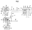
- a hydraulic auxiliary brake system has a brake pedal 2 which serves as an actuating device and which is connected to a master cylinder 4, for example a tandem master cylinder, which has two pressure chambers 6, 8. Furthermore, a brake caliper 10 serving as an application member is provided, which is provided with two piston-cylinder arrangements 12, 14. The first pressure chamber 6 of the master cylinder 4 is used for the hydraulic control of a throttle valve 16, which is flowed through by a pressure medium in power-assisted braking operation and is hydraulically connected to the first piston-cylinder arrangement 12 of the brake caliper 10.
- the throttle cross section of the throttle valve 16 can be set hydraulically to generate a defined dynamic pressure which is applied to the first piston-cylinder arrangement 12 of the brake caliper 10 in order to apply a braking force.
- the second pressure chamber 8 of the master cylinder 4 is hydraulically connected to the second piston-cylinder arrangement 14 of the brake caliper 10, so that a braking force can be applied to the brake caliper 10 even if the servo assistance fails.
- the brake pedal 2 is operatively connected via a piston rod 18 to a first piston 20 of the master cylinder 4, which hydraulically limits the first pressure chamber 6 on the brake pedal side.
- a second piston 22 is arranged between the first pressure chamber 6 and the second pressure chamber 8 and hydraulically separates the first and second pressure chambers 6, 8 from one another.
- the first and the second pressure chamber 6, 8 are each connected to an expansion tank 26 via a connection 24.
- the first pressure chamber 6 of the master cylinder 4 is connected via a control line 28 to a control chamber 30 of the throttle valve 16, which is designed as a three-chamber 2/2 ball seat valve with hydraulic control, which has an outlet chamber 32 and a pressure chamber 34 in addition to the control chamber 30.
- a valve body 36 in the form of a metallic ball is arranged in the outlet chamber 32 and can be acted upon mechanically with a force via an axially displaceable control piston 40 which extends sealingly through a wall 38 between the control chamber 30 and the outlet chamber 32.
- the valve body 36 can only be subjected to a compressive force via the control piston 40, since the valve body 36 and the control piston 40 are two separate components.
- a through hole 44 is provided in a wall 42 between the drain chamber 32 and the pressure chamber 34, which hydraulically connects the drain chamber 32 and the pressure chamber 34 to one another.
- An annular sealing seat 46 is attached to the through bore 44 on the discharge chamber side and, together with the valve body 36, delimits a valve gap 48, the flow cross section of which corresponds to the throttle cross section of the throttle valve 16.
- a return spring 50 is arranged in the pressure chamber 34, which extends through the through bore 44 and presses the valve body 36 against the control piston 40. If there is no control pressure in the control chamber 30, the control piston 40 is held in its initial position by the return spring 50 via the valve body 36, the valve gap 48 being opened to the maximum (zero passage position of the throttle valve 16).
- the pressure chamber 34 of the throttle valve 16 is hydraulically connected via a pressure line 52 to the outlet of a hydraulic pump 54, the input of which is preferably via a suction line 56 to a reservoir 58 for the pressure medium Brake fluid is connected.
- a check valve 60 is connected, which is biased towards the hydraulic pump 54.
- the drain chamber 32 of the throttle valve 16 is connected to the reservoir 58 via a return line 62.
- a pressure holding valve 64 is connected, which is biased towards the drain chamber 32.
- a pressure line 66 branches off from the pressure line 52 between the check valve 60 and the pressure chamber 34 of the throttle valve 16 and is connected to the pressure chamber 68 of the first piston-cylinder arrangement 12 of the brake caliper 10, so that the piston 70 of the first piston-cylinder The arrangement 12 can be acted upon by the dynamic pressure generated by the hydraulic pump 54 and controlled by the throttle valve 16.
- the second pressure chamber 8 of the master cylinder 4 is connected via a pressure line 72 directly to the pressure chamber 74 of the second piston-cylinder arrangement 14 of the brake caliper 10, so that the piston 76 of the second piston-cylinder arrangement 14 with the by depressing the brake pedal 2 can be applied via the second piston 22 of the master cylinder 4 pressure generated in the second pressure chamber 8.
- the brake caliper 10 in the illustrated case a floating caliper, is provided with brake pads 78 which, in a manner known per se, when the first or second piston-cylinder arrangement 12, 14 are pressurized by the piston 70 of the first piston-cylinder arrangement 12 or the piston 76 of the second piston-cylinder arrangement 14 is pressed against a brake disk 80.
- the first and the second piston-cylinder arrangement 12, 14 are arranged next to one another or parallel to one another, but they can also, for example be arranged concentrically or on opposite sides of the brake caliper 10 with respect to the brake disk 80.
- a pedal switch 82 that can be actuated mechanically via the brake pedal 2 and / or an electro-hydraulic pressure switch 84 connected into the control line 28 is provided, the function of which will be explained in the following.
- the hydraulic pump 54, the pressure line 52, the throttle valve 16 connected to the reservoir 58 via the return line 62, the pressure line 66 and the first piston-cylinder arrangement 12 of the brake caliper 10 form an external force brake circuit A, which is hydraulic separate control circuit C is actuated, which consists of the piston 20 of the master cylinder 4, the first pressure chamber 6 of the master cylinder 4, the control line 28, the control chamber 30 of the throttle valve 16 and the control piston 40 of the throttle valve 16, while the second piston 22 of the master cylinder 4, the second pressure chamber 8 of the master cylinder 4, the pressure line 72 and the second piston-cylinder arrangement 14 of the brake caliper 10 forms a brake circuit B which can be actuated manually via the brake pedal 2 independently of the external force brake circuit A.
- FIG. 1 Only a basic version of the auxiliary brake system with a brake caliper 10 for a wheel is shown in FIG. 1.
- the piston-cylinder arrangements of further brake calipers are via branch 66 'from the pressure line 66, which connects the pressure line 52 between the hydraulic pump 54 and pressure chamber 34 of the throttle valve 16 to the first piston-cylinder arrangement 12 in the brake caliper 10, or via the Branch 72 'of the pressure line 72 between the second pressure chamber 8 of the master cylinder 4 and the second piston-cylinder arrangement 14 of the Brake caliper 10 connected accordingly.
- the control pressure present in the control chamber 30 of the throttle valve 16 shifts the control piston 40 in FIG. 1 to the right and thus the valve body 36 resting on the control piston 40 by the force of the return spring 50 in the direction of the sealing seat 46.
- the hydraulic pump 54 via the pedal switch 82 operated by the brake pedal 2 or when a predetermined value is exceeded
- Signal pressure in the control circuit C started via the electro-hydraulic pressure switch 84, for which purpose the pedal switch 82 or the electro-hydraulic pressure switch 84 supplies an electrical signal that starts an electric motor (not shown) that is connected to the hydraulic pump 54 or an electromagnetic clutch (not shown) ) engages, which connects the hydraulic pump 54 to a rotating shaft of the engine or a wheel of the motor vehicle.
- the hydraulic pump 54 could also be operated during the entire service life of the motor vehicle.
- the hydraulic pump 54 now sucks the pressure medium from the reservoir 58 via the suction line 56 and conveys it via the check valve 60 and the pressure line 52 into the pressure chamber 34 of the throttle valve 16. From the pressure chamber 34, the pressure medium flows through the valve gap 48 into the outlet chamber 32 and from there via the return line 62 and the pressure holding valve 64 back into the reservoir 58. Since at the beginning of the actuation of the brake pedal 2 the control piston 40 of the throttle valve 16 and thus the valve body 36 are only slightly shifted in the direction of the sealing seat 46, so that the Valve gap 48 is almost completely open, the hydraulic pump 54 circulates the pressure medium largely without pressure via the throttle valve 16.
- valve body 36 is now pushed further via the hydraulically actuated control piston 40 against the force of the return spring 50 in the direction of the sealing seat 46, with a force that is equal to the product of the control pressure applied in the control chamber 30 by the master cylinder 4 and the hydraulic effective area of the control piston 40.
- the valve gap 48 decreases, as a result of which the flow cross-section for the flow through the hydraulic pump 54 increases Pressure line 52 and the pressure chamber 34 circulated pressure medium reduced.
- a dynamic pressure is generated in the external force brake circuit A in the direction of rotation of the pressure medium in front of the valve gap 48, which pressure propagates via the pressure chamber 34, the pressure line 52 and the pressure line 66 to the pressure chamber 68 of the first piston-cylinder arrangement 12 of the brake caliper 10 so that a braking force is applied to the brake disc 80 via the piston 70 of the first piston-cylinder arrangement 12 and the brake pads 78.
- the back pressure generated in front of the valve gap 48 essentially depends on the volume flow of the hydraulic pump 54 and the flow resistance of the throttle valve 16, but is, to a good approximation, proportional to the control pressure present in the control chamber 30 of the throttle valve 16.
- the proportionality factor between this control pressure and the dynamic pressure generated in front of the valve gap 48 is determined by the ratio of the hydraulic effective area of the control piston 40 in the control chamber 30 to the effective hydraulic effective area of the valve body 36 on the sealing seat 46.
- the desired pressure amplification can be achieved by appropriate dimensioning of these effective areas in the external brake circuit A.
- the reaction force applied to the effective hydraulic effective area of the valve body 36 by the dynamic pressure on the valve body 36 can be adjusted such that an appropriate feedback of the dynamic pressure is provided via the pressure column of the control circuit C between the control piston 40 of the throttle valve 16 and the first piston 20 of the master cylinder 4 to the brake pedal 2 in order to ensure a good pedal feel and thus to enable a sensitive actuation of the brake pedal 2. Since the valve gap 48 of the throttle valve 16 is continuously adjusted and not completely closed in the servo-assisted braking operation against the dynamic pressure is, in particular, there are no control pressure surges that could affect the brake pedal 2.
- the pressure generated in the second pressure chamber 8 of the master cylinder 4 by depressing the brake pedal 2 is simultaneously present in the brake chamber B in the pressure chamber 74 of the second piston-cylinder arrangement 14 of the brake caliper 10. This pressure thus also applies a braking force to the brake disc 80 via the piston 76 of the second piston-cylinder arrangement 14 and the brake linings 78.
- the reaction force generated on the piston 76 of the second piston-cylinder arrangement 14 becomes the reaction force in the control circuit via the pressure column between the piston 76 and the second piston 22 of the master cylinder 4 and the pressure column between the second piston 22 and the first piston 20 of the master cylinder 4 C superimposed reported back to the brake pedal 2, so that a sensitive actuation of the brake pedal 2 is possible taking into account the brake pressure actually prevailing in the brake caliper 10.
- the control pressure in the control circuit C is reduced by relieving the brake pedal 2 and the control piston 40 of the throttle valve 16 moves together with the valve body 36, enlarging the valve gap 48, into its starting position, counteracting the reducing control pressure in the control chamber 30 via the valve body 36 through the Increasing the valve gap 48, the dynamic pressure of the circulating pressure medium in the pressure chamber 34 becomes smaller and the force of the return spring 50 is loaded.
- the predetermined signal pressure in the control circuit C on the electro-hydraulic pressure switch 84 is undershot, the hydraulic pump 54 or its drive is possibly switched off and the circulation of the pressure medium is thus ended.
- brake circuit B the brake pressure in the pressure chamber 74 of the second piston-cylinder arrangement 14 naturally also decreases by relieving the brake pedal 2.
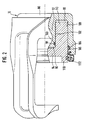
- FIG. 2 shows a brake caliper 10 for the brake system with a preferred design of the two piston-cylinder arrangements 12, 14, which can also be used in the first to third exemplary embodiments.
- annular chamber 88 is formed in a housing 86 of the brake caliper 10, in which a cup-shaped annular piston 90 is slidably received.
- the ring piston 90 is slidably in contact with a cylindrical pin 92 of the housing 86, which forms a cylindrical chamber 96 with the bottom 94 of the ring piston 90.
- Both the annular chamber 88 and the cylindrical chamber 96 are each provided with a connection (not shown), so that they can be connected to the pressure line 66 of the power brake circuit A or the pressure line 72 of the brake circuit B.
- the cylindrical chamber 96 is hydraulically sealed from the annular chamber 88 by means of a sealing element 98, which is received in a groove 100 in the outer peripheral surface 102 of the pin 92, but could also be fastened to the inner peripheral surface of the annular piston 90.
- the annular chamber 88 is sealed to the outside via a sealing element 104, which is received in a groove 106 in the inner peripheral surface 108 of the housing 86 is.
- the annular piston 90 is connected at its end portion 110 projecting from the housing 86 to the housing 86 via an elastic sleeve 112 which prevents brake dust from penetrating between the outer peripheral surface of the annular piston 90 and the inner peripheral surface 108 of the housing 86.
- the annular piston 90 interacts in a manner known per se via its end section 110 with brake pads (not shown) in order to apply a braking force to a brake disc (not shown).
- the housing 86 forms, together with the annular piston 90, the first and second piston-cylinder arrangements 12, 14 of the brake caliper 10 in a very compact design, so that the two-chamber brake caliper 10 does not require more installation space than a conventional single-chamber brake caliper.
- either the annular chamber 88 or the cylindrical chamber 96 is connected to the external brake circuit A via the pressure line 66, while the respective other chamber is connected to the brake circuit B via the pressure line 72.
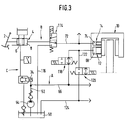
- the auxiliary brake system according to FIG. 1 is provided with further components in order to enable an anti-lock control (ABS). Parts corresponding to the parts in FIG. 1 are provided with the same reference symbols and are not explained again below.
- Fig. 3 shows the auxiliary brake system with ABS in the unactuated state.
- An anti-lock control basically has the effect that if a certain deceleration threshold is exceeded on a braked wheel, the wheel brake pressure is reduced until a second deceleration threshold on this wheel is undershot. For this it may be necessary to check the wheel brake pressure mine down to zero. The wheel brake pressure is then increased again until either the wheel in question is braked again or the brake pressure specified by the driver is reached.
- the manually controlled brake circuit B is provided with a relief valve 114, in the case shown an electromagnetically operable 3/2 way valve, which is switched into the pressure line 72 between the master cylinder 4 and the second piston-cylinder arrangement 14 of the brake caliper 10 and is connected to the reservoir 58 via a relief line 116.
- the relief valve 114 which is only present once in the system, optionally connects the pressure chamber 74 of the second piston-cylinder arrangement 14 to the second pressure chamber 8 of the master cylinder 4 or to the reservoir 58, and is in it the pressure chamber 74 of the second piston-cylinder arrangement 14 biased with the second pressure chamber 8 of the master cylinder 4 connecting position.
- the external force brake circuit A is provided with two switching valves 118, 120 for each wheel to be controlled, in the case shown electromagnetically actuated 2/2 way valves with a through and blocking position.
- the first switching valve 118 is connected in the pressure line 66 to the first piston-cylinder arrangement 12 of the brake caliper 10 and is pretensioned in such a way that, in its basic position, the pressure line 52 between the hydraulic pump 54 and the pressure chamber 34 of the throttle valve 16 with the pressure chamber 68 of the first Piston-cylinder assembly 12 connects.
- a line 122 branches off between the first switching valve 118 and the pressure chamber 68 of the first piston-cylinder arrangement 12, which leads into a collecting return line 124 connected to the storage container 58 or is connected directly to the storage container 58.
- the second switching valve 120 is switched into line 122 and biased into its closed position.
- a sensor system detects that the brake pressure applied via the external force brake circuit A or the brake circuit B in the brake caliper 10 is the braked wheel (not shown) ) blocking.
- the brake pressure is now suitably set by electromagnetic control of valves 114, 118 and 120.
- the relief valve 114 is switched into its position connecting the pressure chamber 74 of the second piston-cylinder arrangement 14 to the storage container 58, so that the pressure present is enclosed between the second pressure chamber 8 of the master cylinder 4 and the relief valve 114, while the brake pressure in the pressure chamber 74 of the second piston-cylinder arrangement 14 is reduced to zero via the relief line 116 to the reservoir 58.
- the brake pressure in the pressure chamber 68 of the first piston-cylinder arrangement 12 is reduced by switching the switching valves 118, 120, switching the first switching valve 118 from its open position to its blocking position via the hydraulic pump 54 and the like Throttle valve 16 generated dynamic pressure is blocked off from the pressure chamber 68 of the first piston-cylinder arrangement 12, while by switching the second switching valve 120 from its blocking position into its passage position, the pressure chamber 68 of the first piston-cylinder arrangement 12 is connected to the reservoir 58.
- the brake pressure in the pressure chamber 68 of the first piston-cylinder arrangement 12 is reduced towards the reservoir 54 until the deceleration threshold is undershot, so that the originally blocked wheel rotates again.
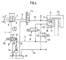
- the auxiliary brake system according to FIG. 1 or FIG. 3 is provided with further components in order to enable anti-slip control (ASR) and driving dynamics control. Parts corresponding to the parts in FIGS. 1 and 3 are provided with the same reference numerals and are not explained again below.
- Fig. 4 shows the auxiliary brake system with ASR or driving dynamics control in the unactuated state.
- an anti-slip control means that if, for example when starting a motor vehicle, the coefficients of friction of a driven wheel to the ground are too low, i.e. if an acceleration threshold is exceeded, this wheel is braked until a second acceleration threshold is undershot so that the wheel is in again a permissible slip range.
- a driving dynamics control which is based in principle on maintaining the longitudinal stability of the motor vehicle, measurable via the yaw angle between the longitudinal axis of the motor vehicle and the current direction of travel, the yaw moments that occur in critical driving conditions, such as understeering, oversteering or braking during fast cornering , which can lead to a breakaway or skidding of the motor vehicle, corrected, inter alia, by braking one or more wheels.
- the modulation of the brake pressure on individual wheels must therefore be possible. This is ensured with the help of the valves 118 and 120 described above, which are provided for each wheel, and an additional electromagnetic actuation of the throttle valve 16.
- the throttle valve 16 has an electromagnet 126 which can be controlled independently of the actuation of the brake pedal 2.
- the electromagnet 126 is operatively connected to the control piston 40 of the throttle valve 16, so that the control piston 40 can be displaced axially in a defined manner by actuating the electromagnet 126, for which purpose the electromagnet 126 is designed as a proportional magnet with a corresponding current-force characteristic.
- the control piston 40 can thus be displaceably shifted in a force-dependent manner via the electromagnet 126, the valve gap 48 of the throttle valve 16 decreasing when current is applied to the electromagnet 126 or increasing force and when the current is removed by the force of the return spring 50 of the throttle valve 16 and on the valve body 36 acting dynamic pressure is increased.
- the brake system is designed as a power brake system. Parts corresponding to the parts in FIG. 1 are provided with the same reference symbols and are not explained again below.
- Fig. 5 shows the power brake system in the unactuated state.
- control circuit C thus corresponds in structure and function to that of the exemplary embodiments described above and therefore does not need to be described again in detail.
- the dynamic pressure generated in the throttle valve 16 is applied in order to apply a braking force to a piston-cylinder arrangement 12 'of an application element hydraulically connected to the throttle valve 16 in the servo-force braking mode, in the form of a brake caliper 10', which, in contrast to the previously described exemplary embodiments, has only one piston -Cylinder arrangement 12 '.
- the brake caliper 10 ' shown in In the case of a floating caliper, as in the previously described exemplary embodiments, it is provided with brake pads 78 which, in a manner known per se, are pressed against the brake disk 80 by the piston 70 'when the pressure chamber 68' of the piston-cylinder arrangement 12 'is pressurized.
- an additional separating piston-cylinder arrangement 150 is provided, the separating piston 152 of which is a servo pressure chamber 154 on the right in FIG. 5 from the separating piston 152 and on the left in FIG. 5 hydraulically separates actuating pressure chamber 156 from the separating piston 152.
- the servo pressure chamber 154 is hydraulically connected to the piston-cylinder arrangement 12 'of the brake caliper 10' via a pressure line 158, while the actuating pressure chamber 156 is hydraulically connected to the second pressure chamber 8 of the master cylinder 4 via the pressure line 72, so that even if the External brake circuit A can be applied to the brake caliper 10 'by the hydraulic pressure present in the pressure line 72 of the brake circuit B and thus in the actuating pressure chamber 156 of the separating piston-cylinder arrangement 150 via the separating piston 152 on the brake caliper 10', as described in more detail below becomes.
- the separating piston-cylinder arrangement 150 has in particular a preferably cylindrical housing 160 with a cylinder bore 162 in which the separating piston 152, which can be acted upon from two sides, is accommodated in a longitudinally displaceable manner.
- a connection 164 is provided for the pressure line 158 leading to the piston-cylinder arrangement 12 ′ and on the left end side of the housing 160 in FIG. 5
- a connection 166 is provided for the master cylinder 4 leading pressure line 72 formed while on the circumference of the Housing 160 approximately in the middle
- a connection 168 is provided for the pressure line 66 leading to the throttle valve 16.
- the separating piston 152 has a section of reduced diameter lying approximately centrally in the axial direction, which delimits a further pressure chamber 170 with the cylinder bore 162 and the larger-diameter sections of the separating piston 152 lying on both sides of the central section.
- the further pressure chamber 170 is hydraulically separated from the servo pressure chamber 154 or the actuation pressure chamber 156 to the right or left in FIG. 5 by means of sealing elements 172, such as O-rings, provided in the circumferential grooves of the larger diameter sections of the separating piston 152.
- the separating piston 152 has a central valve 174 known per se in the brake hydraulics and is biased into the actuating pressure chamber 156 by means of a return spring 176 accommodated in the servo pressure chamber 154.
- the central central valve 174 has a valve sealing body 180 connected to a valve tappet 178, which is prestressed by means of a valve spring 182 against a sealing seat 184 worked on the separating piston 152 in the direction of the actuating pressure chamber 156.
- the separating piston 152 is provided with a recess 186 which is penetrated by a stop 188 attached to the inner peripheral wall of the housing 160.
- the separating piston 152 is biased against the stop 188 by the force of the return spring 176.
- the valve tappet 178 bears against the stop 188, as a result of which the valve sealing body 180 is spaced apart from the sealing seat 184 on the separating piston 152 via the valve tappet 178 against the force of the valve spring 182 is held so that the central valve 174 is opened.
- the further pressure chamber 170 of the separating piston-cylinder arrangement 150 is hydraulically connected to its servo pressure chamber 154 via the opened central valve 174, so that during operation the servo pressure in the pressure line 66 in the external force brake circuit A via the additional pressure chamber 170 of the separating piston Cylinder arrangement 150, the open central valve 174, the servo pressure chamber 154 and the pressure line 158 abut against the piston-cylinder arrangement 12 'of the brake caliper 10', while in the brake circuit B the second piston 22 of the master cylinder 4 via the second pressure chamber 8 of the master cylinder 4, the pressure line 72 and the actuation pressure chamber 156 of the separating piston-cylinder arrangement 150 are hydraulically operatively connected to the separating piston 152.
- the mode of operation of the fourth exemplary embodiment is described below insofar as it differs from that of the first exemplary embodiment described with reference to FIG. 1.
- the valve gap 48 of the throttle valve 16 is set via the control circuit C as described with reference to FIG. 1 as a function of the pressure generated in the first pressure chamber 6 of the master cylinder 4 when the brake pedal 2 is depressed.
- the dynamic pressure generated when the hydraulic pump 54 is flowing through the valve gap 48 in the throttle valve 16 is via the pressure line 66 of the external force brake circuit A, the connection 168 of the separating piston-cylinder arrangement 150, the further pressure chamber 170, the open central valve 174, the servo pressure chamber 154 , the connection 164 and the pressure line 158 in the piston-cylinder arrangement 12 'of the brake caliper 10'.
- the pressure generated in the second pressure chamber 8 of the master cylinder 4 is present in the actuating pressure chamber 156 via the pressure line 72 of the brake circuit B and the connection 166 of the separating piston-cylinder arrangement 150.
- the separating piston 152 remains due to the essentially simultaneous pressurization of the pressure lines 66, 72 or the pressure build-up running behind in the brake circuit B compared to the power brake circuit A in its basic position shown in FIG. 5 at the stop 188.
- the prerequisite for this is that the hydraulic effective surfaces of the separating piston 152 and / or the operating pressure level in the control circuit C or brake circuit B are selected in comparison to that of the external force brake circuit A such that the forces acting on the separating piston 152 cancel each other out or the resulting force in the direction of the actuation pressure chamber 156 acts, smaller differences being compensated for by the biasing force of the return spring 176.
- the braking force is applied to the brake disc 80 solely by the back pressure generated in the throttle valve 16 via the piston-cylinder arrangement 12 'of the brake caliper 10', with adequate feedback via the pressure column of the control circuit C between the throttle valve 16 and the master cylinder 4 of the dynamic pressure to the brake pedal 2 takes place, which allows a sensitive actuation of the brake pedal 2.
- the pressure present in the actuating pressure chamber 156 when the brake pedal 2 is depressed shifts the pressure Separating piston 152 against the force of the return spring 176 from its basic position away from the stop 188 into the servo pressure chamber 154.
- the valve tappet 178 is released from the stop 188 so that the valve sealing body 180 is pressed against the sealing seat 184 by the valve spring 182. Accordingly, the now closed central valve 174 hydraulically separates the further pressure chamber 170 from the servo pressure chamber 154.
- the required auxiliary brake pressure builds up in the servo pressure chamber 154 as a result of the displacement of the separating piston 152, which is applied via the connection 164 and the pressure line 158 to the piston-cylinder arrangement 12 'of the brake caliper 10' in order to apply a braking force to the auxiliary brake Apply brake disc 80.
- the separating piston 152 is shifted further to the right in FIG. 5, the separating piston 152 abuts the stop 188 at the end of the recess 186, which thus limits the auxiliary brake pressure to a maximum value and prevents the central valve 174 from hitting the bottom of the housing 160 .
- the reaction force generated during auxiliary braking on the piston 70 'of the piston-cylinder arrangement 12' of the brake caliper 10 ' is reported back to the brake pedal 2 via the pressure column between the piston 70 'and the separating piston 152 and the pressure column between the separating piston 152 and the second piston 22 of the master cylinder 4, so that sensitive braking of the brake pedal 2 is also taken into account during auxiliary braking, taking into account the actually in the brake caliper 10 'prevailing brake pressure is possible.
- the reservoir 58 for the pressure medium which is separate from the expansion tank 26 of the master cylinder 4, is preferably provided with a fill level monitor 190, which is connected to the control of the drive of the hydraulic pump 54, such as an electric motor or an electromagnetic clutch (not shown). If there is a mechanically induced pressure drop, for example due to the bursting of the pressure line 66 or the pressure line 158, the decrease in the pressure medium in the reservoir 58 caused while the hydraulic pump 54 is running is detected by the fill level monitor 190. The drive of the hydraulic pump 54 is then switched off in dependence on a fill level signal generated by the fill level monitor 190 in order to prevent the reservoir 58 from being emptied.
- a fill level monitor 190 which is connected to the control of the drive of the hydraulic pump 54, such as an electric motor or an electromagnetic clutch (not shown). If there is a mechanically induced pressure drop, for example due to the bursting of the pressure line 66 or the pressure line 158, the decrease in the pressure medium in the reservoir 58 caused while the hydraulic pump 54 is running is
- auxiliary braking via the brake circuit B can be carried out by the further functional application elements (not shown), ie the brake calipers or Wheel brake cylinders, which are connected via branch 72 '.
- the brake circuit B like the control circuit C, is expediently supplied with pressure medium via the expansion tank 26 provided on the master cylinder 4, independently of the reservoir 58.
- FIG. 6A shows a first variant 150 'of the separating piston-cylinder arrangement 150 described with reference to FIG. 5, which can be used instead of the separating piston-cylinder arrangement 150 according to FIG. 5.
- the separating piston-cylinder arrangement 150 ' differs from the separating piston-cylinder arrangement 150 shown in FIG. 5 in that no central valve is provided in the separating piston 152', so that the separating piston-cylinder arrangement 150 'is more economical can be trained.
- the connection 168 ' is mounted in the peripheral wall of the housing 160' in such a way that the pressure line 66 is hydraulically connected directly to the servo pressure chamber 154 when the separating piston 152 'is biased in the basic position by means of the return spring 176.
- FIG. 6B shows an economical second variant 150 ′′ of the separating piston-cylinder arrangement 150 described with reference to FIG. 5, which can be used instead of the separating piston-cylinder arrangement 150 or 150 ′.
- the separating piston-cylinder arrangement 150 ′′ according to FIG. 6B likewise has no central valve in the separating piston 152 ′′ and differs from the separating piston-cylinder arrangement 150 ′ shown in FIG. 6A in that in the peripheral wall of the housing 160 '' No connection is provided for the pressure line 66 and the separating piston 152 '' can be formed without an additional pressure chamber.
- the pressure line 66 is connected directly to the pressure line 158. Accordingly, since the separating piston-cylinder arrangement 150 ′′ cannot separate the pressure line 66 from the pressure line 158, no auxiliary braking can take place via the brake caliper 10 ′ assigned to the separating piston-cylinder arrangement 150 ′′ if pressure medium is lost in the external force brake circuit A.
- auxiliary braking must take place via the brake circuit B by the further functional application elements which are connected via the branch 72 '. If the control circuit C or the hydraulic pump 54 fails without loss of pressure medium in the external force brake circuit A, however, auxiliary braking is possible as described above via the separating piston-cylinder arrangement 150 ′′.
- the power brake system according to FIG. 5 is provided with further components in order to enable an anti-lock control (ABS). 1, 3 and 5 corresponding parts are provided with the same reference numerals and will not be explained again below.
- Fig. 7 shows the power brake system with ABS in the unactuated state.
- the fifth exemplary embodiment according to FIG. 7 is provided with a relief valve 114 in the brake circuit B, which is connected to the pressure line 72 between the master cylinder 4 and the separating piston-cylinder arrangement 150 ′′ and via a relief line 116 to the reservoir 58 is connected.
- the relief valve 114 is only present once in the brake system.
- the relief valve 114 optionally connects the actuation pressure chamber 156 of the separating piston-cylinder arrangement 150 ′′ to the second pressure chamber 8 of the master cylinder 4 or to the reservoir 58, in which it actuates the actuation pressure chamber 156 of the separating piston-cylinder arrangement 150 ′′ to the second Pressure chamber 8 of the master cylinder 4 connecting position is biased.
- the external power brake circuit A is further provided with two switching valves 118, 120 for each wheel to be controlled, as in the second exemplary embodiment.
- the first switching valve 118 is connected in the pressure line 66 to the piston-cylinder arrangement 12 'of the brake caliper 10' and is pretensioned such that in its basic position it connects the pressure line 52 between the hydraulic pump 54 and the throttle valve 16 with the pressure line 158 between the separating piston Cylinder arrangement 150 '' and the piston-cylinder arrangement 12 'of the brake caliper 10' connects.
- a line 122 branches off between the first switching valve 118 and the pressure line 158 and ends in a collecting return line 124 connected to the storage container 58.
- the second switching valve 120 is connected in the line 122 and biased into its closed position.
- a sensor system detects that the brake pressure applied via the external force brake circuit A or the brake circuit B in the brake caliper 10 'is the braked wheel (not shown) ) blocking.
- the brake pressure is now suitably set by electromagnetic control of valves 114, 118 and 120.
- the relief valve 114 is inserted into the actuating pressure chamber 156 of the separating piston-cylinder arrangement 150 ′′ the reservoir 58 connecting position switched so that the pressure present between the second pressure chamber 8 of the master cylinder 4 and the relief valve 114 is enclosed, while the pressure in the actuating pressure chamber 156 is reduced to zero via the relief line 116 to the reservoir 58, so that the Separating piston 152 '' remains in its basic position.
- the brake pressure which is present in the pressure chamber 68 'of the piston-cylinder arrangement 12' of the brake caliper 10 ' is reduced by switching the switching valves 118, 120.
- the dynamic pressure generated by means of the hydraulic pump 54 and the throttle valve 16 is blocked by switching the first switching valve 118 from its through position into its blocking position with respect to the pressure chamber 68 'of the piston-cylinder arrangement 12', while the pressure chamber 68 'is switched by switching the second switching valve 120 is connected from its locked position to its through position with the reservoir 58.
- the brake pressure in the pressure chamber 68 ' is reduced until the deceleration threshold is undershot, at which the originally blocked wheel rotates again.
- valves 114, 118 and 120 are no longer controlled electromagnetically, so that they each return to their prestressed basic position and in the brake caliper 10 'as described with reference to FIG. 5 by the external force brake circuit A. braking force proportional to the actuating force is applied.
- each individual clamping element is secured regardless of the brake force distribution so that if it fails, the remaining clamping elements remain fully functional. If the hydraulic pump 54 fails, the auxiliary braking is effected via the brake circuit B, as described with reference to FIG. 5.
- the hydraulic pump 54 cannot be switched off if a movement of the separating pistons 152 ′′ of the separating piston-cylinder arrangements 150 ′′ can be sensed by means of an activation contact or sensor (not shown).
- the brake system shown in FIG. 7 has the variant 150 ′′ of the separating piston-cylinder arrangement shown in FIG. 6B, but the separating piston-cylinder arrangement shown in FIG. 5 or 6A could equally well 150 or 150 'are used.
- a plurality of clamping elements 10 ' for example an axis circle or a diagonal circle via the pressure line 158 or its branch 158', are on a separating piston-cylinder arrangement 150 is connected in order to jointly secure the corresponding application members 10 'against a failure of the servo pressure.
- the variants 150 ′ or 150 ′′ can be used instead of the separating piston-cylinder arrangement 150.
- Two switching valves 118, 120 are further provided for each application element 10 ', of which the switching valve 118 enters the pressure line 158 between the servo pressure chamber 154 of the separating piston-cylinder arrangement 150 and the pressure chamber 68' of the piston-cylinder arrangement 12 'of the application element 10 ', that is, seen from the throttle valve 16 or the hydraulic pump 54, is connected behind the separating piston-cylinder arrangement 150.
- the relief valve provided according to FIG. 7 can be dispensed with because the separating piston 152 of the separating piston-cylinder arrangement 150 is acted upon by the dynamic pressure generated in the throttle valve 16 even during the anti-lock control and accordingly remains in its basic position.
- FIG. 9 shows a second variant of the fifth exemplary embodiment, which is described below only with regard to its features that differ from the first variant of the fifth exemplary embodiment according to FIG. 8.
- a second separating piston-cylinder arrangement 150.2 connected in parallel therewith is provided, so that the clamping elements 10 'of each circle, i.e. of each axis or diagonal circuit are jointly secured against failure of the servo pressure.
- the second separating piston-cylinder arrangement 150.2 is connected with its actuating pressure chamber 156 to the branch 72 'from the pressure line 72, while the servo pressure chamber 154 of the second separating piston-cylinder arrangement 150.2 is hydraulically connected to the pressure line 66 via the branch 66'.
- a brake system which has a manually actuated master cylinder with two pressure chambers.
- the first pressure chamber is used for the hydraulic control of a pressure medium through which the pressure medium flows in a servo force braking mode Throttle valve, in order to adjust its throttle cross section to generate a defined dynamic pressure, which is applied to a first piston-cylinder arrangement of an application element connected to the throttle valve for applying a braking force.
- the second pressure chamber can be connected to a second piston-cylinder arrangement of the application element, so that a braking force can be applied if the servo force fails.
- a separate separating piston-cylinder arrangement can also be provided, which is connected between the second pressure chamber and the piston-cylinder arrangement.
Landscapes
- Engineering & Computer Science (AREA)
- Physics & Mathematics (AREA)
- Fluid Mechanics (AREA)
- Mechanical Engineering (AREA)
- Transportation (AREA)
- General Engineering & Computer Science (AREA)
- Regulating Braking Force (AREA)
- Braking Systems And Boosters (AREA)
Priority Applications (1)
| Application Number | Priority Date | Filing Date | Title |
|---|---|---|---|
| EP99116531A EP0955222B1 (fr) | 1995-09-12 | 1996-09-07 | Système de freinage hydraulique, notamment pour véhicules |
Applications Claiming Priority (4)
| Application Number | Priority Date | Filing Date | Title |
|---|---|---|---|
| DE19533481 | 1995-09-12 | ||
| DE19533481 | 1995-09-12 | ||
| DE19618489 | 1996-05-08 | ||
| DE19618489A DE19618489C2 (de) | 1995-09-12 | 1996-05-08 | Hydraulische Bremsanlage, insbesondere für Kraftfahrzeuge |
Related Child Applications (1)
| Application Number | Title | Priority Date | Filing Date |
|---|---|---|---|
| EP99116531A Division EP0955222B1 (fr) | 1995-09-12 | 1996-09-07 | Système de freinage hydraulique, notamment pour véhicules |
Publications (3)
| Publication Number | Publication Date |
|---|---|
| EP0761519A2 true EP0761519A2 (fr) | 1997-03-12 |
| EP0761519A3 EP0761519A3 (fr) | 1997-03-26 |
| EP0761519B1 EP0761519B1 (fr) | 2001-12-12 |
Family
ID=26018445
Family Applications (1)
| Application Number | Title | Priority Date | Filing Date |
|---|---|---|---|
| EP96114352A Expired - Lifetime EP0761519B1 (fr) | 1995-09-12 | 1996-09-07 | Système de freinage hydraulique pour véhicules |
Country Status (3)
| Country | Link |
|---|---|
| US (2) | US5700067A (fr) |
| EP (1) | EP0761519B1 (fr) |
| JP (1) | JPH09169261A (fr) |
Cited By (1)
| Publication number | Priority date | Publication date | Assignee | Title |
|---|---|---|---|---|
| WO2001025068A1 (fr) * | 1999-10-02 | 2001-04-12 | Daimlerchrysler Ag | Systeme de freinage pour vehicule avec amplification electro-hydraulique de la puissance de freinage |
Families Citing this family (24)
| Publication number | Priority date | Publication date | Assignee | Title |
|---|---|---|---|---|
| EP0761519B1 (fr) * | 1995-09-12 | 2001-12-12 | FTE automotive GmbH | Système de freinage hydraulique pour véhicules |
| DE19653308B4 (de) * | 1996-12-20 | 2010-04-15 | Robert Bosch Gmbh | Hydraulische Fahrzeugbremsanlage |
| US5971502A (en) * | 1998-06-04 | 1999-10-26 | Robert Bosch Technology Corp | Secondary braking control |
| US6390566B1 (en) * | 1999-05-25 | 2002-05-21 | Nissin Kogyo Co., Ltd. | Vehicle braking system |
| GB9916255D0 (en) * | 1999-07-12 | 1999-09-15 | Ford New Holland Nv | Apparatus and method for positioning steerable wheels |
| JP2001107998A (ja) * | 1999-10-08 | 2001-04-17 | Nisshinbo Ind Inc | ディスクブレーキのシリンダ装置 |
| JP4271801B2 (ja) * | 1999-11-19 | 2009-06-03 | 茂 長野 | 車輪のブレーキ制御装置 |
| CA2392215A1 (fr) * | 1999-11-24 | 2001-05-31 | William Lunceford Barnett | Systeme de frein hydraulique de vehicules |
| JP4320968B2 (ja) * | 2000-05-02 | 2009-08-26 | トヨタ自動車株式会社 | ブレーキシステム |
| GB0016271D0 (en) * | 2000-07-04 | 2000-08-23 | Meritor Automotive Inc | Vehicle braking systems |
| US6953229B2 (en) | 2000-12-28 | 2005-10-11 | Toyota Jidosha Kabushiki Kaisha | Hydraulic braking system and method with flow control device |
| US6923296B1 (en) | 2004-03-05 | 2005-08-02 | Robert Bosch Corporation | Disc Brake |
| US7499785B2 (en) * | 2004-10-22 | 2009-03-03 | Delphi Technologies, Inc. | Extended braking compensation in hybrid braking systems |
| US7344199B2 (en) * | 2005-03-15 | 2008-03-18 | Deere & Company | Primary/secondary brake system |
| US20080087504A1 (en) * | 2006-10-13 | 2008-04-17 | Jacob Kobelt | Roller housing having retaining arms |
| US7857109B2 (en) * | 2006-10-13 | 2010-12-28 | Interkob Holdings Ltd. | Adjustable cam actuated brake assembly |
| DE102007016250A1 (de) * | 2006-12-12 | 2008-06-19 | Robert Bosch Gmbh | Scheibenbremse |
| JP4890378B2 (ja) * | 2007-07-31 | 2012-03-07 | 日立オートモティブシステムズ株式会社 | ブレーキ装置 |
| JP4609462B2 (ja) * | 2007-08-10 | 2011-01-12 | トヨタ自動車株式会社 | ブレーキ制御装置 |
| GB2463648A (en) | 2008-09-18 | 2010-03-24 | Valtra Oy Ab | Braking system having a dual slave cylinder arrangement |
| CN103453054B (zh) * | 2012-05-31 | 2017-06-30 | 林立 | 一种盘刹系统和控制所述盘刹系统的方法 |
| CN103615480B (zh) * | 2013-11-25 | 2015-09-30 | 湘潭市恒欣实业有限公司 | 双泵驱动安全制动液压控制系统 |
| CN107061566B (zh) * | 2017-05-23 | 2018-10-19 | 北京航空航天大学 | 一种功率电传飞机刹车装置 |
| CN109835321B (zh) * | 2017-11-28 | 2021-11-05 | 中冶宝钢技术服务有限公司 | 履带式装载机液压驻车制动解除方法 |
Citations (9)
| Publication number | Priority date | Publication date | Assignee | Title |
|---|---|---|---|---|
| DE2450874A1 (de) * | 1973-10-25 | 1975-05-15 | Dewandre Co Ltd C | Hydraulisches bremssystem |
| EP0169178A2 (fr) * | 1984-07-11 | 1986-01-22 | FIAT AUTO S.p.A. | Etrier de sécurité pour un frein à disque de véhicules à moteur |
| DE3538330A1 (de) * | 1985-10-28 | 1987-04-30 | Teves Gmbh Alfred | Hydraulische bremsanlage fuer kraftfahrzeuge |
| DE3626292A1 (de) * | 1986-08-02 | 1988-02-11 | Teves Gmbh Alfred | Hydraulische bremsanlage fuer kraftfahrzeuge |
| DE3627809A1 (de) * | 1986-08-16 | 1988-02-18 | Teves Gmbh Alfred | Hydraulische bremsanlage mit blockierschutz- und/oder antriebsschlupfregelung |
| EP0265623A2 (fr) * | 1986-09-04 | 1988-05-04 | Sumitomo Electric Industries, Ltd. | Appareil de contrôle de freinage pour véhicules |
| DE3638510A1 (de) * | 1986-11-11 | 1988-05-19 | Teves Gmbh Alfred | Bremsanlage mit schlupfregelung |
| DE3705311A1 (de) * | 1987-02-19 | 1988-09-01 | Teves Gmbh Alfred | Hydraulische bremsanlage fuer kraftfahrzeuge |
| DE3744070A1 (de) * | 1987-12-24 | 1989-07-06 | Teves Gmbh Alfred | Blockiergeschuetzte hydraulische bremsanlage |
Family Cites Families (17)
| Publication number | Priority date | Publication date | Assignee | Title |
|---|---|---|---|---|
| DE1037287B (de) * | 1952-10-02 | 1958-08-21 | Teves Kg Alfred | Hydraulische Bremsbetaetigungsvorrichtung mit Hilfskraftpumpe, insbesondere fuer Kraftfahrzeuge |
| DE1134904B (de) * | 1955-06-01 | 1962-08-16 | Dunlop Rubber Co | Mit einem Hauptzylinder kombiniertes Bremsventil fuer eine insbesondere fuer Kraftfahrzeuge vorgesehene hydraulische Bremsbetaetigungsanlage |
| US2932947A (en) * | 1957-12-26 | 1960-04-19 | Westinghouse Air Brake Co | Hydraulic power brake apparatus |
| DE2933085A1 (de) * | 1979-08-16 | 1981-02-26 | Bosch Gmbh Robert | Antiblockierregelsystem |
| DE3247496A1 (de) * | 1982-12-22 | 1984-06-28 | Alfred Teves Gmbh, 6000 Frankfurt | Hydraulische zweikreisbremsanlage |
| DE3427380A1 (de) * | 1984-07-25 | 1986-01-30 | Alfred Teves Gmbh, 6000 Frankfurt | Bremsdruckgeber fuer schlupfgeregelte kraftfahrzeug-bremsanlagen |
| DE3526556A1 (de) * | 1985-07-25 | 1987-01-29 | Teves Gmbh Alfred | Bremsanlage mit hydraulischer bremskraftverstaerkung |
| DE3603074A1 (de) * | 1985-08-24 | 1987-03-05 | Kugelfischer G Schaefer & Co | Elektromagnetisch betreibbarer druckmodulator |
| DE3702573A1 (de) * | 1987-01-29 | 1988-08-11 | Kugelfischer G Schaefer & Co | Elektromagnetisch betaetigter druckmodulator |
| DE3723875A1 (de) * | 1987-07-18 | 1989-02-02 | Daimler Benz Ag | Sicherheitseinrichtung fuer ein mit einem antiblockiersystem ausgeruestetes strassenfahrzeug |
| DE3905044C2 (de) * | 1989-02-18 | 1997-09-11 | Teves Gmbh Alfred | Kraftfahrzeugbremsanlage mit Blockier- und/oder Antriebsschlupfregelung |
| DE3933797A1 (de) * | 1989-10-10 | 1991-04-18 | Bosch Gmbh Robert | Bremsanlage |
| IT1240023B (it) * | 1990-04-30 | 1993-11-27 | Alfa Lancia Spa | Impianto frenante a doppia pinza |
| DE4322292A1 (de) * | 1993-07-05 | 1995-01-12 | Teves Gmbh Alfred | Vorrichtung zur Erzeugung einer Bremskraft für eine Kraftfahrzeugbremsanlage |
| JP3216371B2 (ja) * | 1993-11-18 | 2001-10-09 | トヨタ自動車株式会社 | 液圧制御機構およびそれを用いた車両用ブレーキ装置 |
| DE4344580C2 (de) * | 1993-12-24 | 1996-03-28 | Daimler Benz Ag | Ventilanordnung für die Bremsdrucksteuerung bei einer hydraulischen Hilfskraftbremsanlage eines Straßenfahrzeuges |
| EP0761519B1 (fr) * | 1995-09-12 | 2001-12-12 | FTE automotive GmbH | Système de freinage hydraulique pour véhicules |
-
1996
- 1996-09-07 EP EP96114352A patent/EP0761519B1/fr not_active Expired - Lifetime
- 1996-09-09 US US08/707,886 patent/US5700067A/en not_active Expired - Fee Related
- 1996-09-12 JP JP8242232A patent/JPH09169261A/ja active Pending
-
1997
- 1997-07-28 US US08/901,716 patent/US5826953A/en not_active Expired - Lifetime
Patent Citations (9)
| Publication number | Priority date | Publication date | Assignee | Title |
|---|---|---|---|---|
| DE2450874A1 (de) * | 1973-10-25 | 1975-05-15 | Dewandre Co Ltd C | Hydraulisches bremssystem |
| EP0169178A2 (fr) * | 1984-07-11 | 1986-01-22 | FIAT AUTO S.p.A. | Etrier de sécurité pour un frein à disque de véhicules à moteur |
| DE3538330A1 (de) * | 1985-10-28 | 1987-04-30 | Teves Gmbh Alfred | Hydraulische bremsanlage fuer kraftfahrzeuge |
| DE3626292A1 (de) * | 1986-08-02 | 1988-02-11 | Teves Gmbh Alfred | Hydraulische bremsanlage fuer kraftfahrzeuge |
| DE3627809A1 (de) * | 1986-08-16 | 1988-02-18 | Teves Gmbh Alfred | Hydraulische bremsanlage mit blockierschutz- und/oder antriebsschlupfregelung |
| EP0265623A2 (fr) * | 1986-09-04 | 1988-05-04 | Sumitomo Electric Industries, Ltd. | Appareil de contrôle de freinage pour véhicules |
| DE3638510A1 (de) * | 1986-11-11 | 1988-05-19 | Teves Gmbh Alfred | Bremsanlage mit schlupfregelung |
| DE3705311A1 (de) * | 1987-02-19 | 1988-09-01 | Teves Gmbh Alfred | Hydraulische bremsanlage fuer kraftfahrzeuge |
| DE3744070A1 (de) * | 1987-12-24 | 1989-07-06 | Teves Gmbh Alfred | Blockiergeschuetzte hydraulische bremsanlage |
Cited By (1)
| Publication number | Priority date | Publication date | Assignee | Title |
|---|---|---|---|---|
| WO2001025068A1 (fr) * | 1999-10-02 | 2001-04-12 | Daimlerchrysler Ag | Systeme de freinage pour vehicule avec amplification electro-hydraulique de la puissance de freinage |
Also Published As
| Publication number | Publication date |
|---|---|
| EP0761519A3 (fr) | 1997-03-26 |
| EP0761519B1 (fr) | 2001-12-12 |
| US5826953A (en) | 1998-10-27 |
| JPH09169261A (ja) | 1997-06-30 |
| US5700067A (en) | 1997-12-23 |
Similar Documents
| Publication | Publication Date | Title |
|---|---|---|
| EP0761519B1 (fr) | Système de freinage hydraulique pour véhicules | |
| EP1926644B1 (fr) | Systeme de freinage pour vehicules automobiles | |
| WO2019197555A1 (fr) | Système de freinage hydraulique de véhicule et procédé pour le faire fonctionner | |
| DE2443545C2 (de) | Bremsanlage mit Antiblockierregelung | |
| WO2019197550A1 (fr) | Système de freinage hydraulique de véhicule et procédé pour le faire fonctionner | |
| WO2019197561A1 (fr) | Système de freinage hydraulique de véhicule et procédé pour le faire fonctionner | |
| EP2643195B1 (fr) | Système de freinage pour véhicules à moteur | |
| WO1996020102A1 (fr) | Systeme hydraulique de freinage pour vehicules a moteur | |
| EP0761520B1 (fr) | Arrangement de soupapes pour circuit de freinage assisté d'un système de freinage hydraulique | |
| WO2006061279A1 (fr) | Systeme de freinage pour vehicule, actionnable par fluide hydraulique et procede de commande d'un systeme de freinage pour vehicule, actionnable par fluide hydraulique | |
| EP0722397B1 (fr) | Systeme de freinage pour vehicules automobiles | |
| WO1998057833A1 (fr) | Systeme d'actionnement des freins a regulation electronique | |
| DE2942979C2 (fr) | ||
| EP0955222B1 (fr) | Système de freinage hydraulique, notamment pour véhicules | |
| EP0898532B1 (fr) | Dispositif maitre-cylindre pour un systeme de freinage hydraulique de vehicule | |
| DE102017207182A1 (de) | Hauptbremszylinder und Bremsanlage mit einem solchen Hauptbremszylinder | |
| DE3832722A1 (de) | Bremsanlage | |
| DE19932670C2 (de) | Hauptzylinderanordnung | |
| WO2003033323A1 (fr) | Systeme de freinage electrohydraulique destine a des vehicules automobiles | |
| DE3542601A1 (de) | Schlupfgeregelte bremsanlage | |
| DE2620613A1 (de) | Hydraulische bremsanlage mit blockierschutzeinrichtung fuer fahrzeuge | |
| WO2003053755A1 (fr) | Systeme de freinage electro-hydraulique pour automobiles | |
| DE10304145A1 (de) | Elektrohydraulische Fahrzeugbremsanlage | |
| DE10240692A1 (de) | Elektrohydraulische Bremsanlage für Kraftfahrzeuge | |
| EP1305195B1 (fr) | Système de freinage hydraulique pour véhicule |
Legal Events
| Date | Code | Title | Description |
|---|---|---|---|
| PUAI | Public reference made under article 153(3) epc to a published international application that has entered the european phase |
Free format text: ORIGINAL CODE: 0009012 |
|
| PUAL | Search report despatched |
Free format text: ORIGINAL CODE: 0009013 |
|
| AK | Designated contracting states |
Kind code of ref document: A2 Designated state(s): DE FR GB IT |
|
| AK | Designated contracting states |
Kind code of ref document: A3 Designated state(s): DE FR GB IT |
|
| 17P | Request for examination filed |
Effective date: 19970829 |
|
| 17Q | First examination report despatched |
Effective date: 19990609 |
|
| RAP1 | Party data changed (applicant data changed or rights of an application transferred) |
Owner name: FTE AUTOMOTIVE GMBH |
|
| GRAG | Despatch of communication of intention to grant |
Free format text: ORIGINAL CODE: EPIDOS AGRA |
|
| GRAG | Despatch of communication of intention to grant |
Free format text: ORIGINAL CODE: EPIDOS AGRA |
|
| GRAH | Despatch of communication of intention to grant a patent |
Free format text: ORIGINAL CODE: EPIDOS IGRA |
|
| GRAH | Despatch of communication of intention to grant a patent |
Free format text: ORIGINAL CODE: EPIDOS IGRA |
|
| GRAA | (expected) grant |
Free format text: ORIGINAL CODE: 0009210 |
|
| AK | Designated contracting states |
Kind code of ref document: B1 Designated state(s): DE FR GB IT |
|
| REG | Reference to a national code |
Ref country code: GB Ref legal event code: IF02 |
|
| GBT | Gb: translation of ep patent filed (gb section 77(6)(a)/1977) |
Effective date: 20011212 |
|
| REF | Corresponds to: |
Ref document number: 59608421 Country of ref document: DE Date of ref document: 20020124 |
|
| ET | Fr: translation filed | ||
| PLBE | No opposition filed within time limit |
Free format text: ORIGINAL CODE: 0009261 |
|
| STAA | Information on the status of an ep patent application or granted ep patent |
Free format text: STATUS: NO OPPOSITION FILED WITHIN TIME LIMIT |
|
| 26N | No opposition filed | ||
| REG | Reference to a national code |
Ref country code: GB Ref legal event code: 732E |
|
| REG | Reference to a national code |
Ref country code: FR Ref legal event code: TP |
|
| REG | Reference to a national code |
Ref country code: GB Ref legal event code: 732E |
|
| REG | Reference to a national code |
Ref country code: FR Ref legal event code: TP Ref country code: FR Ref legal event code: CD |
|
| PGFP | Annual fee paid to national office [announced via postgrant information from national office to epo] |
Ref country code: FR Payment date: 20080731 Year of fee payment: 13 |
|
| PGFP | Annual fee paid to national office [announced via postgrant information from national office to epo] |
Ref country code: GB Payment date: 20090810 Year of fee payment: 14 |
|
| PGFP | Annual fee paid to national office [announced via postgrant information from national office to epo] |
Ref country code: DE Payment date: 20090916 Year of fee payment: 14 |
|
| PGFP | Annual fee paid to national office [announced via postgrant information from national office to epo] |
Ref country code: IT Payment date: 20090928 Year of fee payment: 14 |
|
| REG | Reference to a national code |
Ref country code: FR Ref legal event code: ST Effective date: 20100531 |
|
| PG25 | Lapsed in a contracting state [announced via postgrant information from national office to epo] |
Ref country code: FR Free format text: LAPSE BECAUSE OF NON-PAYMENT OF DUE FEES Effective date: 20090930 |
|
| GBPC | Gb: european patent ceased through non-payment of renewal fee |
Effective date: 20100907 |
|
| PG25 | Lapsed in a contracting state [announced via postgrant information from national office to epo] |
Ref country code: IT Free format text: LAPSE BECAUSE OF NON-PAYMENT OF DUE FEES Effective date: 20100907 |
|
| REG | Reference to a national code |
Ref country code: DE Ref legal event code: R119 Ref document number: 59608421 Country of ref document: DE Effective date: 20110401 |
|
| PG25 | Lapsed in a contracting state [announced via postgrant information from national office to epo] |
Ref country code: DE Free format text: LAPSE BECAUSE OF NON-PAYMENT OF DUE FEES Effective date: 20110401 |
|
| PG25 | Lapsed in a contracting state [announced via postgrant information from national office to epo] |
Ref country code: GB Free format text: LAPSE BECAUSE OF NON-PAYMENT OF DUE FEES Effective date: 20100907 |