EP0758571A1 - Procédé et outil pour la réalisation d'une surface concave dans une ébauche de verre à lunette - Google Patents
Procédé et outil pour la réalisation d'une surface concave dans une ébauche de verre à lunette Download PDFInfo
- Publication number
- EP0758571A1 EP0758571A1 EP96112436A EP96112436A EP0758571A1 EP 0758571 A1 EP0758571 A1 EP 0758571A1 EP 96112436 A EP96112436 A EP 96112436A EP 96112436 A EP96112436 A EP 96112436A EP 0758571 A1 EP0758571 A1 EP 0758571A1
- Authority
- EP
- European Patent Office
- Prior art keywords
- tool
- workpiece
- axis
- edge
- cutting
- Prior art date
- Legal status (The legal status is an assumption and is not a legal conclusion. Google has not performed a legal analysis and makes no representation as to the accuracy of the status listed.)
- Granted
Links
Images


Classifications
-
- B—PERFORMING OPERATIONS; TRANSPORTING
- B24—GRINDING; POLISHING
- B24B—MACHINES, DEVICES, OR PROCESSES FOR GRINDING OR POLISHING; DRESSING OR CONDITIONING OF ABRADING SURFACES; FEEDING OF GRINDING, POLISHING, OR LAPPING AGENTS
- B24B13/00—Machines or devices designed for grinding or polishing optical surfaces on lenses or surfaces of similar shape on other work; Accessories therefor
- B24B13/06—Machines or devices designed for grinding or polishing optical surfaces on lenses or surfaces of similar shape on other work; Accessories therefor grinding of lenses, the tool or work being controlled by information-carrying means, e.g. patterns, punched tapes, magnetic tapes
-
- B—PERFORMING OPERATIONS; TRANSPORTING
- B24—GRINDING; POLISHING
- B24B—MACHINES, DEVICES, OR PROCESSES FOR GRINDING OR POLISHING; DRESSING OR CONDITIONING OF ABRADING SURFACES; FEEDING OF GRINDING, POLISHING, OR LAPPING AGENTS
- B24B11/00—Machines or devices designed for grinding spherical surfaces or parts of spherical surfaces on work; Accessories therefor
-
- Y—GENERAL TAGGING OF NEW TECHNOLOGICAL DEVELOPMENTS; GENERAL TAGGING OF CROSS-SECTIONAL TECHNOLOGIES SPANNING OVER SEVERAL SECTIONS OF THE IPC; TECHNICAL SUBJECTS COVERED BY FORMER USPC CROSS-REFERENCE ART COLLECTIONS [XRACs] AND DIGESTS
- Y10—TECHNICAL SUBJECTS COVERED BY FORMER USPC
- Y10T—TECHNICAL SUBJECTS COVERED BY FORMER US CLASSIFICATION
- Y10T409/00—Gear cutting, milling, or planing
- Y10T409/30—Milling
- Y10T409/303752—Process
- Y10T409/303808—Process including infeeding
-
- Y—GENERAL TAGGING OF NEW TECHNOLOGICAL DEVELOPMENTS; GENERAL TAGGING OF CROSS-SECTIONAL TECHNOLOGIES SPANNING OVER SEVERAL SECTIONS OF THE IPC; TECHNICAL SUBJECTS COVERED BY FORMER USPC CROSS-REFERENCE ART COLLECTIONS [XRACs] AND DIGESTS
- Y10—TECHNICAL SUBJECTS COVERED BY FORMER USPC
- Y10T—TECHNICAL SUBJECTS COVERED BY FORMER US CLASSIFICATION
- Y10T409/00—Gear cutting, milling, or planing
- Y10T409/30—Milling
- Y10T409/304536—Milling including means to infeed work to cutter
- Y10T409/305544—Milling including means to infeed work to cutter with work holder
- Y10T409/305656—Milling including means to infeed work to cutter with work holder including means to support work for rotation during operation
-
- Y—GENERAL TAGGING OF NEW TECHNOLOGICAL DEVELOPMENTS; GENERAL TAGGING OF CROSS-SECTIONAL TECHNOLOGIES SPANNING OVER SEVERAL SECTIONS OF THE IPC; TECHNICAL SUBJECTS COVERED BY FORMER USPC CROSS-REFERENCE ART COLLECTIONS [XRACs] AND DIGESTS
- Y10—TECHNICAL SUBJECTS COVERED BY FORMER USPC
- Y10T—TECHNICAL SUBJECTS COVERED BY FORMER US CLASSIFICATION
- Y10T409/00—Gear cutting, milling, or planing
- Y10T409/30—Milling
- Y10T409/306664—Milling including means to infeed rotary cutter toward work
- Y10T409/307448—Milling including means to infeed rotary cutter toward work with work holder
Definitions
- the invention relates to a method for producing a concave surface from a lens blank, according to the preamble of claim 1, and also includes tools for performing the method on brittle and hard plastic lens blanks.
- the invention has for its object to propose a method of the type specified in the preamble of claim 1, with which, at high cutting performance, both brittle hard materials and plastic materials for producing all the concave surface shapes customary in spectacle lens optics, with the result of a uniform surface quality and short machining times can be processed economically.
- the task of the invention also includes the provision of tools which are particularly suitable for carrying out the method.
- the object is achieved by the features of claim 1.
- Advantageous further developments of the method are specified in subclaims 2 to 5 and are also explained in more detail below.
- Tools which are particularly suitable for carrying out the process are specified in claims 6 and 7, of which claim 6 includes the tool design for brittle hard materials and claim 7 the tool design for plastic materials.
- the continuous piercing or immersion process saves the multiple cuts required in the known method in the case of thick spectacle lens blanks.
- a surface is achieved at least in the area of the outer edge which corresponds to the nominal outer contour of the optically effective inner surface of the spectacle lens.
- the method according to the invention enables the generation of highly precise surfaces. It can be used to produce all the surface shapes that are customary in spectacle lens optics, namely toric, prismatic, decentered, multifocal or atoric surfaces on glasses and plastics.
- An edge processing operation is preferably integrated in the method according to the invention, as a result of which not only can thin, comfortable spectacle lenses be produced, but also a reduction in working time with less tool wear on the side of the spectacle manufacturer for the later fitting of the spectacle lens.
- the advantage for the process user is that a smaller stock of semi-finished glasses with different diameters is made possible.
- edge machining, grooving and machining along the spiral path according to claim 3 are carried out in a continuous sequence, very short manufacturing times can be achieved. These operations can be carried out in a single clamping or blocking of the workpiece.
- a faceting operation can also be switched on in the process sequence, so that when an edge processing operation is carried out, a total of four immediately successive operations are carried out on the workpiece with only one clamping or blocking.
- a fixed angle between 90 ° and 120 ° is possible between the two rotational movement axes c and b.
- this angle is set at 105 ° according to claim 5, i.e. with the workpiece axis b arranged vertically, the tool axis c is inclined to the horizontal at an angle of only 15 °. At this angle, there can be no collision between the tool spindle or the tool shaft and the rim of the lens while the grinding or milling process is being carried out, even with very strongly concave curved lens surfaces.
- the grinding tool specified in claim 6 for performing the method on a brittle hard lens blank is very advantageous due to the special design of the grinding lip, because the cutting edge geometry remains constant even when worn. Only the diameter of the tool decreases due to wear, but this can easily be compensated for by measuring the thickness of the ground spectacle lens and subsequent calculation in the control program.
- the milling tool according to claim 7 for performing the method on a plastic spectacle lens blank is disc-shaped in terms of its rotational shape, with individual milling cutting edges are distributed around the circumference.
- the cutting performance of this milling tool, in which the cutting edges define a shaping toric envelope, is high.
- the service life of the milling cutters can advantageously be increased if the cutting plates of the milling tool having the cutting edges are rotatably fastened in accordance with claim 8. In this way, several areas of the cutting inserts can be screwed into a working position before the cutting inserts are replaced for reasons of wear or their outer diameter has to be reworked.
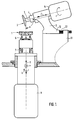
- FIGS. 1 and 2 Of the grinding or milling machine, only the parts 1 and 2 carrying or guiding and driving parts are shown in FIGS. 1 and 2 for simplification.
- the tool 2 is attached via a shaft 3 coaxially to a spindle 4, which is driven by an electric motor 5 so that it can be rotated and its speed can be regulated.
- the workpiece 1 is blocked on a workpiece holder 6, which is concentrically attached to a spindle 7.
- the spindle 7 is driven by a servo motor 8 in a numerically controlled manner.
- Workpiece 1, tool holder 6, spindle 7 and motor 8 as well as all associated parts not specified in more detail are attached to a coordinate device of the machine and can therefore be moved together on mutually perpendicular linear movement axes x and y.
- the common central axis of the parts 1, 6, 7 and 8 coincides with the rotational movement axis b of the workpiece 1.
- the central axis common to the tool 2, the shank 3, the spindle 4 and the motor 5 coincides with the rotational movement axis c of the tool 2 and a tool setting axis z (FIG. 1).
- the linear movement axes x, y and the rotation movement axis b are CNC-controlled, while the rotation movement axis c can only be regulated by speed.
- the axis z is only used for the adjustment of the tool 2 on the rotational movement axis c. Since all CNC axes are combined in the workpiece spindle, simple loading results. The workpiece can be moved into a defined loading and unloading position, so that simple handling devices can also be used for automatic workpiece change.
- the angle ⁇ defined by the machine construction between the two rotational movement axes b and c has the value of 105 °.
- the angle ⁇ is thus determined by the machine construction and cannot be changed.
- the tool spindle 4 with the attached tool 2 and the associated electric motor 5 and all other associated unspecified parts can be adjusted while maintaining the design angle ⁇ for adjusting the tool 2 to the center of the workpiece 1 at right angles to the x-movement axis.
- the aforementioned adjustable parts are rigidly connected via a support arm 9 to a guide carriage 10 which is mounted on a guide bed 11 of the machine so as to be displaceable in the specified direction of adjustment.
- a threaded spindle 12 is effective for adjustment, which on the one hand is rotatable but axially immovable on the guide bed 11 is mounted and on the other hand engages in a corresponding thread of the guide carriage 10.
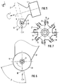
- the grinding tool is disc-shaped with an annular grinding lip 13 located on its circumference. Starting from the end face of the asymmetrically designed grinding lip 13, its radius increases towards the spindle 4, its largest radius ending in a circular shaping cutting edge 14. To carry out the method, this shaping cutting edge must be set on the workpiece such that it is directed approximately radially to the center of the workpiece.
- the rear surface 15 of the grinding lip 13, which ends in the cutting edge 14 and is located on the spindle side, is designed taking into account the constructively defined angle ⁇ such that the rear surface to the tool rotation axis c runs at the angle ⁇ .
- a perpendicular through the lowest point 16 of the cutting edge 14 lies against the rear surface 15 in the manner of a radial surface line.
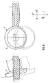
- the lowest point 16 is always in the plane of the two linear axes of movement x and y. This becomes clear when comparing FIGS. 3 and 4.
- the cutting edge 14 is always determined by the largest radius of the grinding lip and is always directed approximately radially to the center of the workpiece even as tool wear progresses. In addition to the wear contour shown in full lines, the new contour of the tool is also shown in dashed lines in FIG. 4. Due to this special tool geometry, the cutting edge always sharpens itself during the grinding process, so that the shape of the surface to be machined is not impaired. The reduction in the cutting edge radius due to wear can easily be taken into account in the computer program of the machine.
- the grinding material of the grinding lip 13 consists of finely divided diamond particles.
- the grinding lip 13 consists either of sintered material, in which the diamond particles are embedded in a finely divided form, or the finely divided diamond particles are applied to the annular grinding lip 13 in a galvanically bonded manner.
- the milling tool 2 ' is disc-shaped with respect to its rotational shape.
- the milling tool 2 ' is provided with a plurality, in the example shown with eight holding arms 17 which are evenly distributed on the circumference and which extend outwards from a central hub part 18.
- the annular cutting edges 20 of the cutting inserts 19 are aligned radially to the axis of rotation c of the milling tool 2 'and define a shaping toric envelope surface, which is indicated by broken lines in FIG. 5.
- the toric envelope surface is oriented approximately radially to the center of the workpiece with respect to its plane formed by its largest radius.
- the deepest point 16 'of the shaping toric envelope is always in the plane of the two linear axes of movement x and y.
- Fig. 6 it is shown that the cutting plates 19 are each fastened to the holding arms 17 by a central screw 21. With the help of the screw 21, the set rotational position of the cutting insert 19 is fixed on the holding arm 17. As indicated in Fig. 6 by the angle dimension ⁇ , only an angle of about 90 ° is used from the circular circumference of the ring cutting edge 20 for the milling process, i.e. only about a quarter of the circumference of the ring cutting edge is used for the milling process. This means that the cutting inserts 19 can be rotated three times into a new position after the first ring cutting sector has worn out.
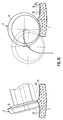
- FIGS. 8 to 11 This process sequence covers all possible machining operations, namely the edge machining operation (FIG. 8), the faceting operation (FIG. 9), the plunge operation (FIG. 10) and the surface processing Final step in the context of the present method with machining along the spiral path (FIG. 11).
- the relative movement of the tool center relative to the workpiece is indicated in dotted lines. In fact, it is not the tool that is moving relative to the workpiece, but the other way round, the workpiece is moving relative to the tool.
- the blocked workpiece 1 is first approximated to the tool 2 by lateral displacement on the x-axis, whereupon the workpiece 1 is displaced on the y-axis relative to the tool 2 which always remains stationary until the workpiece 1 is approximately at the same height as the tool axis is located and the workpiece edge tangent to the circular cutting edge 14.
- material is removed from the workpiece edge.
- processing of the spectacle lens blank is now carried out to the circumferential contour predetermined by the shape of the spectacle frame.
- the tool is attacked at the edge of the workpiece approximately in the manner of a helix.
- the upper workpiece peripheral edge is faceted using the tool.
- This process takes place in a continuous sequence with the others Work steps with constant rotation of workpiece and tool.
- the workpiece 1 is both approximated to the tool 2 on the x-axis and the workpiece is moved downward in a movement overlaid on the y-axis until the desired facet surface 22 is achieved .
- the workpiece 1 is moved relative to the tool 2 during the plunge-in operation by means of coordinated, program-controlled movement on the x and y axes with constant rotation of the workpiece and tool about the associated rotation axes until the tool and workpiece are roughly the same as in FIG 10 take the relative position shown.
- the bulk of the blank material to be removed is removed. This has resulted in an annular trough-shaped surface 23 which is adapted as far as possible to the surface to be produced.
- an outer edge 24 is achieved, which corresponds to the target outer contour of the optically effective inner lens surface. This completes the grooving process.
- the last work step illustrated in FIG. 11 takes place, which serves to remove the remaining amount of the excess blank material until the surface is finally shaped.
- a superimposed movement takes place between the workpiece 1 rotating about its axis b and the otherwise stationary tool 2 rotating about its axis c in the direction of the x and y axes with a spiral course of the machining path 25 shown in FIG. 12 on the machined surface .
- the annular trough-shaped surface resulting from the plunge-in work process disappears, ie the approximately conical central tip of this surface.
- a method for producing a surface from an eyeglass lens blank is described which is suitable for brittle hard materials as well as for plastics.
- a disk-shaped, rotationally symmetrical tool of relatively large diameter is used, with the aid of which the blank material to be removed is removed with a high grinding or milling capacity in at least two work steps, a plunge-cutting step and a shaping step with material removal along a spiral path.
- the last operation results in a machining path running spirally from the outside inwards with a low residual tip height and a relatively large tip spacing.
- the surface created requires only minor fine grinding and polishing post-processing.
- both an edge machining process that adapts to the shape of the spectacle frame and a work step that facets the rim of the spectacle lens can be integrated into the method. Tools for carrying out the grinding or milling process are also proposed.
Applications Claiming Priority (2)
| Application Number | Priority Date | Filing Date | Title |
|---|---|---|---|
| DE19529786A DE19529786C1 (de) | 1995-08-12 | 1995-08-12 | Verfahren und Werkzeug zur Erzeugung einer konkaven Oberfläche an einem Brillenglasrohling |
| DE19529786 | 1995-08-12 |
Publications (4)
| Publication Number | Publication Date |
|---|---|
| EP0758571A1 true EP0758571A1 (fr) | 1997-02-19 |
| EP0758571B1 EP0758571B1 (fr) | 2002-01-16 |
| EP0758571B2 EP0758571B2 (fr) | 2005-09-07 |
| EP0758571B8 EP0758571B8 (fr) | 2005-11-23 |
Family
ID=7769391
Family Applications (1)
| Application Number | Title | Priority Date | Filing Date |
|---|---|---|---|
| EP96112436A Expired - Lifetime EP0758571B8 (fr) | 1995-08-12 | 1996-08-01 | Procédé pour la réalisation d'une surface concave dans une ébauche de verre à lunette |
Country Status (4)
| Country | Link |
|---|---|
| US (2) | US5938381A (fr) |
| EP (1) | EP0758571B8 (fr) |
| DE (2) | DE19529786C1 (fr) |
| ES (1) | ES2171580T5 (fr) |
Cited By (17)
| Publication number | Priority date | Publication date | Assignee | Title |
|---|---|---|---|---|
| FR2805767A1 (fr) * | 2000-03-06 | 2001-09-07 | Essilor Int | Procede de fabrication d'une surface d'une lentille ophtalmique, installation de mise en oeuvre du procede et lentille ophtalmique obtenue selon le procede |
| EP1409198A1 (fr) * | 2000-01-18 | 2004-04-21 | NCRX Optical Solutions, Inc. | Systeme et procede de fabrication de verre ophtalmique |
| EP1679154A1 (fr) * | 2003-10-29 | 2006-07-12 | Seiko Epson Corporation | Systeme et procede d'usinage et procede de formation d'une surface aspherique |
| WO2006097606A1 (fr) * | 2005-03-17 | 2006-09-21 | Essilor International (Compagnie Generale D'optique) | Procede d’usinage d’une face de lentille ophtalmique prismee au centre |
| WO2007017385A3 (fr) * | 2005-08-10 | 2007-06-07 | Schneider Gmbh & Co Kg | Piece de blocage preformee comprenant trois points d'appui |
| EP2011603A1 (fr) | 2007-07-06 | 2009-01-07 | Satisloh AG | Machine destinée au traitement de pièces optiques, en particulier de verres solaires en plastique |
| EP2093018A1 (fr) | 2008-02-25 | 2009-08-26 | Satisloh AG | Pièce de bloc pour maintenir une pièce de travail optique, en particulier un verre de lunette, pour traitement associé, et procédé de fabrication de verres de lunettes selon une prescription |
| US7597033B2 (en) | 2005-05-06 | 2009-10-06 | Satisloh Gmbh | Machine for machining optical workpieces, in particular plastic spectacle lenses |
| EP2138271A1 (fr) | 2008-06-26 | 2009-12-30 | Satisloh AG | Procédé de fabrication de lentilles correctrices sur ordonnance |
| DE102012004547A1 (de) | 2012-03-10 | 2013-09-12 | Satisloh Ag | Vorrichtung zur Feinbearbeitung von optisch wirksamen Flächen an insbesondere Brillengläsern und flexible Fertigungszelle umfassend eine solche Vorrichtung |
| DE102012004543A1 (de) | 2012-03-11 | 2013-09-12 | Satisloh Ag | Maschine zur Bearbeitung von optischen Werkstücken, insbesondere von Kunststoff-Brillengläsern |
| EP2801440A1 (fr) | 2013-05-06 | 2014-11-12 | Satisloh AG | Pièce de blocage à multiples materiaux et procédé utilisant la pièce de blocage |
| EP2826592A1 (fr) | 2013-05-06 | 2015-01-21 | Satisloh AG | Pièce de blocage à parties multiples |
| EP2963458A1 (fr) | 2014-07-05 | 2016-01-06 | Satisloh AG | Ébauche de lentille comportant un revêtement de préhension temporaire pour un procédé de verres de lunettes selon une prescription |
| EP3009230A1 (fr) | 2014-10-15 | 2016-04-20 | Satisloh AG | Unité de blocage pour une pièce de blocage pour un verre de lunettes et procédé de durcissement |
| EP3542956A1 (fr) | 2018-03-23 | 2019-09-25 | Carl Zeiss Vision International GmbH | Procédé de fabrication de lentilles de lunettes selon une ordonnance |
| CN110900319A (zh) * | 2019-12-04 | 2020-03-24 | 南阳利达光电有限公司 | 一种光学零件修模的修正方法 |
Families Citing this family (37)
| Publication number | Priority date | Publication date | Assignee | Title |
|---|---|---|---|---|
| US6170367B1 (en) * | 1998-09-09 | 2001-01-09 | John R. Keller | Single-point flexure toric contact lens forming machine and method |
| AT407353B (de) * | 1998-11-30 | 2001-02-26 | Weingartner Maschbau Gmbh | Verfahren und bearbeitungswerkzeug zum herstellen schraubenförmig profilierter werkstücke |
| JP2001018108A (ja) * | 1999-07-05 | 2001-01-23 | Canon Inc | 回折光学格子素子形状の加工方法及び回折光学格子素子形状を成形する金型の加工方法 |
| US6872120B2 (en) * | 2000-02-16 | 2005-03-29 | Seiko Epson Corporation | Method of producing spectacle lens |
| IL136364A0 (en) * | 2000-05-25 | 2001-06-14 | Avikzar Yehuda | Device for exact machining |
| JP4374161B2 (ja) * | 2001-08-17 | 2009-12-02 | セイコーオプティカルプロダクツ株式会社 | 光学レンズ又はその金型の切削加工方法 |
| DE10143848C2 (de) * | 2001-09-06 | 2003-10-02 | Loh Optikmaschinen Ag | Verfahren und Vorrichtung zur Flächenbearbeitung von Werkstücken aus nicht-sprödharten Materialien in der Optikfertigung sowie Werkzeug dafür |
| DE10218039A1 (de) * | 2002-04-23 | 2003-11-13 | Zeiss Carl | Bearbeitungskopf zur Oberflächenbearbeitung |
| DE10250856A1 (de) | 2002-10-25 | 2004-05-13 | Carl Zeiss | Verfahren und Vorrichtung zum Herstellen von optischen Gläsern |
| US20040116058A1 (en) * | 2002-12-13 | 2004-06-17 | Eastman Kodak Company | Sub-aperture compliant toroidal polishing element |
| US6726413B1 (en) * | 2002-12-16 | 2004-04-27 | Goodrich Corporation | Contour plunge milling |
| EP1608485B1 (fr) | 2003-03-11 | 2011-04-13 | Optotech Optikmaschinen GmbH | Procede et dispositif pour realiser des verres de lunettes et d'autres corps moules ayant des surface optiquement actives |
| DE102004028544B4 (de) * | 2004-01-17 | 2012-01-12 | Asphericon Gmbh | Verfahren zur Bearbeitung und Vermessung von rotationssymmetrischen Werkstücken sowie Schleif- und Polierwerkzeug |
| US7118449B1 (en) * | 2004-09-20 | 2006-10-10 | Carl Zeiss Smt Ag | Method of manufacturing an optical element |
| DE102005021639A1 (de) * | 2005-05-06 | 2006-11-09 | Satisloh Gmbh | Hochleistungs-Fräs- und Drehmaschine sowie Verfahren zur Bearbeitung von Brillengläsern |
| US7390242B2 (en) * | 2005-08-29 | 2008-06-24 | Edge Technologies, Inc. | Diamond tool blade with circular cutting edge |
| DE102005052314A1 (de) * | 2005-11-01 | 2007-05-03 | Satisloh Gmbh | Fast-Tool-Anordnung, insbesondere für Drehmaschinen zur Bearbeitung von optischen Werkstücken |
| KR100974988B1 (ko) * | 2005-12-22 | 2010-08-09 | 호야 가부시키가이샤 | 안경렌즈의 렌즈면 절삭가공장치, 렌즈면 절삭가공방법 및안경렌즈 |
| US7793403B2 (en) * | 2005-12-27 | 2010-09-14 | Konica Minolta Opto, Inc. | Manufacturing method of optical component or molding die therefor |
| ATE407770T1 (de) * | 2006-05-12 | 2008-09-15 | Satisloh Gmbh | Verfahren und vorrichtung für das erzeugen einer optischen oberfläche auf einem werkstück, z.b. ophthalmischen linsen |
| DE102006026524A1 (de) * | 2006-06-06 | 2007-12-13 | Satisloh Ag | Maschine zur Bearbeitung von optischen Werkstücken, insbesondere von Kunststoff-Brillengläsern |
| FR2902683B1 (fr) * | 2006-06-22 | 2008-10-10 | Essilor Int | Procede et machine d'usinage pour objet optique. |
| JP5401757B2 (ja) * | 2006-11-30 | 2014-01-29 | 株式会社ジェイテクト | 加工装置 |
| US8460060B2 (en) * | 2009-01-30 | 2013-06-11 | Smr Patents S.A.R.L. | Method for creating a complex surface on a substrate of glass |
| CN102120305A (zh) * | 2010-12-23 | 2011-07-13 | 山西力天世纪刀具有限公司 | 一种用于加工金刚石球形面的磨床 |
| DE102011014230A1 (de) * | 2011-03-17 | 2012-09-20 | Satisloh Ag | Vorrichtung zur Feinbearbeitung von optisch wirksamen Flächen an insbesondere Brillengläsern |
| FR2982785B1 (fr) * | 2011-11-22 | 2013-12-20 | Essilor Int | Procede d'obtention d'une lentille ophtalmique |
| SG11201510027RA (en) * | 2013-06-07 | 2016-01-28 | 3M Innovative Properties Co | Method of forming a recess in a substrate, abrasive wheel, and cover |
| DE102014003598B4 (de) * | 2014-03-17 | 2020-02-27 | Satisloh Ag | Vorrichtung zum Schleifen, Feinschleifen und/oder Polieren von Werkstücken in optischer Qualität, insbesondere von sphärischen Linsenflächen in der Feinoptik |
| EP3200954B1 (fr) * | 2014-10-03 | 2020-12-09 | Zeeko Innovations Limited | Outil et procédé de mise en forme et de finition d'une pièce |
| USD785339S1 (en) * | 2014-10-23 | 2017-05-02 | Griot's Garage, Inc. | Hand applicator buffing pad |
| WO2017002326A1 (fr) * | 2015-06-29 | 2017-01-05 | 兼房株式会社 | Procédé d'embrèvement utilisant une fraise en bout, et fraise en bout |
| CN109014352A (zh) * | 2018-05-25 | 2018-12-18 | 常州星宇车灯股份有限公司 | 一种透镜微条纹的加工方法和带微条纹的透镜 |
| JP7171131B2 (ja) * | 2018-08-29 | 2022-11-15 | 株式会社ディスコ | 被加工物の研削方法 |
| DE102021004831A1 (de) | 2021-09-24 | 2023-03-30 | Satisloh Ag | Verfahren zur spanenden bearbeitung von optischen werkstücken, insbesondere brillenlinsen aus kunststoff |
| DE102021005202A1 (de) | 2021-10-19 | 2023-04-20 | Satisloh Ag | Aufnahme für die Bearbeitung von optischen Werkstücken, insbesondere Brillenlinsen |
| CN114633030B (zh) * | 2022-02-24 | 2024-03-26 | 江门金鸿桦烨电子科技有限公司 | 一种镜片加工方法 |
Citations (6)
| Publication number | Priority date | Publication date | Assignee | Title |
|---|---|---|---|---|
| US3212405A (en) * | 1963-07-24 | 1965-10-19 | Helen Sue Smith | Method for cutting internal spherical surfaces |
| US3877177A (en) * | 1972-07-17 | 1975-04-15 | Canon Kk | Device for machining spherical surfaces |
| DE3125915A1 (de) * | 1981-07-01 | 1983-01-20 | Licentia Patent-Verwaltungs-Gmbh, 6000 Frankfurt | Verfahren zum herstellen einer vorratskathode und vorrichtung zur durchfuehrung des verfahrens |
| EP0453627A2 (fr) * | 1990-04-24 | 1991-10-30 | NATIONAL OPTRONICS, Inc. | Méthode et appareil pour la réalisation de lentilles en matière plastique |
| WO1992000832A1 (fr) * | 1990-07-12 | 1992-01-23 | Loh Optical Machinery, Inc. | Surfaceuse commandee par ordinateur pour lentilles |
| DE4210381A1 (de) * | 1992-03-30 | 1993-10-14 | Seiko Epson Corp | Verfahren und Vorrichtung zum Bilden einer nichtachsensymmetrischen asphärischen Fläche |
Family Cites Families (28)
| Publication number | Priority date | Publication date | Assignee | Title |
|---|---|---|---|---|
| US2231900A (en) † | 1938-08-30 | 1941-02-18 | Arthur J Geoffrion | Abrading device |
| US3374586A (en) * | 1965-05-03 | 1968-03-26 | Textron Inc | Lens-grinding wheel |
| US3704554A (en) * | 1971-04-26 | 1972-12-05 | Bausch & Lomb | Lens processing machine with movable workpiece spindle |
| US3866358A (en) * | 1973-08-02 | 1975-02-18 | Itek Corp | Method and apparatus for generating toroidal surfaces |
| US3902277A (en) * | 1974-04-01 | 1975-09-02 | Itek Corp | Method and apparatus for generating toric surfaces by the use of a peripheral surfacing tool |
| US4271633A (en) * | 1977-12-23 | 1981-06-09 | U.S. Product Development Company | Molding for vehicle door edges |
| US4271636A (en) * | 1979-09-21 | 1981-06-09 | American Optical Corporation | Lens generating apparatus |
| US4177699A (en) † | 1978-06-21 | 1979-12-11 | Dovnar Stanislav A | Method of machining end faces |
| DE3034788A1 (de) * | 1979-09-20 | 1981-04-02 | Ewag AG, Maschinen- und Werkzeugfabrik, Solothurn | Universal-schleifmaschine |
| US4680998A (en) * | 1984-08-28 | 1987-07-21 | Bausch & Lomb Incorporated | Toric lenses, method and apparatus for making same |
| US4574527A (en) * | 1984-10-05 | 1986-03-11 | Craxton Robert S | Toric lens generating |
| US4862646A (en) † | 1986-01-28 | 1989-09-05 | Laser Magnetic Storage International Company | Apparatus and method for production of single element toric lenses of very small proportions |
| US4760672A (en) * | 1986-12-10 | 1988-08-02 | Corning Glass Works | Simultaneously grinding and polishing preforms for optical lenses |
| US4989316A (en) † | 1987-03-09 | 1991-02-05 | Gerber Scientific Products, Inc. | Method and apparatus for making prescription eyeglass lenses |
| US4856234A (en) * | 1988-02-26 | 1989-08-15 | Research Machine Center, Inc. | Optical lens manufacturing apparatus and method |
| US4866884A (en) * | 1988-09-09 | 1989-09-19 | Coburn Optical Industries, Inc. | Lens grinding methods and apparatus |
| US5231587A (en) * | 1990-07-12 | 1993-07-27 | Loh Optical Machinery, Inc. | Computer controlled lens surfacer |
| JP3026824B2 (ja) * | 1990-07-31 | 2000-03-27 | 株式会社メニコン | 非球面レンズの製造装置 |
| DE59209685D1 (de) * | 1991-07-01 | 1999-06-02 | Wernicke & Co Gmbh | Verfahren zur herstellung eines gerandeten brillenglases |
| DE4221377A1 (de) † | 1991-07-01 | 1993-01-07 | Wernicke & Co Gmbh | Verfahren zur herstellung eines gerandeten brillenglases |
| FR2681546B1 (fr) * | 1991-09-20 | 1995-12-08 | Essilor Int | Procede et machine d'usinage a commande numerique multi-axe. |
| US5320006A (en) * | 1991-09-27 | 1994-06-14 | Coburn Optical Industries, Inc. | Methods and apparatus for producing ophthalmic lenses |
| US5485771A (en) * | 1991-09-27 | 1996-01-23 | Coburn Optical Industries, Inc. | Apparatus for generating ophthalmic products from blanks and a method of operating same |
| DE9303054U1 (de) * | 1993-03-03 | 1994-04-07 | Pokolm Franz Josef | Kopierfräser |
| BE1008917A3 (fr) * | 1994-11-16 | 1996-10-01 | Diamant Boart Sa | Outil abrasif, de coupe ou analogue et procede de fabrication de cet outil. |
| FR2741560B1 (fr) * | 1995-11-23 | 1998-02-06 | Briot Int | Meule perfectionnee pour verres ophtalmiques, et machine de meulage correspondante |
| US5720649A (en) * | 1995-12-22 | 1998-02-24 | Gerber Optical, Inc. | Optical lens or lap blank surfacing machine, related method and cutting tool for use therewith |
| US5888129A (en) * | 1996-05-15 | 1999-03-30 | Neff; Charles E. | Grinding wheel |
-
1995
- 1995-08-12 DE DE19529786A patent/DE19529786C1/de not_active Expired - Lifetime
-
1996
- 1996-08-01 ES ES96112436T patent/ES2171580T5/es not_active Expired - Lifetime
- 1996-08-01 EP EP96112436A patent/EP0758571B8/fr not_active Expired - Lifetime
- 1996-08-01 DE DE59608585T patent/DE59608585D1/de not_active Expired - Lifetime
- 1996-08-12 US US08/695,789 patent/US5938381A/en not_active Expired - Lifetime
-
1999
- 1999-06-10 US US09/329,505 patent/US6227952B1/en not_active Expired - Lifetime
Patent Citations (6)
| Publication number | Priority date | Publication date | Assignee | Title |
|---|---|---|---|---|
| US3212405A (en) * | 1963-07-24 | 1965-10-19 | Helen Sue Smith | Method for cutting internal spherical surfaces |
| US3877177A (en) * | 1972-07-17 | 1975-04-15 | Canon Kk | Device for machining spherical surfaces |
| DE3125915A1 (de) * | 1981-07-01 | 1983-01-20 | Licentia Patent-Verwaltungs-Gmbh, 6000 Frankfurt | Verfahren zum herstellen einer vorratskathode und vorrichtung zur durchfuehrung des verfahrens |
| EP0453627A2 (fr) * | 1990-04-24 | 1991-10-30 | NATIONAL OPTRONICS, Inc. | Méthode et appareil pour la réalisation de lentilles en matière plastique |
| WO1992000832A1 (fr) * | 1990-07-12 | 1992-01-23 | Loh Optical Machinery, Inc. | Surfaceuse commandee par ordinateur pour lentilles |
| DE4210381A1 (de) * | 1992-03-30 | 1993-10-14 | Seiko Epson Corp | Verfahren und Vorrichtung zum Bilden einer nichtachsensymmetrischen asphärischen Fläche |
Non-Patent Citations (1)
| Title |
|---|
| FRIEDMAR MACKSCHEIDT: "Bedeutung der Sonderwerzeuge - Anwendungsbeispiele für Serien mit mittleren Stückzahlen.", MASCHINENMARKT, vol. 82, no. 86, 1976, WÜRZBURG, DE, pages 1577 - 1580, XP002017834 * |
Cited By (38)
| Publication number | Priority date | Publication date | Assignee | Title |
|---|---|---|---|---|
| EP1409198A4 (fr) * | 2000-01-18 | 2007-09-12 | Ncrx Optical Solutions Inc | Systeme et procede de fabrication de verre ophtalmique |
| EP1409198A1 (fr) * | 2000-01-18 | 2004-04-21 | NCRX Optical Solutions, Inc. | Systeme et procede de fabrication de verre ophtalmique |
| WO2001066308A1 (fr) * | 2000-03-06 | 2001-09-13 | Essilor International (Compagnie Generale D'optique) | Procede de fabrication d'une surface d'une lentille ophtalmique, installation de mise en oeuvre du procede et lentille ophtalmique obtenue selon le procede |
| US6558586B1 (en) | 2000-03-06 | 2003-05-06 | Essilor International (Compagnie Generale D'optique) | Process for fabricating a surface of an ophthalmic lens, installation for implementing the process and ophthalmic lens obtained by the process |
| FR2805767A1 (fr) * | 2000-03-06 | 2001-09-07 | Essilor Int | Procede de fabrication d'une surface d'une lentille ophtalmique, installation de mise en oeuvre du procede et lentille ophtalmique obtenue selon le procede |
| EP1679154A1 (fr) * | 2003-10-29 | 2006-07-12 | Seiko Epson Corporation | Systeme et procede d'usinage et procede de formation d'une surface aspherique |
| EP1679154A4 (fr) * | 2003-10-29 | 2009-08-19 | Seiko Epson Corp | Systeme et procede d'usinage et procede de formation d'une surface aspherique |
| US8215210B2 (en) | 2005-03-17 | 2012-07-10 | Essilor International (Compagnie Generale D'optique) | Method of machining a face of an ophthalmic lens that is prism-ballasted at the centre |
| CN101142054B (zh) * | 2005-03-17 | 2010-08-11 | 埃西勒国际通用光学公司 | 加工中心为角柱形的眼镜片表面的方法 |
| AU2006224447B2 (en) * | 2005-03-17 | 2011-01-20 | Essilor International | Method of machining a face of an ophthalmic lens that is prism-ballasted at the centre |
| WO2006097606A1 (fr) * | 2005-03-17 | 2006-09-21 | Essilor International (Compagnie Generale D'optique) | Procede d’usinage d’une face de lentille ophtalmique prismee au centre |
| FR2883215A1 (fr) * | 2005-03-17 | 2006-09-22 | Essilor Int | Procede d'usinage d'une face de lentille optalmique prismee au centre |
| US7597033B2 (en) | 2005-05-06 | 2009-10-06 | Satisloh Gmbh | Machine for machining optical workpieces, in particular plastic spectacle lenses |
| DE202006021076U1 (de) | 2005-05-06 | 2012-04-16 | Satisloh Gmbh | Maschine zur Bearbeitung von optischen Werkstücken, insbesondere von Kunststoff-Brillengläsern |
| DE202006020913U1 (de) | 2005-05-06 | 2010-10-28 | Satisloh Gmbh | Maschine zur Bearbeitung von optischen Werkstücken, namentlich von Kunststoff-Brillengläsern |
| EP2338640A1 (fr) | 2005-05-06 | 2011-06-29 | Satisloh GmbH | Machine de meulage de pièces optiques, en particuliere de verres à lunettes en plastique |
| WO2007017385A3 (fr) * | 2005-08-10 | 2007-06-07 | Schneider Gmbh & Co Kg | Piece de blocage preformee comprenant trois points d'appui |
| US9381604B2 (en) | 2005-08-10 | 2016-07-05 | Schneider Gmbh & Co. Kg | Preformed block piece with three points of support |
| CN101337281B (zh) * | 2007-07-06 | 2013-04-24 | 萨特隆股份公司 | 用于加工处理光学工件、尤其是塑料镜片的机器 |
| DE102007031703A1 (de) | 2007-07-06 | 2009-01-08 | Satisloh Gmbh | Maschine zur Bearbeitung von optischen Werkstücken, insbesondere von Kunststoff-Brillengläsern |
| EP2011603A1 (fr) | 2007-07-06 | 2009-01-07 | Satisloh AG | Machine destinée au traitement de pièces optiques, en particulier de verres solaires en plastique |
| EP2266753A1 (fr) | 2008-02-25 | 2010-12-29 | Satisloh AG | Pièce de bloc pour maintenir une pièce de travail optique, en particulier un verre de lunette, pour traitement associé, et procédé de fabrication de verres de lunettes selon une prescription |
| WO2009106296A1 (fr) | 2008-02-25 | 2009-09-03 | Satisloh Ag | Pièce de blocage destinée à maintenir une pièce optique à usiner, notamment un verre de lunettes, à des fins de traitement, et procédé destiné à fabriquer un verre de lunettes conformément à une prescription |
| EP2093018A1 (fr) | 2008-02-25 | 2009-08-26 | Satisloh AG | Pièce de bloc pour maintenir une pièce de travail optique, en particulier un verre de lunette, pour traitement associé, et procédé de fabrication de verres de lunettes selon une prescription |
| EP2138271A1 (fr) | 2008-06-26 | 2009-12-30 | Satisloh AG | Procédé de fabrication de lentilles correctrices sur ordonnance |
| DE102012004547A1 (de) | 2012-03-10 | 2013-09-12 | Satisloh Ag | Vorrichtung zur Feinbearbeitung von optisch wirksamen Flächen an insbesondere Brillengläsern und flexible Fertigungszelle umfassend eine solche Vorrichtung |
| WO2013135331A1 (fr) | 2012-03-10 | 2013-09-19 | Satisloh Ag | Dispositif pour l'usinage fin de surfaces optiquement actives, en particulier sur des verres de lunette, et cellule d'usinage souple comprenant un tel dispositif |
| DE102012004543A1 (de) | 2012-03-11 | 2013-09-12 | Satisloh Ag | Maschine zur Bearbeitung von optischen Werkstücken, insbesondere von Kunststoff-Brillengläsern |
| WO2013135330A1 (fr) | 2012-03-11 | 2013-09-19 | Satisloh Ag | Machine d'usinage de pièces optiques, en particulier de verres de lunettes en matière plastique |
| EP2826592A1 (fr) | 2013-05-06 | 2015-01-21 | Satisloh AG | Pièce de blocage à parties multiples |
| DE202014009911U1 (de) | 2013-05-06 | 2015-01-16 | Satisloh Ag | Multimaterial Blockstück |
| EP2801440A1 (fr) | 2013-05-06 | 2014-11-12 | Satisloh AG | Pièce de blocage à multiples materiaux et procédé utilisant la pièce de blocage |
| EP2963458A1 (fr) | 2014-07-05 | 2016-01-06 | Satisloh AG | Ébauche de lentille comportant un revêtement de préhension temporaire pour un procédé de verres de lunettes selon une prescription |
| EP3009230A1 (fr) | 2014-10-15 | 2016-04-20 | Satisloh AG | Unité de blocage pour une pièce de blocage pour un verre de lunettes et procédé de durcissement |
| US10259096B2 (en) | 2014-10-15 | 2019-04-16 | Satisloh Ag | Blocking unit for a block piece for a spectacle lens and process of curing |
| EP3542956A1 (fr) | 2018-03-23 | 2019-09-25 | Carl Zeiss Vision International GmbH | Procédé de fabrication de lentilles de lunettes selon une ordonnance |
| WO2019179660A1 (fr) | 2018-03-23 | 2019-09-26 | Carl Zeiss Vision International Gmbh | Procédé de fabrication de verres à lunettes suivant une ordonnance |
| CN110900319A (zh) * | 2019-12-04 | 2020-03-24 | 南阳利达光电有限公司 | 一种光学零件修模的修正方法 |
Also Published As
| Publication number | Publication date |
|---|---|
| US6227952B1 (en) | 2001-05-08 |
| EP0758571B2 (fr) | 2005-09-07 |
| DE19529786C1 (de) | 1997-03-06 |
| EP0758571B8 (fr) | 2005-11-23 |
| ES2171580T5 (es) | 2006-03-16 |
| ES2171580T3 (es) | 2002-09-16 |
| DE59608585D1 (de) | 2002-02-21 |
| MX9603307A (es) | 1997-07-31 |
| EP0758571B1 (fr) | 2002-01-16 |
| US5938381A (en) | 1999-08-17 |
Similar Documents
| Publication | Publication Date | Title |
|---|---|---|
| EP0758571B1 (fr) | Procédé et outil pour la réalisation d'une surface concave dans une ébauche de verre à lunette | |
| EP2823924B1 (fr) | Machine à dresser double | |
| DE102006061759B4 (de) | Verzahnungsschleifmaschine und Verfahren zum Schleifen eines Werkstücks | |
| EP1291106B1 (fr) | Méthode et appareil pour le machinage de surface de pièces en matériaux non fragiles dans la fabrication d'optiques, et outil associé | |
| EP1719585B1 (fr) | Machine destinée au traitement de pièces optiques, nominalement de verres de lunettes en plastique | |
| EP1526946B1 (fr) | Procede et systeme de polissage d'un piece de machine a symetrie de revolution comprenant un alesage longitudinal | |
| EP2326449B1 (fr) | Outil de dressage et procede pour le dressage d'un outil de meulage | |
| DE10308292B4 (de) | Verfahren zum Rundschleifen bei der Herstellung von Werkzeugen aus Hartmetall und Rundschleifmaschine zum Schleifen von zylindrischen Ausgangskörpern bei der Herstellung von Werkzeugen aus Hartmetall | |
| EP2046528B1 (fr) | Procédé pour meuler une plaque de coupe amovible et plaque de coupe pour mettre en uvre le procédé de meulage | |
| EP1422005B1 (fr) | Procédé et dispositif pour l'usinage du bord de lentilles ophtalmiques en plastique | |
| WO2019120831A1 (fr) | Procédé d'usinage de dentures, machine de denture et programme de commande associé | |
| EP1144138B1 (fr) | Procede pour meuler au moins une face d'une lame utilisee dans la technique d'enlevement de copeaux, mise en oeuvre de ce procede et meule pour la mise en oeuvre dudit procede | |
| DE4107462C2 (de) | Werkzeugmaschine zur spanabhebenden Bearbeitung von Werkstücken | |
| WO1999011429A1 (fr) | Machine d'usinage de bord de verre de lunettes | |
| CH685544A5 (de) | Verfahren zum Umfangs- und Fasenschleifen von Schneidplatten und Vorrichtung zur Durchführung des Verfahrens. | |
| EP1595628B1 (fr) | Outil pour l'usinage avec enlèvement de copeaux | |
| DE10113301B4 (de) | Verfahren und Vorrichtung zum Hinterschleifen der Schneidzähne von zylindrisch oder kegelig geformten Abwalzfräsern sowie Abwalzfräser | |
| DE3520521A1 (de) | Maschine zum spanenden einarbeiten der spanraumnuten von laenglichen, am umfang schneidenden werkzeugen mit halbkugelfoermigem ende | |
| EP0841116A2 (fr) | Méthode de travail de surfaces de pièces symétriques en rotation et outil employé | |
| EP0119236B1 (fr) | Tour automatique a broches multiples | |
| DE19616525A1 (de) | Werkzeug zur materialabtragenden Bearbeitung optischer Werkstoffe | |
| DE188491C (fr) | ||
| DD232863A5 (de) | Verfahren und vorrichtung vom hochgeschwindigkeits-profilschleifen von rotationssymmetrischen werkstuecken | |
| DE10103121A1 (de) | Verfahren zum Schleifen von wenigstens einer Fläche an einem in der Zerspantechnik eingesetzten Schneidmesser | |
| EP1870204A1 (fr) | Procédé et dispositif destinés à al fabrication et/ou au traitement automatique de rainures radiales dans des pièces à usiner en matériaux très résistants |
Legal Events
| Date | Code | Title | Description |
|---|---|---|---|
| PUAI | Public reference made under article 153(3) epc to a published international application that has entered the european phase |
Free format text: ORIGINAL CODE: 0009012 |
|
| AK | Designated contracting states |
Kind code of ref document: A1 Designated state(s): DE ES FR GB IT NL |
|
| 17P | Request for examination filed |
Effective date: 19970210 |
|
| 17Q | First examination report despatched |
Effective date: 20001004 |
|
| GRAG | Despatch of communication of intention to grant |
Free format text: ORIGINAL CODE: EPIDOS AGRA |
|
| GRAG | Despatch of communication of intention to grant |
Free format text: ORIGINAL CODE: EPIDOS AGRA |
|
| GRAG | Despatch of communication of intention to grant |
Free format text: ORIGINAL CODE: EPIDOS AGRA |
|
| GRAH | Despatch of communication of intention to grant a patent |
Free format text: ORIGINAL CODE: EPIDOS IGRA |
|
| GRAH | Despatch of communication of intention to grant a patent |
Free format text: ORIGINAL CODE: EPIDOS IGRA |
|
| GRAA | (expected) grant |
Free format text: ORIGINAL CODE: 0009210 |
|
| REG | Reference to a national code |
Ref country code: GB Ref legal event code: IF02 |
|
| AK | Designated contracting states |
Kind code of ref document: B1 Designated state(s): DE ES FR GB IT NL |
|
| REF | Corresponds to: |
Ref document number: 59608585 Country of ref document: DE Date of ref document: 20020221 |
|
| GBT | Gb: translation of ep patent filed (gb section 77(6)(a)/1977) |
Effective date: 20020406 |
|
| ET | Fr: translation filed | ||
| REG | Reference to a national code |
Ref country code: ES Ref legal event code: FG2A Ref document number: 2171580 Country of ref document: ES Kind code of ref document: T3 |
|
| PLBQ | Unpublished change to opponent data |
Free format text: ORIGINAL CODE: EPIDOS OPPO |
|
| PLBI | Opposition filed |
Free format text: ORIGINAL CODE: 0009260 |
|
| PLBF | Reply of patent proprietor to notice(s) of opposition |
Free format text: ORIGINAL CODE: EPIDOS OBSO |
|
| 26 | Opposition filed |
Opponent name: GERBER COBUM OPTICAL INC. Effective date: 20021016 Opponent name: OPTISCHE WERKE G. RODENSTOCK Effective date: 20021016 |
|
| NLR1 | Nl: opposition has been filed with the epo |
Opponent name: GERBER COBUM OPTICAL INC. Opponent name: OPTISCHE WERKE G. RODENSTOCK |
|
| PLBF | Reply of patent proprietor to notice(s) of opposition |
Free format text: ORIGINAL CODE: EPIDOS OBSO |
|
| PLBF | Reply of patent proprietor to notice(s) of opposition |
Free format text: ORIGINAL CODE: EPIDOS OBSO |
|
| PLBB | Reply of patent proprietor to notice(s) of opposition received |
Free format text: ORIGINAL CODE: EPIDOSNOBS3 |
|
| PLAB | Opposition data, opponent's data or that of the opponent's representative modified |
Free format text: ORIGINAL CODE: 0009299OPPO |
|
| PLBQ | Unpublished change to opponent data |
Free format text: ORIGINAL CODE: EPIDOS OPPO |
|
| R26 | Opposition filed (corrected) |
Opponent name: GERBER COBUM OPTICAL INC.PATENTANWAELTE Effective date: 20021016 Opponent name: OPTISCHE WERKE G. RODENSTOCK Effective date: 20021016 |
|
| NLR1 | Nl: opposition has been filed with the epo |
Opponent name: GERBER COBUM OPTICAL INC. Opponent name: OPTISCHE WERKE G. RODENSTOCK |
|
| PLAB | Opposition data, opponent's data or that of the opponent's representative modified |
Free format text: ORIGINAL CODE: 0009299OPPO |
|
| R26 | Opposition filed (corrected) |
Opponent name: GERBER COBUM OPTICAL INC.PATENTANWAELTE Effective date: 20021016 Opponent name: RODENSTOCK GMBH Effective date: 20021016 |
|
| NLR1 | Nl: opposition has been filed with the epo |
Opponent name: GERBER COBUM OPTICAL INC. Opponent name: RODENSTOCK GMBH |
|
| PLBP | Opposition withdrawn |
Free format text: ORIGINAL CODE: 0009264 |
|
| RTI2 | Title (correction) |
Free format text: PROCESS FOR MANUFACTURING A CONCAVE OUTER SURFACE ON A SPECTACLE LENS BLANK |
|
| PUAH | Patent maintained in amended form |
Free format text: ORIGINAL CODE: 0009272 |
|
| STAA | Information on the status of an ep patent application or granted ep patent |
Free format text: STATUS: PATENT MAINTAINED AS AMENDED |
|
| 27A | Patent maintained in amended form |
Effective date: 20050907 |
|
| AK | Designated contracting states |
Kind code of ref document: B2 Designated state(s): DE ES FR GB IT NL |
|
| NLR2 | Nl: decision of opposition |
Effective date: 20050907 |
|
| NLR3 | Nl: receipt of modified translations in the netherlands language after an opposition procedure | ||
| GBTA | Gb: translation of amended ep patent filed (gb section 77(6)(b)/1977) | ||
| RAP2 | Party data changed (patent owner data changed or rights of a patent transferred) |
Owner name: SATISLOH GMBH |
|
| REG | Reference to a national code |
Ref country code: ES Ref legal event code: DC2A Date of ref document: 20051202 Kind code of ref document: T5 |
|
| NLXE | Nl: other communications concerning ep-patents (part 3 heading xe) |
Free format text: PAT. BUL. 02/2006: CORR.: SATISLOH GMBH. |
|
| ET3 | Fr: translation filed ** decision concerning opposition | ||
| PLAB | Opposition data, opponent's data or that of the opponent's representative modified |
Free format text: ORIGINAL CODE: 0009299OPPO |
|
| PGFP | Annual fee paid to national office [announced via postgrant information from national office to epo] |
Ref country code: FR Payment date: 20130604 Year of fee payment: 18 |
|
| PGFP | Annual fee paid to national office [announced via postgrant information from national office to epo] |
Ref country code: NL Payment date: 20130815 Year of fee payment: 18 Ref country code: ES Payment date: 20130806 Year of fee payment: 18 |
|
| PGFP | Annual fee paid to national office [announced via postgrant information from national office to epo] |
Ref country code: GB Payment date: 20130930 Year of fee payment: 18 |
|
| PGFP | Annual fee paid to national office [announced via postgrant information from national office to epo] |
Ref country code: IT Payment date: 20130827 Year of fee payment: 18 |
|
| REG | Reference to a national code |
Ref country code: NL Ref legal event code: V1 Effective date: 20150301 |
|
| GBPC | Gb: european patent ceased through non-payment of renewal fee |
Effective date: 20140801 |
|
| PG25 | Lapsed in a contracting state [announced via postgrant information from national office to epo] |
Ref country code: IT Free format text: LAPSE BECAUSE OF NON-PAYMENT OF DUE FEES Effective date: 20140801 Ref country code: NL Free format text: LAPSE BECAUSE OF NON-PAYMENT OF DUE FEES Effective date: 20150301 |
|
| REG | Reference to a national code |
Ref country code: FR Ref legal event code: ST Effective date: 20150430 |
|
| PG25 | Lapsed in a contracting state [announced via postgrant information from national office to epo] |
Ref country code: GB Free format text: LAPSE BECAUSE OF NON-PAYMENT OF DUE FEES Effective date: 20140801 |
|
| PG25 | Lapsed in a contracting state [announced via postgrant information from national office to epo] |
Ref country code: FR Free format text: LAPSE BECAUSE OF NON-PAYMENT OF DUE FEES Effective date: 20140901 |
|
| REG | Reference to a national code |
Ref country code: ES Ref legal event code: FD2A Effective date: 20150925 |
|
| PG25 | Lapsed in a contracting state [announced via postgrant information from national office to epo] |
Ref country code: ES Free format text: LAPSE BECAUSE OF NON-PAYMENT OF DUE FEES Effective date: 20140802 |
|
| PGFP | Annual fee paid to national office [announced via postgrant information from national office to epo] |
Ref country code: DE Payment date: 20150827 Year of fee payment: 20 |
|
| REG | Reference to a national code |
Ref country code: DE Ref legal event code: R071 Ref document number: 59608585 Country of ref document: DE |