EP0756933A2 - Verfahren und Apparat zum Herstellen eines Farbfilters, diesen Farbfilter verwendende Anzeigevorrichtung und elektronische Apparatur mit dieser Anzeigevorrichtung - Google Patents
Verfahren und Apparat zum Herstellen eines Farbfilters, diesen Farbfilter verwendende Anzeigevorrichtung und elektronische Apparatur mit dieser Anzeigevorrichtung Download PDFInfo
- Publication number
- EP0756933A2 EP0756933A2 EP96305472A EP96305472A EP0756933A2 EP 0756933 A2 EP0756933 A2 EP 0756933A2 EP 96305472 A EP96305472 A EP 96305472A EP 96305472 A EP96305472 A EP 96305472A EP 0756933 A2 EP0756933 A2 EP 0756933A2
- Authority
- EP
- European Patent Office
- Prior art keywords
- ink
- color
- jet head
- substrate
- color filter
- Prior art date
- Legal status (The legal status is an assumption and is not a legal conclusion. Google has not performed a legal analysis and makes no representation as to the accuracy of the status listed.)
- Granted
Links
Images


Classifications
-
- B—PERFORMING OPERATIONS; TRANSPORTING
- B41—PRINTING; LINING MACHINES; TYPEWRITERS; STAMPS
- B41J—TYPEWRITERS; SELECTIVE PRINTING MECHANISMS, i.e. MECHANISMS PRINTING OTHERWISE THAN FROM A FORME; CORRECTION OF TYPOGRAPHICAL ERRORS
- B41J2/00—Typewriters or selective printing mechanisms characterised by the printing or marking process for which they are designed
- B41J2/005—Typewriters or selective printing mechanisms characterised by the printing or marking process for which they are designed characterised by bringing liquid or particles selectively into contact with a printing material
- B41J2/01—Ink jet
-
- G—PHYSICS
- G02—OPTICS
- G02B—OPTICAL ELEMENTS, SYSTEMS OR APPARATUS
- G02B5/00—Optical elements other than lenses
- G02B5/20—Filters
- G02B5/201—Filters in the form of arrays
-
- B—PERFORMING OPERATIONS; TRANSPORTING
- B41—PRINTING; LINING MACHINES; TYPEWRITERS; STAMPS
- B41J—TYPEWRITERS; SELECTIVE PRINTING MECHANISMS, i.e. MECHANISMS PRINTING OTHERWISE THAN FROM A FORME; CORRECTION OF TYPOGRAPHICAL ERRORS
- B41J2/00—Typewriters or selective printing mechanisms characterised by the printing or marking process for which they are designed
- B41J2/005—Typewriters or selective printing mechanisms characterised by the printing or marking process for which they are designed characterised by bringing liquid or particles selectively into contact with a printing material
- B41J2/01—Ink jet
- B41J2/21—Ink jet for multi-colour printing
- B41J2/2132—Print quality control characterised by dot disposition, e.g. for reducing white stripes or banding
-
- B—PERFORMING OPERATIONS; TRANSPORTING
- B41—PRINTING; LINING MACHINES; TYPEWRITERS; STAMPS
- B41J—TYPEWRITERS; SELECTIVE PRINTING MECHANISMS, i.e. MECHANISMS PRINTING OTHERWISE THAN FROM A FORME; CORRECTION OF TYPOGRAPHICAL ERRORS
- B41J2202/00—Embodiments of or processes related to ink-jet or thermal heads
- B41J2202/01—Embodiments of or processes related to ink-jet heads
- B41J2202/09—Ink jet technology used for manufacturing optical filters
Definitions
- the present invention relates to a method and apparatus for manufacturing a color filter for a color liquid crystal display used in, e.g., a color television, a personal computer, or the like, a display device using the color filter, and an electronic equipment comprising the color display device.
- Each color element (pixel) of such color filter manufactured by using the ink-jet method has a width of one dot ejected from one nozzle of an ink-jet head, and a length of a plurality of dots in its longitudinal direction.
- the color filter is constituted by arranging a plurality of color elements on a glass substrate.
- the ink-jet head is scanned along the widthwise direction of the color filter, and each color element is formed by ink ejected from one nozzle. For this reason, if the amounts of ink ejected from nozzles vary, the variations of the amount of ink appear as variations in densities of the color elements.
- the present invention has been made in consideration of the prior art, and has as its object to provide a method and apparatus for manufacturing a color filter, which can suppress variations in colors and densities of color elements by forming one color element by ink ejected from different nozzles.
- Fig. 1 is a perspective view showing the outer appearance of a color filter manufacturing apparatus 90 according to an embodiment of the present invention.
- reference numeral 51 denotes a base of the apparatus; 52, an XY ⁇ stage arranged on the base 51; 53, a glass substrate for a color filter, which is set on the XY ⁇ stage 52; and 54, color filter portions formed on the color filter substrate 53.
- Reference numeral 55 denotes R (red), G (green), and B (blue) ink-jet heads for performing coloring on the color filter portions 54.
- Reference numeral 56 denotes a television camera having a built-in line sensor for reading a portion where color elements are formed by the ink-jet heads 55, and detecting non-ejection nozzles of the heads 55.
- Reference numeral 57 denotes an image processing device for processing image data picked up by the television camera 56, and inspecting the presence/absence of non-ejection nozzles of the ink-jet heads 55; 58, a controller for controlling the operation of the overall color filter manufacturing apparatus 90; 59, a teaching pendant (personal computer) having a display 62 and input units (keyboard) 60 of the controller 58; and the keyboard 60 serves as an operation unit of the personal computer 59.
- a teaching pendant personal computer having a display 62 and input units (keyboard) 60 of the controller 58; and the keyboard 60 serves as an operation unit of the personal computer 59.
- Fig. 2 is a block diagram showing the arrangement of the controller 58 for controlling the color filter manufacturing apparatus 90 of this embodiment.
- the personal computer 59 serves as input/output means of the controller 58, and a display unit 62 displays information such as the progress of the manufacture of the color filter, the presence/absence of abnormalities of the heads 55, and the like.
- Reference numeral 60 denotes an operation unit (keyboard) for instructing the operations and the like of the color filter manufacturing apparatus 90.
- the controller 58 controls the operation of the overall color filter manufacturing apparatus 90.
- An interface 65 controls data exchange between the personal computer 59 and the controller 58.
- Reference numeral 66 denotes a CPU for controlling the color filter manufacturing apparatus 90 of this embodiment; 67, a ROM for storing a control program for controlling the operation of the CPU 66; 68, a RAM which is used as a work area under control of the CPU 66, and stores various data, abnormality information, and the like; 57, a non-ejection detection device (e.g., an image processing device) which is connected to the television camera 56, and detects non-ejection nozzles of the ink-jet heads 55.
- a non-ejection detection device e.g., an image processing device
- Reference numeral 70 denotes an ejection control unit for controlling ejection of ink into each pixel of the color filter.
- a stage control unit 71 controls the movement of the XY ⁇ stage 52 of the color filter manufacturing apparatus 90.
- the color filter manufacturing apparatus 90 is connected to the controller 58 and operates in accordance with an instruction from the controller 58.
- Fig. 3 is a perspective view showing the structure of each ink-jet head 55 used in the color filter manufacturing apparatus 90 of this embodiment.
- three ink-jet heads 55 are arranged in correspondence with three colors, i.e., R, G, and B. However, since these three heads have the same structure, Fig. 3 shows the structure of one of these three heads.
- the ink-jet head 55 is mainly constituted by a heater board 104 as a board formed with a plurality of heaters 102 for heating ink, and a top plate 106 that covers the top of the heater board 104.
- the top plate 106 is formed with a plurality of ejection ports 108, and tunnel-shaped ink channels 110 that communicate with the ejection ports 108 are formed on inner side of the ejection ports 108.
- Each ink channel 110 is partitioned from neighboring ink channels via partition walls 112.
- the rear ends of the ink channels 110 are commonly connected to a single ink reservoir 114.
- the ink reservoir 114 receives ink from an ink tank (not shown) via an ink supply port 116, and supplies the ink to the respective ink channels 110.
- the heater board 104 and the top plate 106 are aligned and assembled in a state shown in Fig. 3, so that the heaters 102 are located at positions corresponding to the ink channels 110.
- Fig. 3 illustrates only two heaters 102, the heaters 102 are arranged in correspondence with the ink channels 110.
- the ink on the heater 102 is boiled and forms a bubble, and the ink is pushed out and ejected from the corresponding ejection port 108 due to the volume expansion of the bubble.
- the size of the bubble can be adjusted, and hence, the volume (amount) of ink ejected from the ejection port 108 can be easily controlled.
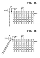
- Figs. 4A and 4B show the relationship between the ink-jet head 55 and color elements 401 of the color filter portion 54 formed on the substrate (glass plate) 53.
- Fig. 4A illustrates a case wherein the ink-jet head 55 is located to be substantially parallel to the longitudinal (Y) direction of the color elements 401
- Fig. 4B illustrates a case wherein the ink-jet head 55 is inclined with respect to the longitudinal (Y) direction of the color elements 401.
- Figs. 4A and 4B illustrate only the ink-jet head for one color, and do not illustrate other color heads.
- the inclination of the ink-jet head 55 relative to the Y direction of the color elements by a predetermined amount, as shown in Fig. 4B, is attained by rotating the XY ⁇ stage 52 by the stage control unit 71 in this embodiment. However, the ink-jet head 55 itself may be inclined.
- the color elements 401 of the color filter are arranged at pitches of about 100 ⁇ m in the X direction and about 300 ⁇ m in the Y direction, and arrays of color elements are formed in the order of R, G, and B from the left end (Figs. 4A and 4B) of the color filter.
- the nozzle pitch of the ink-jet head 55 is about 70.5 ⁇ m. Therefore, in the case of Fig. 4A, each color element 401 is formed by about three to four dots (ink), and in the case of Fig. 4B, one color element 401 is formed by dots (ink) more than those in Fig. 4A.
- ink may be ejected from odd-numbered nozzles in the first pass, and may be ejected from even-numbered nozzles in the second pass (2 path method).
- Figs. 5A to 5F are views for explaining the manufacturing process of the color filter in this embodiment. Note that Figs. 5A to 5F exemplify a case wherein a resin composition layer 3 for receiving ink is formed on a glass substrate 1.
- the present invention is not limited to this specific structure.
- color elements may be formed by directly supplying ink onto the glass substrate 1 (53).
- Fig. 5A shows the glass substrate 1 comprising light-transmitting portions 9 (portions to be colored) and a black matrix 2 that constitutes light-shielding portions 10. Note that the black matrix 2 is not always required.
- the substrate 1 formed with the black matrix 2 is coated with a resin composition, which is pre-baked as needed to form the resin composition layer 3 (Fig. 5B).
- This resin composition itself has poor ink receptivity, but is imparted with ink affinity under a given condition (e.g., light irradiation or light irradiation and heating) and is set under another condition.
- the resin composition layer 3 may be formed by various coating methods such as a spin coating method, a roll coating method, a bar coating method, a spray coating method, a dip coating method, and the like, and the method to be used is not particularly limited.
- resin layer portions on the light-transmitting portions 9 are subjected to pattern exposure, so that non-masked resin layer portions are imparted ink affinity (Fig. 5C), thereby forming portions 6 with ink affinity (exposed portions) and portions 5 without ink affinity (masked portions) on the resin composition layer 3 (Fig. 5D).
- R (red), G (green), and B (blue) color ink are ejected from the ink-jet head 55 onto the resin composition layer 3 to color the portions 6 (Fig. 5E), and the ink is dried as needed.
- the ink-jet method in this case, a thermal energy method and a mechanical energy method are known, and either of these methods can be suitably used.
- the type of the ink to be used is not particularly limited as long as that being able to be used as one for the ink-jet method.
- coloring agents coloring agents that match transmission spectra required for the individual R, G, and B pixels are appropriately selected from various kinds of pigments or dyes.
- a light irradiation or light irradiation & heat treatment is performed to set the colored resin composition layer 3, and a protection layer 8 is coated on the surface of the layer 3 as needed (Fig. 5F).
- a condition different from that for the above-mentioned ink affinity treatment e.g., a method of increasing the exposure amount upon light irradiation, a method of changing the heating condition, a method of using both light irradiation and heat treatments, or the like may be adopted.
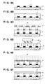
- Figs. 6A to 6F show another manufacturing process of the color filter.
- Fig. 6A shows a glass substrate 1 comprising light-transmitting portions 7 and a black matrix 2 serving as light-shielding portions.
- the substrate 1 formed with the black matrix 2 is coated with a resin composition, which is pre-baked as needed to form a resin layer 3 (Fig. 6B).
- the resin composition can be set by light irradiation or light irradiation and heating, and has ink receptivity.
- the resin composition layer 3 may be formed by various coating methods such as spin coating method, roll coating method, bar coating method, spray coating method, dip coating method, and the like, and the method to be used is not particularly limited.
- portions, corresponding to the light-shielding portions of the black matrix 2, of the resin layer 3 are subjected to pattern exposure in advance using a photomask 4, and are set to form portions 5 (non-colored portions) which do not absorb any ink (Fig. 6C).
- portions 5 non-colored portions which do not absorb any ink
- Fig. 6D portions 5 (non-colored portions) which do not absorb any ink
- a mask having aperture portions for setting the light-shielding portions of the black matrix 2 is used.
- a relatively large amount of ink must be supplied.
- a mask 4 having aperture portions narrower than the (light-shielding) widths of the black matrix 2 is preferably used.
- both dye- and pigment-based ink may be used, and both liquid and solid ink may be used.
- the present invention is not particularly limited to a specific one as long as the resin has ink receptivity, and can be set by light irradiation or at least one treatment of light irradiation and heating.
- the resin for example, an acrylic resin, epoxy resin, silicone resin, cellulosics such as hydroxypropyl cellulose, hydroxyethyl cellulose, methyl cellulose, carboxymethylcellulose, and the like or their modified substances, and the like may be used.
- a light initiator (crosslinking agent) may be used.
- a dichromate, a bisazide, a radical-based initiator, a cation-based initiator, an anion-based initiator, and the like may be used.
- these light initiators may be mixed or may be used in combination with other sensitizing agents.
- a photo-acid generation agent such as an onium salt may be used as a crosslinking agent together.
- a heat treatment may be performed after light irradiation.
- the resin layer containing such compositions has very high heat and water resistances, it can sufficiently withstand a high-temperature or washing process to be performed later.
- a bubble-jet type using electro-thermal energy converting elements as energy generation elements a piezo-jet type using piezoelectric elements, or the like may be used, and the coloring area and coloring pattern may be arbitrarily set.
- the black matrix 2 is formed.
- This black matrix may be formed on the resin layer after a set-able resin composition layer is formed or after coloring, and its pattern is not limited to that of this example.
- a metal thin film be formed on the substrate 1 by sputtering or deposition, and be patterned by a photolithography process.
- the present invention is not limited to this particular method.
- a heat treatment or a light irradiation & heat treatment is performed to set the set-able resin composition (Fig. 6E), and a protection layer 8 is formed (Fig. 6F) as needed.
- hv in Figs. 6C and 6E represents the light intensity, and in the case of the heat treatment, heat is applied in place of light.
- protection layer 8 arbitrary layers may be used as long as they can be formed using a photosetting type, a thermo-setting type, or photo-/thermosetting type second resin composition, or can be formed using an inorganic material by deposition or sputtering, have transparency as a constituting element of the color filter, and can sufficiently withstand an ITO formation process, an orientation film formation process, or the like to be performed later.
- Fig. 7 is a flow chart showing the color filter manufacturing processing in the color filter manufacturing apparatus 90 of this embodiment.
- the control program which executes this processing is stored in the ROM 67 shown in Fig. 2, and is executed under the control of the CPU 66.
- the longitudinal direction of the heads 55 is set to be parallel to the Y direction, as shown in, e.g., Fig. 4A, or the heads 55 are inclined by a predetermined amount with respect to the Y direction by setting the relative angle between the heads 55 and the XY ⁇ table 52 as shown in Fig. 4B when a larger number of dots is designated (this state is attained by rotating the XY ⁇ table 52 or the heads 55). In this manner, the initial position of the XY ⁇ table 52 is determined.
- step S2 The flow then advances to step S2, and the XY ⁇ table 52 begins to move in the -X direction. It is then checked in step S3 if the ink ejection timing of the R head has reached, i.e., the corresponding nozzles of the R head have reached a position where R color elements are to be formed. This checking step is attained based on the initial position and moving amount of the XY ⁇ table 52, the positions of the color ink-jet heads 55, and their nozzle positions. If it is determined in step S3 that the ink ejection timing of the R head has been reached, the flow advances to step S4, and ink is ejected from a plurality of corresponding nozzles of the R head to form R color elements.
- ink may be ejected from only one nozzle of the R head instead of a plurality of nozzles upon an ink ejection.
- one color element 401 may not be formed by a single ink ejection operation, but may be formed by a plurality of ink ejection operations. The same applies to the G and B colors to be described below.
- step S5 It is checked in step S5, as in step S3 above, if the G head has reached the position of G color elements of the color filter portion 54. If YES in step S5, the flow advances to step S6, and ink is ejected using corresponding nozzles of the G head as in step S4 above. Furthermore, it is similarly determined in step S7 whether the ejection timing of ink from the B head has been reached. If YES in step S7, the flow advances to step S8, and ink is ejected from the corresponding nozzles of the B head as in step S4 or S6 above, thus forming B color elements. Thereafter, the flow advances to step S9 to check if a single scan operation in the X direction has been completed. If NO in step S9, the flow advances to step S2 to execute the above-mentioned processing.
- step S9 the flow advances to step S10 to check if all the intended color elements are formed on the substrate 53 shown in Fig. 1. If YES in step S10, the processing ends; otherwise, the flow advances to step S11, and the XY ⁇ stage 52 is moved in the -Y direction. In step S12, the relative moving direction between the heads 55 and the XY ⁇ table 52 is set in a direction opposite to that in the above processing (i.e., a direction opposite to the X direction indicated by an arrow in Fig. 4A). Thereafter, the flow returns to step S2.
- the moving amount, in the Y direction, of the table 52 in step S11 varies depending on, e.g., the degree of overlapping of dots in the Y direction, the interval, in the Y direction, of the color elements 401, and the like. Also, when color elements are formed by relatively moving the heads and the table in a direction opposite to the X direction, the driving timings of the nozzles of the respective heads are adjusted in correspondence with the positions of the heads and their inclination, as a matter of course.
- Fig. 8 is a sectional view showing the basic arrangement of a display screen of a color liquid crystal display 30 which incorporates the above-mentioned color filter.
- Reference numeral 11 denotes a polarizing plate; 1, a transparent substrate such as glass; 2, a black matrix; 3, a resin composition layer; 8, a protection layer; 16, a common electrode; 17, an orientation film; 18, a liquid crystal compound; 19, an orientation film; 20, pixel electrodes; 21, a glass substrate; 22, a polarizing plate; and 23, backlight light.
- Reference numeral 53 denotes the color filter mentioned above; and 24, a counter substrate.
- the color filter 53 and the counter substrate 24 are fitted with each other, the liquid crystal compound 18 is sealed therebetween, and transparent pixel electrodes 20 are formed in a matrix on the inner surface of the substrate 21 that opposes the color filter 53.
- the color filter 53 is arranged, so that R, G, and B pixels are aligned at the positions of the pixel electrodes 20.
- orientation films 17 and 19 are formed on the inner surfaces of the substrates 1 and 21, and by a rubbing treatment of these films, liquid crystal molecules align in a predetermined direction.
- the polarizing plates 11 and 22 are adhered on the outer surfaces of the substrates 1 and 21, and a combination of a fluorescent lamp and a scattering plate (neither are shown) is normally used as a backlight.
- a display operation is attained in such a manner that the liquid crystal compound 18 serves as an optical shutter for changing the transmittance of the backlight light 23.
- the black matrix 2 is formed on the glass substrate 1 side.
- the present invention is not limited to this structure.
- the black matrix 2 may be formed on the glass substrate 21 of the counter substrate 24.
- Fig. 9 is a schematic block diagram showing the arrangement used when the above-mentioned liquid crystal display is applied to an information processing apparatus having functions of a wordsprocessor, a personal computer, a facsimile apparatus, and a copying machine.
- reference numeral 1801 denotes a control unit for controlling the entire apparatus.
- the control unit 1801 comprises a CPU such as a microprocessor or the like, and various I/O ports, and makes control by outputting control signals, data signals, and the like to the respective units, and receiving control signals and data signals from the respective units.
- Reference numeral 1802 denotes a display for displaying various menus, document information, image data read by an image reader 1807, and the like on its display screen.
- Reference numeral 1803 denotes a touch panel arranged on the display 1802. When a user presses the surface of the touch panel 1803 with, e.g., his or her finger, he or she can input an item, coordinate position, and the like on the display 1802.
- Reference numeral 1804 denotes an FM (Frequency Modulation) sound source unit which stores music information created by, e.g., a music editor or the like in a memory 1810 or an external storage device 1812 as digital data, and FM-modulates the digital data read out from the memory or the like.
- An electrical signal from the FM sound source unit 1804 is converted into audible tones via a loudspeaker 1805.
- a printer 1806 is used as an output terminal for the wordprocessor, personal computer, facsimile apparatus, and copying machine.
- Reference numeral 1807 denotes an image reader for photoelectrically reading original data and inputting read original data.
- the image reader 1807 is arranged in the middle of an original convey path, and reads various kinds of originals such as facsimile originals, copy originals, and the like.
- Reference numeral 1808 denotes a facsimile (FAX) transmission/reception unit for performing facsimile-transmission of original data read by the image reader 1807, and receiving and decoding an incoming facsimile signal.
- the FAX transmission/reception unit 1808 has an interface function with external devices.
- Reference numeral 1809 denotes a telephone set having various telephone functions such as a normal telephone function, an automatic answering telephone function, and the like.
- Reference numeral 1810 denotes a memory which includes a ROM for storing a system program, a manager program, other application program, character fonts, dictionaries, and the like, a RAM for storing an application program, document information, video information, and the like loaded from the external storage device 1812, and the like.
- Reference numeral 1811 denotes a keyboard for inputting document information, various commands, and the like.
- Reference numeral 1812 denotes an external storage device using, as storage media, a floppy disk, a hard disk, and the like. The external storage device 1812 stores document information, music or voice information, user's application programs, and the like.
- Fig. 10 is a schematic perspective view of the information processing apparatus shown in Fig. 9.
- reference numeral 1802 denotes a flat panel display which utilizes the above-mentioned liquid crystal display, and displays various menus, figure information, document information, and the like.
- the coordinate input operation and the item designation input operation can be performed by pressing the surface of the-touch panel 1803 with a finger or the like.
- Reference numeral 1902 denotes a handset used when the apparatus serves as a telephone set.
- the keyboard 1811 has various function keys 1904 and the like.
- Reference numeral 1905 denotes an insertion slot of a floppy disk as one medium of the external storage device 1812.
- Reference numeral 1906 denotes a paper placing plate where an original to be read by the image reader 1807 is placed. The read original is exhausted from the rear portion of the apparatus. In a facsimile reception mode or the like, received data is printed by the ink-jet printer 1806.
- the information processing apparatus serves as a personal computer or wordprocessor
- various kinds of information input from the keyboard 1811 are processed by the control unit 1801 in accordance with a predetermined program, and are output as images via the printer 1806.
- facsimile information input from the FAX transmission/reception unit 1808 via a communication line is subjected to reception processing in accordance with a predetermined program, and is output as a received image via the printer 1806.
- an original image is read by the image reader 1807, and the read original data is supplied from the control unit 1801 to the printer 1806 and is output as a copy image.
- original data read by the image reader 1807 is subjected to transmission processing by the control unit 1801 in accordance with a predetermined program, and is transmitted onto the communication line via the FAX transmission/reception unit 1808.
- the above-mentioned information processing apparatus may have an integrated structure that incorporates the ink-jet printer 1806 therein, as shown in Fig. 11. In this case, the portability can be improved.
- the same reference numerals in Fig. 11 denote the same parts as in Fig. 10, and a detailed description thereof will be omitted.
- the present invention has exemplified a printer apparatus, which comprises means (e.g., an electro-thermal conversion element, laser beam, and the like) for generating heat energy as energy utilized upon execution of ink ejection, and causes a change in state of ink by the heat energy, among the ink-jet recording systems.
- means e.g., an electro-thermal conversion element, laser beam, and the like
- heat energy as energy utilized upon execution of ink ejection
- causes a change in state of ink by the heat energy among the ink-jet recording systems.
- the system is effective because, by applying at least one driving signal, which corresponds to recording information and gives a rapid temperature rise exceeding nucleus boiling, to each of electro-thermal conversion elements arranged in correspondence with a sheet or liquid channels holding a liquid (ink), heat energy is generated by the electro-thermal conversion element to effect film boiling on the heat acting surface of the recording head, and consequently, a bubble can be formed in the liquid (ink) in one-to-one correspondence with the driving signal.
- the driving signal is applied as a pulse signal, the growth and shrinkage of the bubble can be attained instantly and adequately to achieve ejection of the liquid (ink) with particularly high response characteristics.
- signals disclosed in U.S. Patent Nos. 4,463,359 and 4,345,262 are suitable. Note that further excellent recording can be performed by using the conditions described in U.S. Patent No. 4,313,124 of the invention which relates to the temperature rise rate of the heat acting surface.
- the arrangement of the recording head in addition to the arrangement as a combination of ejection ports, liquid channels, and electro-thermal conversion elements (linear liquid channels or right-angled liquid channels) as disclosed in the above specifications, the arrangement using U.S. Patent Nos. 4,558,333 and 4,459,600, which disclose the arrangement having a heat acting portion arranged in a flexed region is also included in the present invention.
- the present invention can be effectively applied to an arrangement based on Japanese Patent Laid-Open No. 59-123670 which discloses an arrangement using a slit common to a plurality of electro-thermal conversion elements as an ejection portion of the electro-thermal conversion elements, or Japanese Patent Laid-Open No. 59-138461 which discloses an arrangement having an opening for absorbing a pressure wave of heat energy in correspondence with an ejection portion.
- a full line type recording head having a length corresponding to the width of a maximum recording medium which can be printed by the recording apparatus, either the arrangement which satisfies the full-line length by combining a plurality of recording heads as disclosed in the above specification or the arrangement as a single recording head obtained by forming recording heads integrally can be used.
- the present invention is effective for a case using an exchangeable chip type recording head which can be electrically connected to the apparatus main body or can receive ink from the apparatus main body upon being mounted on the apparatus main body, or a cartridge type recording head in which an ink tank is integrally arranged on the recording head itself.
- recovery means for the recording head, preliminary auxiliary means, and the like provided as an arrangement of the print apparatus of the present invention since the effect of the present invention can be further stabilized.
- examples of such means include, for the recording head, capping means, cleaning means, pressurization or suction means, and preliminary heating means using electro-thermal conversion elements, another heating element, or a combination thereof. It is also effective for stable recording to execute a preliminary ejection mode which performs ejection independently of recording.
- ink is described as a liquid.
- the present invention may use even ink which is solid at room temperature or less and softens or liquefies at room temperature as long as the ink liquefies upon application of a use recording signal.
- ink which is solid in a non-use state and liquefies upon heating may be used.
- the present invention can be applied to a case wherein ink which liquefies upon application of heat energy, such as ink which liquefies upon application of heat energy according to a recording signal and is ejected in a liquid state, ink which begins to solidify when it reaches a recording medium, or the like, is used.
- ink may oppose electro-thermal conversion elements while being held in a liquid or solid state in recess portions of a porous sheet or through holes, as described in Japanese Patent Laid-Open No. 54-56847 or 60-71260.
- the above-mentioned film boiling system is most effective for the above-mentioned ink.
- the present invention may be applied to either a system constituted by a plurality of equipments or an apparatus consisting of a single equipment.
- the present invention may also be applied to a case wherein the invention is achieved by supplying a program that practices the present invention to the system or apparatus.
- a storage medium that stores a program according to the present invention constitutes the present invention. By reading out the program from the storage medium to the system or apparatus, the system or apparatus operates according to the readout program.
- a color or density unevenness caused by variations of ink ejection characteristics of the nozzles of the ink-jet heads can be prevented.
- color elements can be accurately formed at a desired density.
Landscapes
- Physics & Mathematics (AREA)
- Engineering & Computer Science (AREA)
- Quality & Reliability (AREA)
- General Physics & Mathematics (AREA)
- Optics & Photonics (AREA)
- Optical Filters (AREA)
- Ink Jet (AREA)
- Devices For Indicating Variable Information By Combining Individual Elements (AREA)
- Liquid Crystal (AREA)
Applications Claiming Priority (6)
| Application Number | Priority Date | Filing Date | Title |
|---|---|---|---|
| JP19639195 | 1995-08-01 | ||
| JP196391/95 | 1995-08-01 | ||
| JP19639195 | 1995-08-01 | ||
| JP19052696 | 1996-07-19 | ||
| JP190526/96 | 1996-07-19 | ||
| JP19052696A JP3159919B2 (ja) | 1995-08-01 | 1996-07-19 | カラーフィルタの製造装置及び製造方法及び着色むらの低減方法 |
Publications (3)
| Publication Number | Publication Date |
|---|---|
| EP0756933A2 true EP0756933A2 (de) | 1997-02-05 |
| EP0756933A3 EP0756933A3 (de) | 1997-08-13 |
| EP0756933B1 EP0756933B1 (de) | 2004-05-06 |
Family
ID=26506148
Family Applications (1)
| Application Number | Title | Priority Date | Filing Date |
|---|---|---|---|
| EP96305472A Expired - Lifetime EP0756933B1 (de) | 1995-08-01 | 1996-07-25 | Verfahren und Apparat zum Herstellen eines Farbfilters, diesen Farbfilter verwendende Anzeigevorrichtung und elektronische Apparatur mit dieser Anzeigevorrichtung |
Country Status (8)
| Country | Link |
|---|---|
| US (1) | US6604821B1 (de) |
| EP (1) | EP0756933B1 (de) |
| JP (1) | JP3159919B2 (de) |
| KR (1) | KR100202726B1 (de) |
| CN (1) | CN1149412C (de) |
| AT (1) | ATE265932T1 (de) |
| DE (1) | DE69632367T2 (de) |
| TW (1) | TW413661B (de) |
Cited By (4)
| Publication number | Priority date | Publication date | Assignee | Title |
|---|---|---|---|---|
| EP1004902A3 (de) * | 1998-11-27 | 2001-10-31 | Canon Kabushiki Kaisha | Verfahren und Vorrichtung zur Herstellung von Farbfiltern, Farbfilter und Anzeigevorrichtung |
| US6645029B2 (en) | 2000-02-21 | 2003-11-11 | Canon Kabushiki Kaisha | Color filter producing method and apparatus |
| US7014521B1 (en) * | 1999-08-05 | 2006-03-21 | Canon Kabushiki Kaisha | Display panel having a color filter and a protective layer of heat melted material and method of manufacturing the display panel |
| CN110553714A (zh) * | 2019-08-31 | 2019-12-10 | 深圳市广宁股份有限公司 | 智能振动增强现实测试方法及相关产品 |
Families Citing this family (30)
| Publication number | Priority date | Publication date | Assignee | Title |
|---|---|---|---|---|
| JP3332854B2 (ja) | 1997-06-17 | 2002-10-07 | キヤノン株式会社 | カラーフィルタの製造方法 |
| JP2001228320A (ja) | 2000-02-21 | 2001-08-24 | Canon Inc | カラーフィルタの製造方法及び製造装置 |
| JP2002221616A (ja) | 2000-11-21 | 2002-08-09 | Seiko Epson Corp | カラーフィルタの製造方法及び製造装置、液晶装置の製造方法及び製造装置、el装置の製造方法及び製造装置、インクジェットヘッドの制御装置、材料の吐出方法及び材料の吐出装置、並びに電子機器 |
| JP4834910B2 (ja) * | 2000-12-08 | 2011-12-14 | 大日本印刷株式会社 | カラーフィルタの製造方法 |
| JP4972820B2 (ja) * | 2000-12-08 | 2012-07-11 | 大日本印刷株式会社 | カラーフィルタの製造方法 |
| JP2002174719A (ja) * | 2000-12-08 | 2002-06-21 | Dainippon Printing Co Ltd | カラーフィルタの製造方法 |
| JP2003084125A (ja) * | 2001-07-04 | 2003-03-19 | Seiko Epson Corp | カラーフィルタの製造方法及び製造装置、液晶表示装置の製造方法及び製造装置、el発光層配設基板の製造方法及び製造装置、el発光装置の製造方法及び製造装置、成膜方法及び成膜装置、電気光学装置及びその製造方法並びに電子機器 |
| JP3932847B2 (ja) * | 2001-09-27 | 2007-06-20 | セイコーエプソン株式会社 | 有機el素子とその製造方法、及びelディスプレイ、電子機器 |
| JP2003159787A (ja) * | 2001-11-28 | 2003-06-03 | Seiko Epson Corp | 吐出方法およびその装置、電気光学装置、その製造方法およびその製造装置、カラーフィルタ、その製造方法およびその製造装置、ならびに基材を有するデバイス、その製造方法およびその製造装置 |
| US6736484B2 (en) * | 2001-12-14 | 2004-05-18 | Seiko Epson Corporation | Liquid drop discharge method and discharge device; electro optical device, method of manufacture thereof, and device for manufacture thereof; color filter method of manufacture thereof, and device for manufacturing thereof; and device incorporating backing, method of manufacturing thereof, and device for manufacture thereof |
| US6921148B2 (en) * | 2002-01-30 | 2005-07-26 | Seiko Epson Corporation | Liquid drop discharge head, discharge method and discharge device; electro optical device, method of manufacture thereof, and device for manufacture thereof; color filter, method of manufacture thereof, and device for manufacture thereof; and device incorporating backing, method of manufacture thereof, and device for manufacture thereof |
| JP3922177B2 (ja) | 2002-02-12 | 2007-05-30 | セイコーエプソン株式会社 | 成膜方法、成膜装置、液滴吐出装置、カラーフィルタの製造方法、表示装置の製造方法 |
| CN100409042C (zh) * | 2002-04-19 | 2008-08-06 | 精工爱普生株式会社 | 器件的制造方法、器件以及电子机器 |
| JP4378950B2 (ja) | 2002-12-24 | 2009-12-09 | セイコーエプソン株式会社 | 液滴吐出装置および電気光学装置の製造方法 |
| JP2005092049A (ja) * | 2003-09-19 | 2005-04-07 | Seiko Epson Corp | 吐出方法、レンズおよびその製造方法、半導体レーザおよびその製造方法、光学装置、ならびに吐出装置 |
| JP2005221654A (ja) | 2004-02-04 | 2005-08-18 | Seiko Epson Corp | 色要素付き基板、色要素付き基板の製造方法および電子機器 |
| JP4100354B2 (ja) * | 2004-02-19 | 2008-06-11 | セイコーエプソン株式会社 | 材料塗布方法、カラーフィルタの製造方法、エレクトロルミネッセンス表示装置の製造方法、およびプラズマ表示装置の製造方法。 |
| JP4604559B2 (ja) * | 2004-06-02 | 2011-01-05 | 凸版印刷株式会社 | カラーフィルタ及びその製造方法 |
| JP4746305B2 (ja) * | 2004-10-28 | 2011-08-10 | 株式会社アルバック | ヘッドモジュール |
| US20060093751A1 (en) * | 2004-11-04 | 2006-05-04 | Applied Materials, Inc. | System and methods for inkjet printing for flat panel displays |
| JP4029895B2 (ja) | 2004-12-08 | 2008-01-09 | セイコーエプソン株式会社 | 液滴吐出装置、液滴吐出方法、電気光学装置の製造方法、電気光学装置および電子機器 |
| JP2007244977A (ja) * | 2006-03-15 | 2007-09-27 | Seiko Epson Corp | 液状体配置方法および電気光学装置の製造方法、並びに電気光学装置、電子機器 |
| KR101253060B1 (ko) * | 2006-06-22 | 2013-04-10 | 삼성디스플레이 주식회사 | 컬러필터 기판의 제조 방법 |
| JP5292677B2 (ja) * | 2006-07-07 | 2013-09-18 | 凸版印刷株式会社 | 光学素子の製造方法、カラーフィルタの製造方法及び有機エレクトロルミネッセンス素子の製造方法 |
| JP2008015308A (ja) * | 2006-07-07 | 2008-01-24 | Toppan Printing Co Ltd | 光学素子の製造方法、カラーフィルタの製造方法及び有機エレクトロルミネッセンス素子の製造方法。 |
| JP4983128B2 (ja) * | 2006-07-25 | 2012-07-25 | 凸版印刷株式会社 | 光学素子の製造方法、カラーフィルタの製造方法及び有機エレクトロルミネッセンス素子の製造方法 |
| JP5233099B2 (ja) * | 2006-08-31 | 2013-07-10 | 凸版印刷株式会社 | 光学素子の製造方法、カラーフィルタの製造方法及び有機エレクトロルミネッセンス素子の製造方法 |
| JP2009109799A (ja) * | 2007-10-31 | 2009-05-21 | Toray Eng Co Ltd | 塗布装置及び塗布方法 |
| JP2012252182A (ja) * | 2011-06-03 | 2012-12-20 | Nippon Steel & Sumikin Chemical Co Ltd | カラーフィルターの製造方法、カラーフィルター、及び反射型表示装置 |
| CN110231672B (zh) * | 2018-02-28 | 2021-08-10 | 张家港康得新光电材料有限公司 | 滤光片模组的制备方法及制备系统 |
Family Cites Families (32)
| Publication number | Priority date | Publication date | Assignee | Title |
|---|---|---|---|---|
| CA1127227A (en) | 1977-10-03 | 1982-07-06 | Ichiro Endo | Liquid jet recording process and apparatus therefor |
| JPS5936879B2 (ja) | 1977-10-14 | 1984-09-06 | キヤノン株式会社 | 熱転写記録用媒体 |
| JPS54158232A (en) * | 1978-06-05 | 1979-12-13 | Oki Electric Ind Co Ltd | Multi-nozzle ink jet printer of variable resolution |
| US4330787A (en) | 1978-10-31 | 1982-05-18 | Canon Kabushiki Kaisha | Liquid jet recording device |
| US4345262A (en) | 1979-02-19 | 1982-08-17 | Canon Kabushiki Kaisha | Ink jet recording method |
| US4463359A (en) | 1979-04-02 | 1984-07-31 | Canon Kabushiki Kaisha | Droplet generating method and apparatus thereof |
| US4313124A (en) | 1979-05-18 | 1982-01-26 | Canon Kabushiki Kaisha | Liquid jet recording process and liquid jet recording head |
| US4558333A (en) | 1981-07-09 | 1985-12-10 | Canon Kabushiki Kaisha | Liquid jet recording head |
| JPS59123670A (ja) | 1982-12-28 | 1984-07-17 | Canon Inc | インクジエツトヘツド |
| JPS59138461A (ja) | 1983-01-28 | 1984-08-08 | Canon Inc | 液体噴射記録装置 |
| JPS6071260A (ja) | 1983-09-28 | 1985-04-23 | Erumu:Kk | 記録装置 |
| DE3477118D1 (en) * | 1984-04-27 | 1989-04-13 | Siemens Ag | Ink-writing apparatus reproducing multicolour characters and/or patterns |
| JPS6157814A (ja) * | 1984-08-29 | 1986-03-24 | Hitachi Ltd | 電子計器盤 |
| JPS63235901A (ja) * | 1987-03-24 | 1988-09-30 | Fujitsu Ltd | カラ−フイルタの形成方法 |
| US5285298A (en) * | 1988-07-29 | 1994-02-08 | Canon Kabushiki Kaisha | Color display apparatus |
| JPH02173704A (ja) | 1988-12-27 | 1990-07-05 | Seiko Epson Corp | カラーフィルタの製造方法 |
| US4965593A (en) * | 1989-07-27 | 1990-10-23 | Hewlett-Packard Company | Print quality of dot printers |
| US5079571A (en) * | 1990-05-25 | 1992-01-07 | Tektronix, Inc. | Interlaced printing using spaced print arrays |
| JPH04261503A (ja) | 1991-02-15 | 1992-09-17 | Kyodo Printing Co Ltd | カラーフィルタの製造方法 |
| US5430469A (en) * | 1991-06-05 | 1995-07-04 | Canon Kabushiki Kaisha | Tone recording method using ink recording head |
| JP2951041B2 (ja) | 1991-06-06 | 1999-09-20 | キヤノン株式会社 | 記録装置および記録方法 |
| JP2891799B2 (ja) * | 1991-06-07 | 1999-05-17 | キヤノン株式会社 | インクジェット記録方法 |
| JPH05301379A (ja) | 1991-07-02 | 1993-11-16 | Ricoh Co Ltd | 記録ヘッド |
| JPH0531920A (ja) * | 1991-08-01 | 1993-02-09 | Canon Inc | インクジエツト記録装置 |
| JPH0671879A (ja) | 1992-08-27 | 1994-03-15 | Rohm Co Ltd | インクジェットプリンタ |
| JP3087442B2 (ja) * | 1992-04-10 | 2000-09-11 | ブラザー工業株式会社 | 印字装置 |
| EP0605685B1 (de) * | 1992-06-01 | 1999-10-13 | Advanced Technology Incubator, Inc. | Lichtsteuerelement für hochauflösende optische systeme und verfahren zu seiner herstellung |
| JP3572629B2 (ja) | 1993-06-15 | 2004-10-06 | 大日本インキ化学工業株式会社 | 印刷制御方法 |
| US5485183A (en) * | 1993-06-30 | 1996-01-16 | Dataproducts Corporation | Interlaced dot-on-dot printing |
| JP3332515B2 (ja) | 1993-11-24 | 2002-10-07 | キヤノン株式会社 | カラーフィルタ、その製造方法及び液晶パネル |
| FR2716010B1 (fr) | 1994-02-04 | 1996-04-19 | Toxot Science & Appl | Dispositif et procédés de fabrication et de réparation de filtres colorés. |
| JP2839133B2 (ja) * | 1994-03-31 | 1998-12-16 | キヤノン株式会社 | カラーフィルタの製造方法及び製造装置及び液晶表示装置の製造方法及び液晶表示装置を備えた装置の製造方法 |
-
1996
- 1996-07-19 JP JP19052696A patent/JP3159919B2/ja not_active Expired - Fee Related
- 1996-07-23 TW TW085108956A patent/TW413661B/zh not_active IP Right Cessation
- 1996-07-25 EP EP96305472A patent/EP0756933B1/de not_active Expired - Lifetime
- 1996-07-25 DE DE69632367T patent/DE69632367T2/de not_active Expired - Lifetime
- 1996-07-25 AT AT96305472T patent/ATE265932T1/de not_active IP Right Cessation
- 1996-07-30 US US08/689,113 patent/US6604821B1/en not_active Expired - Fee Related
- 1996-07-31 KR KR1019960031822A patent/KR100202726B1/ko not_active Expired - Fee Related
- 1996-08-01 CN CNB961122544A patent/CN1149412C/zh not_active Expired - Fee Related
Cited By (5)
| Publication number | Priority date | Publication date | Assignee | Title |
|---|---|---|---|---|
| EP1004902A3 (de) * | 1998-11-27 | 2001-10-31 | Canon Kabushiki Kaisha | Verfahren und Vorrichtung zur Herstellung von Farbfiltern, Farbfilter und Anzeigevorrichtung |
| US6540346B1 (en) | 1998-11-27 | 2003-04-01 | Canon Kabushiki Kaisha | Color filter manufacturing apparatus and method, color filter, display device, apparatus having the display device, and method of reducing unevenness of discharge volume in plural nozzles by ink circulation |
| US7014521B1 (en) * | 1999-08-05 | 2006-03-21 | Canon Kabushiki Kaisha | Display panel having a color filter and a protective layer of heat melted material and method of manufacturing the display panel |
| US6645029B2 (en) | 2000-02-21 | 2003-11-11 | Canon Kabushiki Kaisha | Color filter producing method and apparatus |
| CN110553714A (zh) * | 2019-08-31 | 2019-12-10 | 深圳市广宁股份有限公司 | 智能振动增强现实测试方法及相关产品 |
Also Published As
| Publication number | Publication date |
|---|---|
| TW413661B (en) | 2000-12-01 |
| EP0756933A3 (de) | 1997-08-13 |
| ATE265932T1 (de) | 2004-05-15 |
| CN1167925A (zh) | 1997-12-17 |
| JP3159919B2 (ja) | 2001-04-23 |
| DE69632367T2 (de) | 2005-05-04 |
| KR100202726B1 (ko) | 1999-06-15 |
| JPH09101412A (ja) | 1997-04-15 |
| DE69632367D1 (de) | 2004-06-09 |
| CN1149412C (zh) | 2004-05-12 |
| EP0756933B1 (de) | 2004-05-06 |
| KR970010116A (ko) | 1997-03-27 |
| US6604821B1 (en) | 2003-08-12 |
Similar Documents
| Publication | Publication Date | Title |
|---|---|---|
| US6604821B1 (en) | Method and apparatus for manufacturing color filter, display device using the color filter, and electronic equipment comprising the display device | |
| EP0761440B1 (de) | Verfahren und Gerät zum Tintenstrahldrucken und Verfahren und Gerät zur Herstellung von Farbfiltern | |
| EP1074862B1 (de) | Herstellung von Farbfiltern | |
| JP2839133B2 (ja) | カラーフィルタの製造方法及び製造装置及び液晶表示装置の製造方法及び液晶表示装置を備えた装置の製造方法 | |
| EP0756932B1 (de) | Verfahren zum Herstellen eines Farbfilters, Farbfilter, Anzeigevorrichtung und Apparat mit dieser Anzeigevorrichtung | |
| JP3059678B2 (ja) | カラーフィルタの製造方法及び製造装置 | |
| JP3697131B2 (ja) | カラーフィルタの製造方法、製造装置、カラーフィルタを備えた表示装置の製造方法及び該表示装置を備えた装置の製造方法 | |
| JP3121226B2 (ja) | カラーフィルタの製造方法及びカラーフィルタの製造装置及び液晶表示装置の製造方法及び液晶表示装置を備えた装置の製造方法 | |
| JP3124718B2 (ja) | カラーフィルタの製造方法及び製造装置及びカラーフィルタのフィルタエレメント列内の着色ムラを低減する方法 | |
| JP2001228320A (ja) | カラーフィルタの製造方法及び製造装置 | |
| JPH07318724A (ja) | カラーフィルタの修正方法及び修正装置及びカラーフィルタ及び液晶表示装置及びこの液晶表示装置を備えた装置 | |
| KR100255838B1 (ko) | 잉크 토출 밀도 설정 방법, 컬러 필터 제조 방법, 컬러 필터,표시 장치 및 표시 장치를 갖는 장치 | |
| EP0790509A2 (de) | Herstellungsverfahren für ein Farbfilter und dafür geeignete Anordnung, Farbfilter, Anzeigevorrichtung und diese enthaltendes Gerät | |
| JP3413164B2 (ja) | カラーフィルタの製造方法及び製造装置及び液晶表示装置の製造方法及び液晶表示装置を備えた装置の製造方法 | |
| JPH08271724A (ja) | カラーフィルタの製造装置及び製造方法及びカラーフィルタ及び液晶表示装置及びこの液晶表示装置を備えた装置 | |
| JP2000284113A (ja) | カラーフィルタの製造方法及びカラーフィルタ及び表示装置及びこの表示装置を備えた装置 | |
| JP3100918B2 (ja) | カラーフィルタの製造方法及び製造装置及び表示装置の製造方法及び表示装置を備えた装置の製造方法 | |
| JPH112711A (ja) | カラーフィルタの製造方法及びカラーフィルタ及び表示装置及びこの表示装置を備えた装置 | |
| JPH1114820A (ja) | カラーフィルタの製造方法及び製造装置及びカラーフィルタ及び表示装置及びこの表示装置を備えた装置 | |
| JPH1130713A (ja) | カラーフィルタの製造方法及び製造装置及びカラーフィルタ及び表示装置及びこの表示装置を備えた装置 | |
| JPH10250117A (ja) | カラーフィルタの製造装置及び製造方法及びカラーフィルタ及び表示装置及びこの表示装置を備えた装置 | |
| JPH08292312A (ja) | カラーフィルタの修正方法および修正装置及びカラーフィルタ及び液晶表示装置及びこの液晶表示装置を備えた装置 | |
| JPH0973013A (ja) | カラーフィルタの製造方法及び製造装置 |
Legal Events
| Date | Code | Title | Description |
|---|---|---|---|
| PUAI | Public reference made under article 153(3) epc to a published international application that has entered the european phase |
Free format text: ORIGINAL CODE: 0009012 |
|
| AK | Designated contracting states |
Kind code of ref document: A2 Designated state(s): AT BE CH DE DK ES FI FR GB GR IE IT LI LU NL PT SE |
|
| PUAL | Search report despatched |
Free format text: ORIGINAL CODE: 0009013 |
|
| AK | Designated contracting states |
Kind code of ref document: A3 Designated state(s): AT BE CH DE DK ES FI FR GB GR IE IT LI LU NL PT SE |
|
| 17P | Request for examination filed |
Effective date: 19971224 |
|
| 17Q | First examination report despatched |
Effective date: 19990713 |
|
| GRAP | Despatch of communication of intention to grant a patent |
Free format text: ORIGINAL CODE: EPIDOSNIGR1 |
|
| GRAS | Grant fee paid |
Free format text: ORIGINAL CODE: EPIDOSNIGR3 |
|
| GRAA | (expected) grant |
Free format text: ORIGINAL CODE: 0009210 |
|
| AK | Designated contracting states |
Kind code of ref document: B1 Designated state(s): AT BE CH DE DK ES FI FR GB GR IE IT LI LU NL PT SE |
|
| PG25 | Lapsed in a contracting state [announced via postgrant information from national office to epo] |
Ref country code: LI Free format text: LAPSE BECAUSE OF FAILURE TO SUBMIT A TRANSLATION OF THE DESCRIPTION OR TO PAY THE FEE WITHIN THE PRESCRIBED TIME-LIMIT Effective date: 20040506 Ref country code: FI Free format text: LAPSE BECAUSE OF FAILURE TO SUBMIT A TRANSLATION OF THE DESCRIPTION OR TO PAY THE FEE WITHIN THE PRESCRIBED TIME-LIMIT Effective date: 20040506 Ref country code: CH Free format text: LAPSE BECAUSE OF FAILURE TO SUBMIT A TRANSLATION OF THE DESCRIPTION OR TO PAY THE FEE WITHIN THE PRESCRIBED TIME-LIMIT Effective date: 20040506 Ref country code: BE Free format text: LAPSE BECAUSE OF FAILURE TO SUBMIT A TRANSLATION OF THE DESCRIPTION OR TO PAY THE FEE WITHIN THE PRESCRIBED TIME-LIMIT Effective date: 20040506 Ref country code: AT Free format text: LAPSE BECAUSE OF FAILURE TO SUBMIT A TRANSLATION OF THE DESCRIPTION OR TO PAY THE FEE WITHIN THE PRESCRIBED TIME-LIMIT Effective date: 20040506 |
|
| REG | Reference to a national code |
Ref country code: GB Ref legal event code: FG4D |
|
| REG | Reference to a national code |
Ref country code: CH Ref legal event code: EP |
|
| REF | Corresponds to: |
Ref document number: 69632367 Country of ref document: DE Date of ref document: 20040609 Kind code of ref document: P |
|
| REG | Reference to a national code |
Ref country code: IE Ref legal event code: FG4D |
|
| PG25 | Lapsed in a contracting state [announced via postgrant information from national office to epo] |
Ref country code: LU Free format text: LAPSE BECAUSE OF NON-PAYMENT OF DUE FEES Effective date: 20040725 |
|
| PG25 | Lapsed in a contracting state [announced via postgrant information from national office to epo] |
Ref country code: IE Free format text: LAPSE BECAUSE OF NON-PAYMENT OF DUE FEES Effective date: 20040726 |
|
| PG25 | Lapsed in a contracting state [announced via postgrant information from national office to epo] |
Ref country code: SE Free format text: LAPSE BECAUSE OF FAILURE TO SUBMIT A TRANSLATION OF THE DESCRIPTION OR TO PAY THE FEE WITHIN THE PRESCRIBED TIME-LIMIT Effective date: 20040806 Ref country code: GR Free format text: LAPSE BECAUSE OF FAILURE TO SUBMIT A TRANSLATION OF THE DESCRIPTION OR TO PAY THE FEE WITHIN THE PRESCRIBED TIME-LIMIT Effective date: 20040806 Ref country code: DK Free format text: LAPSE BECAUSE OF FAILURE TO SUBMIT A TRANSLATION OF THE DESCRIPTION OR TO PAY THE FEE WITHIN THE PRESCRIBED TIME-LIMIT Effective date: 20040806 |
|
| PG25 | Lapsed in a contracting state [announced via postgrant information from national office to epo] |
Ref country code: ES Free format text: LAPSE BECAUSE OF FAILURE TO SUBMIT A TRANSLATION OF THE DESCRIPTION OR TO PAY THE FEE WITHIN THE PRESCRIBED TIME-LIMIT Effective date: 20040817 |
|
| REG | Reference to a national code |
Ref country code: CH Ref legal event code: PL |
|
| ET | Fr: translation filed | ||
| PLBE | No opposition filed within time limit |
Free format text: ORIGINAL CODE: 0009261 |
|
| STAA | Information on the status of an ep patent application or granted ep patent |
Free format text: STATUS: NO OPPOSITION FILED WITHIN TIME LIMIT |
|
| 26N | No opposition filed |
Effective date: 20050208 |
|
| REG | Reference to a national code |
Ref country code: IE Ref legal event code: MM4A |
|
| PG25 | Lapsed in a contracting state [announced via postgrant information from national office to epo] |
Ref country code: PT Free format text: LAPSE BECAUSE OF NON-PAYMENT OF DUE FEES Effective date: 20041006 |
|
| PGFP | Annual fee paid to national office [announced via postgrant information from national office to epo] |
Ref country code: NL Payment date: 20140630 Year of fee payment: 19 Ref country code: DE Payment date: 20140731 Year of fee payment: 19 |
|
| PGFP | Annual fee paid to national office [announced via postgrant information from national office to epo] |
Ref country code: GB Payment date: 20140724 Year of fee payment: 19 Ref country code: FR Payment date: 20140728 Year of fee payment: 19 |
|
| PGFP | Annual fee paid to national office [announced via postgrant information from national office to epo] |
Ref country code: IT Payment date: 20140702 Year of fee payment: 19 |
|
| REG | Reference to a national code |
Ref country code: DE Ref legal event code: R119 Ref document number: 69632367 Country of ref document: DE |
|
| GBPC | Gb: european patent ceased through non-payment of renewal fee |
Effective date: 20150725 |
|
| REG | Reference to a national code |
Ref country code: NL Ref legal event code: MM Effective date: 20150801 |
|
| PG25 | Lapsed in a contracting state [announced via postgrant information from national office to epo] |
Ref country code: DE Free format text: LAPSE BECAUSE OF NON-PAYMENT OF DUE FEES Effective date: 20160202 Ref country code: GB Free format text: LAPSE BECAUSE OF NON-PAYMENT OF DUE FEES Effective date: 20150725 Ref country code: IT Free format text: LAPSE BECAUSE OF NON-PAYMENT OF DUE FEES Effective date: 20150725 |
|
| REG | Reference to a national code |
Ref country code: FR Ref legal event code: ST Effective date: 20160331 |
|
| PG25 | Lapsed in a contracting state [announced via postgrant information from national office to epo] |
Ref country code: NL Free format text: LAPSE BECAUSE OF NON-PAYMENT OF DUE FEES Effective date: 20150801 Ref country code: FR Free format text: LAPSE BECAUSE OF NON-PAYMENT OF DUE FEES Effective date: 20150731 |