EP0754841A1 - Procédé et dispositif de purification des gaz d'échappement de véhicules à moteur - Google Patents
Procédé et dispositif de purification des gaz d'échappement de véhicules à moteur Download PDFInfo
- Publication number
- EP0754841A1 EP0754841A1 EP96111786A EP96111786A EP0754841A1 EP 0754841 A1 EP0754841 A1 EP 0754841A1 EP 96111786 A EP96111786 A EP 96111786A EP 96111786 A EP96111786 A EP 96111786A EP 0754841 A1 EP0754841 A1 EP 0754841A1
- Authority
- EP
- European Patent Office
- Prior art keywords
- adsorber
- exhaust gas
- gas flow
- catalytic converter
- flaps
- Prior art date
- Legal status (The legal status is an assumption and is not a legal conclusion. Google has not performed a legal analysis and makes no representation as to the accuracy of the status listed.)
- Granted
Links
Images

Classifications
-
- F—MECHANICAL ENGINEERING; LIGHTING; HEATING; WEAPONS; BLASTING
- F01—MACHINES OR ENGINES IN GENERAL; ENGINE PLANTS IN GENERAL; STEAM ENGINES
- F01N—GAS-FLOW SILENCERS OR EXHAUST APPARATUS FOR MACHINES OR ENGINES IN GENERAL; GAS-FLOW SILENCERS OR EXHAUST APPARATUS FOR INTERNAL COMBUSTION ENGINES
- F01N3/00—Exhaust or silencing apparatus having means for purifying, rendering innocuous, or otherwise treating exhaust
- F01N3/08—Exhaust or silencing apparatus having means for purifying, rendering innocuous, or otherwise treating exhaust for rendering innocuous
- F01N3/0807—Exhaust or silencing apparatus having means for purifying, rendering innocuous, or otherwise treating exhaust for rendering innocuous by using absorbents or adsorbents
- F01N3/0871—Regulation of absorbents or adsorbents, e.g. purging
- F01N3/0878—Bypassing absorbents or adsorbents
-
- F—MECHANICAL ENGINEERING; LIGHTING; HEATING; WEAPONS; BLASTING
- F01—MACHINES OR ENGINES IN GENERAL; ENGINE PLANTS IN GENERAL; STEAM ENGINES
- F01N—GAS-FLOW SILENCERS OR EXHAUST APPARATUS FOR MACHINES OR ENGINES IN GENERAL; GAS-FLOW SILENCERS OR EXHAUST APPARATUS FOR INTERNAL COMBUSTION ENGINES
- F01N3/00—Exhaust or silencing apparatus having means for purifying, rendering innocuous, or otherwise treating exhaust
- F01N3/08—Exhaust or silencing apparatus having means for purifying, rendering innocuous, or otherwise treating exhaust for rendering innocuous
- F01N3/0807—Exhaust or silencing apparatus having means for purifying, rendering innocuous, or otherwise treating exhaust for rendering innocuous by using absorbents or adsorbents
- F01N3/0814—Exhaust or silencing apparatus having means for purifying, rendering innocuous, or otherwise treating exhaust for rendering innocuous by using absorbents or adsorbents combined with catalytic converters, e.g. NOx absorption/storage reduction catalysts
-
- F—MECHANICAL ENGINEERING; LIGHTING; HEATING; WEAPONS; BLASTING
- F01—MACHINES OR ENGINES IN GENERAL; ENGINE PLANTS IN GENERAL; STEAM ENGINES
- F01N—GAS-FLOW SILENCERS OR EXHAUST APPARATUS FOR MACHINES OR ENGINES IN GENERAL; GAS-FLOW SILENCERS OR EXHAUST APPARATUS FOR INTERNAL COMBUSTION ENGINES
- F01N2250/00—Combinations of different methods of purification
- F01N2250/12—Combinations of different methods of purification absorption or adsorption, and catalytic conversion
-
- F—MECHANICAL ENGINEERING; LIGHTING; HEATING; WEAPONS; BLASTING
- F01—MACHINES OR ENGINES IN GENERAL; ENGINE PLANTS IN GENERAL; STEAM ENGINES
- F01N—GAS-FLOW SILENCERS OR EXHAUST APPARATUS FOR MACHINES OR ENGINES IN GENERAL; GAS-FLOW SILENCERS OR EXHAUST APPARATUS FOR INTERNAL COMBUSTION ENGINES
- F01N2410/00—By-passing, at least partially, exhaust from inlet to outlet of apparatus, to atmosphere or to other device
- F01N2410/12—By-passing, at least partially, exhaust from inlet to outlet of apparatus, to atmosphere or to other device in case of absorption, adsorption or desorption of exhaust gas constituents
Definitions
- the invention relates to a method for exhaust gas purification in motor vehicles according to the preamble of patent claim 1, and to a device for exhaust gas purification in motor vehicles according to the preamble of patent claim 8.
- the warm-up phase of the catalytic system offers a starting point for a further reduction in the pollutant emissions from motor vehicles provided with a catalytic converter, because crude exhaust gas which has not been cleaned by the motor vehicle is emitted starting from the cold state of the motor vehicle and thus the catalytic system.
- the catalytic system can only carry out effective exhaust gas cleaning from a certain light-off temperature, the known catalytic systems are a system-related weakness, which means that the catalytic system in particular when the vehicle engine is cold started, ie the internal combustion engine driving the motor vehicle is largely ineffective.
- it was known from the prior art for example, to preheat the catalyst from the outside so that it quickly reaches its light-off temperature.
- the light-off temperature is the temperature of the catalyst at which the catalyst achieves a not insignificant conversion rate, which is, for example, at least 30 to 50%.
- adsorbers which are capable of storing (adsorbing) exhaust gas components at low temperatures and releasing (desorbing) them again at higher temperatures.
- the invention has for its object to provide a method and an apparatus of the type mentioned above for exhaust gas purification in motor vehicles, an optimal interaction between the adsorber and the catalytic system taking place in such a way that exhaust gas purification takes place in all operating phases of the motor vehicle.
- a sensor for determining the gas composition or the gas temperature or a combination thereof is provided downstream of the adsorber, and a control device guides the exhaust gas flow through the adsorber depending on the signal of the sensor by actuating the flaps.
- the arrangement of the adsorber in a bypass and the control by means of the exhaust flaps, as well as by means of the starting catalytic converter arranged close to the engine outlet and thus heating up relatively quickly, for the first time enabled the process according to the invention, after which the catalytic system interacts with the adsorber in such a way that the Starting catalytic converter has already reached its light-off temperature while the adsorber is still highly effective, but conversely no flushing process takes place until the main catalytic converter located further back in the exhaust gas stream has also reached its light-off temperature.
- the exhaust gas flow for purging or discharging the adsorber flows first through the starting catalytic converter, then through the adsorber and then through the main catalytic converter.
- the exhaust gas stream for purging or discharging the adsorber can first flow through the starting catalytic converter, then be divided into two sub-streams, of which one of the two sub-streams flows through the adsorber and both sub-streams unite behind the adsorber to then flow together through the main catalytic converter.
- bypass line behind the starting catalytic converter is one Pipe part, which connects the outlet of the starting catalytic converter to the inlet of the main catalytic converter, branches off, the bypass pipe being connected on the inlet side to the inlet and on the outlet side to the outlet of the adsorber, the outlet-side part of the bypass pipe re-opening into the pipe section which opens the outlet of the Starting catalyst connects to the input of the main catalyst.
- the above-mentioned, further developed method according to the invention and the development of the device for performing this method offer the advantage that the starting catalyst can be placed as close as possible to the engine outlet, thereby heating up quickly and thereby cooling the exhaust gas stream, which is subsequently bypassed by the arranged adsorber flows.
- the starting catalytic converter is quickly heated up and thus quickly effective, while on the other hand the adsorber is kept cool for as long as possible and thus also remains effective for a relatively long time.
- the exhaust gas stream from the starting catalytic converter can again be passed directly into the main catalytic converter.
- the exhaust gas flow no longer flows through the adsorber, as a result of which it is protected from contamination and thermal stress from the exhaust gas flow after flushing or after desorption.
- the flow conditions for the steady state or continuous operation can also be optimally adjusted.
- an exhaust flap that can be opened and closed can advantageously be provided in the pipeline part between the starting catalytic converter and the main catalytic converter, and an exhaust flap that can be opened and closed can be provided in front of or in front of and behind the adsorber for the complete deactivation of the adsorber .
- a further advantageous development of the method according to the invention provides, after the adsorber has been adequately flushed, that the exhaust gas flow for continuous operation from the engine is passed directly through the main catalytic converter.
- bypass line branches off in front of the starting catalytic converter, the bypass line being connected on the inlet side to the inlet and on the outlet side to the outlet of the adsorber, the outlet-side part of the bypass line opening into the pipe section which opens the Connects the output of the starting catalytic converter to the input of the main catalytic converter, and in addition, behind the starting catalytic converter, branches off from the pipe part which connects the output of the starting catalytic converter to the input of the main catalytic converter, a connecting line which is connected to the bypass line on the input side with respect to the adsorber.
- the device according to the invention is designed in such a way that the bypass line in front of the starting catalytic converter branches off from the pipe part which connects the output of the engine to the input of the starting catalytic converter, the bypass line on the input side with the input or on the output side with the The output of the adsorber is connected, the outlet-side part of the bypass line again opening into the pipe part which connects the output of the engine to the inlet of the starting catalytic converter.
- an exhaust gas flap that can be opened and closed can advantageously be provided in the pipe part that connects the engine to the inlet of the starting catalytic converter, behind the branching point for the bypass line.
- the starting catalytic converter and the main catalytic converter can be combined into a single component, so that they form a single catalytic converter together, which can be implemented in a constructively advantageous manner.
- it can have a somewhat disadvantageous effect that the adsorber is arranged closer to the engine than the starting catalytic converter and is therefore heated up earlier, while the starting catalytic converter is heated up more slowly.
- the point in time at which the starting catalyst has reached its light-off temperature or the point in time at which the adsorber loses its high adsorption capacity can advantageously be determined by sensors and / or a computing model.
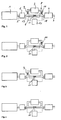
- an engine 1, a starting catalytic converter 2, an adsorber 3 and a main catalytic converter 4 are connected to one another by means of a pipeline system.
- a first pipe part 5 extends between the output of the engine 1 and the input of the starting catalytic converter 2
- a second pipe part 6 extends between the output of the starting catalytic converter 2 and the input of the main catalytic converter 4
- a third pipe part 7 leads away from the main catalytic converter 4 , for example towards an exhaust.
- the adsorber 3 is arranged in a bypass line 8, which opens out from the above-mentioned pipe part 6 on the input side with respect to the adsorber 3, and on the output side with respect to the adsorber 3 again opens into the pipe part 6.
- an exhaust gas flap 9 or 10 to be opened and closed is provided in the bypass line in front of and behind the adsorber 3, and in the pipe part 6, which extends between the starting catalyst 2 and the main catalyst 4, is on at the point which is located between the mouth of the bypass line 8 and the mouth of the bypass line 8, a further exhaust flap 11 to be opened and closed is arranged.
- a sensor 18 is arranged, which detects the temperature of the exhaust gas stream or the gas composition of the exhaust gas stream at least with regard to one of the exhaust gas components HC, CO and NOX or a combination thereof.
- the sensor 18 is acted upon by the exhaust gas flow led through the adsorber 3, the exhaust gas flow emerging from the starting catalytic converter 2 or a mixture thereof.
- the lambda probe 19 is usually arranged downstream of the starting catalytic converter 2; however, it can also be arranged upstream of the starting catalytic converter 2 if the thermal conditions allow it.
- a control unit 20 which receives the signals from the sensor 18 and the lambda probe 19 and determines from this which of the exhaust flaps 9, 10 or 11 is to be opened or closed.
- FIGS. 2 to 4 represent sub-variants of the embodiment according to FIG. 1.
- only the exhaust flaps 10 and 11 are provided
- according to FIG. 3 only the exhaust flaps 9 and 11 are provided
- the minimum solution is according to only the exhaust flap 11 is provided in the embodiment shown in FIG.
- FIG. 5 A further embodiment is shown in FIG. 5, the same components being identified with the same reference numerals as in FIG. 1.
- the bypass line 8 does not branch off from the pipe part 6 extending between the starting catalytic converter 2 and the main catalytic converter 4, as shown in FIG. 1, but already opens out from the pipe section 6 extending between the output of the engine and the input of the starting catalytic converter 2 Pipe part 5 from and in front of the starting catalytic converter 2. Therefore, an exhaust flap to be opened and closed is not arranged in the pipeline part 6, as in FIG. 1, but rather in the pipeline part 5 between the mouth and confluence point of the bypass line 8 with respect to the pipeline part 5.
- This exhaust flap is designated in the drawing with the reference number 12.
- the exhaust flaps 9 and 10 can also optionally be omitted or provided in the exemplary embodiment according to FIG.
- FIG. 6 A further embodiment is shown in FIG. 6, wherein, like in FIGS. 1 and 5, the same elements are designated by the same reference numerals.
- a connecting line 13 is additionally provided in the embodiment according to FIG. 6, which connects the pipe part 5 on the outlet side to the bypass line 8 with respect to the adsorber, and 2 further exhaust flaps 14 and 15 are provided, one of which is an exhaust flap 14 is arranged directly in front of the starting catalytic converter behind the branching point of the branching line 13 in the pipe part 5, and the other exhaust flap 15 in the bypass line 8 is arranged on the output side with respect to the adsorber 3 behind the junction point of the branching line 13 in the bypass line 8.
- the bypass line 8 opens out of the pipe part 5 and into the pipe part 6.
- FIG. 7 A last embodiment is shown in FIG. 7, the same elements as in FIGS. 1, 5 and 6 being designated with the same reference numerals.
- the adsorber is in the bypass line between a connecting line 16, which opens out from the pipe part 6 behind the starting catalytic converter 2 and opens into the bypass line 8 with respect to the adsorber 3 on the inlet side, and that on the outlet side of the adsorber again opening into the pipeline part 6 Bypass line 8 arranged.
- an exhaust flap 17 is arranged in the bypass line 8 in front of the point at which the connecting line 16 opens into the bypass line 8.
- This starting catalytic converter 2 has a central channel which is provided with an exhaust gas flap and is surrounded by a bypass annular gap. When the exhaust flap is closed, the exhaust gas flow flows through the annular gap, whereas when the exhaust flap is open, the flow through the central channel is almost exclusively, since its flow resistance is significantly smaller than that of the annular gap.
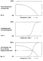
- FIGS. 8 to 10 show the adsorption characteristics of the adsorber and the conversion characteristics of the starting catalyst.
- the adsorber has a high storage rate at the start of operation, i.e. it can store a large volume of pollutants per unit of time. As the time period progresses, the adsorber fills up and also assumes a higher temperature, which reduces the volume that can be stored per unit of time.
- the starting catalytic converter conversion rate at the start of operation is low and only increases relatively steeply after a certain dead time or from a certain temperature.
- the design of the starting catalyst and the adsorber is chosen so that the intersection of the two curves is such that it is as high as possible between 0 and 100%, which means that it is then ensured that the adsorber still guarantees a high adsorber storage volume rate while the exhaust gas volume rate converted by the starting catalytic converter is already relatively high.
- the exhaust flap 11 is initially closed in the exemplary embodiment according to FIG. 1, as a result of which the exhaust gas flow from the engine via the pipeline part 5 through the starting catalytic converter 2 into the bypass line 8 through the adsorber 3 and back again into the pipeline part 6 and finally through the main catalyst 4 and by means of the pipe part 7 flows into the exhaust.
- the exhaust flaps 9 and 10 are closed.
- the exhaust gas flaps 9 and 10 are closed and the exhaust gas flap 11 is opened, after which the main catalytic converter 4 Has the opportunity to heat up to its light-off temperature.
- the exhaust flap 11 is closed again and the exhaust flaps 9 and 10 are opened again, whereby the adsorber 3 is flushed by passing hot exhaust gas through it, which leads to the desorption of the pollutants initially adsorbed in the adsorber.
- These are then passed through the main catalytic converter 4, where the exhaust gas stream, which is additionally enriched with the desorbed exhaust gas components, can be converted in the main catalytic converter 4.
- the exhaust flaps 9 and 10 are closed again, as a result of which the adsorber 3 is completely isolated from the exhaust gas stream; and after later switching off and cooling the engine and the starting catalyst 2 and the main catalyst 4 is ready for a new operation.
- the exhaust flaps 9 and 10 are open at the start of operation and the exhaust flap 12 is closed, as a result of which the entire exhaust gas flow from the engine 1 via the pipeline part 5 by means of the bypass line 8 through the adsorber 3 back into the pipeline part 5 and then through the starting catalyst 2 and by means of the pipeline part 6 through the main catalyst 4 and by means of the pipeline part 7 into the exhaust, and so an adsorption of exhaust gas volume can take place in the adsorber 3.
- the exhaust gas flap 12 is opened and the exhaust gas flaps 9 and 10 are closed, as a result of which the exhaust gas flow directly from the engine 1 by means of the pipe part 5 through the starting catalytic converter 2 and by means of the pipe part 6 through the main catalytic converter 4 and from there is conveyed from the pipe part 7 to the exhaust.
- the exhaust gas flap 12 is closed again and the exhaust gas flaps 9 and 10 become again opened, whereby the adsorber 3 can be rinsed.
- the pollutants desorbed in this way can then react further both in the starting catalytic converter 2 and in the main catalytic converter 4.
- the exhaust flaps 12 and 15 are first closed at the start of operation, and the exhaust flaps 9, 10 and 14 are opened, as a result of which the exhaust gas flow first flows through the adsorber 3, then through the starting catalyst 2 and finally through the main catalyst 4.
- the exhaust gas flap 12 is opened and the exhaust gas flaps 9 and 10 are closed, as a result of which the exhaust gas flow initially flows only from the engine directly through the starting catalytic converter 2 and then through the main catalytic converter 4.
- the exhaust gas flap 12 is closed and the exhaust gas flaps 9 and 10 are opened, as a result of which the exhaust gas components desorbed from the adsorber can be converted both in the starting catalytic converter and in the main catalytic converter.
- the desorbed exhaust gas components can also be converted only in the main catalytic converter by closing the exhaust gas flap 14 and opening the exhaust gas flap 15.
- the exhaust flaps 9, 10, 14 can finally be closed and the exhaust flaps 12 and 14 can be opened, whereby the exhaust gas flow from the engine 1 via the pipeline part 5 through the connecting line 13 through the bypass line 8 and the pipeline part 6 directly into the main catalytic converter 4 and out of it via the pipe part 7 into the exhaust pipe.
- the flaps 8, 9 and 14 can also be closed and the flaps 12 and 15 can be opened, as a result of which the exhaust gas flow then directly from Engine 1 can flow through the main catalyst 4 and from there through the exhaust into the open.
- FIG. 7 A last embodiment is shown in FIG. 7, with exhaust flaps 11 and 17 initially closed and exhaust flaps 14, 9 and 10 open at the start of operation, as a result of which the exhaust gas flow from the engine 1 through the pipe part 5 and subsequently through the starting catalytic converter 2 by means of the connecting line 16 and continues to flow by means of the bypass line 8 through the adsorber 3 back into the pipe part 6 and through the main catalyst 4.
- the exhaust flaps 9 and 10 are closed in addition to the exhaust flap 17 and the exhaust flaps 14 and 11 are opened, so that the exhaust gas flow from the engine 1 is direct can be passed through the starting catalyst 2 and then through the main catalyst 4.
- the exhaust gas flap 11 is closed again and the exhaust gas flaps 9 and 10 are opened, as a result of which the exhaust gas flow can initially flow through the starting catalytic converter 2 via the connecting line 16 through adsorber 3 into the main catalytic converter 4 and the adsorber 3 being rinsed or discharged.
- the exhaust flaps 9 and 10 are closed again and the exhaust flap 11 is opened, and the exhaust gas flow can flow from the engine directly through the starting catalytic converter 2 and then through the main catalytic converter 4.
- the exhaust flap 14 can optionally be closed and the exhaust flap 17 opened, the previously opened exhaust flap 11 remaining in its open state and the previously closed exhaust flaps 9 and 10 in their closed state.
- the exhaust gas flow from the engine 1 can flow through the connecting line 16 by means of the bypass line 8 and directly through the main catalytic converter 4 by means of the pipe part 6, as a result of which the starting catalytic converter is completely switched off during long-distance operation of the vehicle and is thus protected becomes.
- the control of the exhaust flaps 10, 11 will now be explained with reference to the embodiment shown in FIG. 2.
- the exhaust gas flap 11 is closed and the exhaust gas flap 10 is opened, so that the exhaust gas flow is passed completely through the adsorber 3.
- the sensor 18 detects the exhaust gas flow on the outlet side of the adsorber 3. If the probe 18 is suitable for detecting the temperature of the exhaust gas flow, it is determined whether the temperature of the exhaust gas flow exceeds a limit value. This limit value is chosen such that desorption begins in adsorber 3 when the limit value is reached. With this procedure, the knowledge is used that the temperature of the exhaust gas stream after flowing through the adsorber 3 allows conclusions to be drawn about the temperature of the adsorber 3 itself.
- the point at which desorption starts in the adsorber 3 is not solely dependent on the temperature of the adsorber 3, but also on the HC concentration of the exhaust gas stream entering the adsorber 3. Therefore, with the above-described procedure based on temperature detection, the point in time at which the adsorber 3 can no longer be accommodated can only be approximately determined. A significantly more precise determination of this point in time is possible if the sensor 18 determines the gas composition, in particular the HC content, in the exhaust gas stream downstream of the adsorber 3.
- a lambda probe can be used for this purpose, which is surrounded by a catalytically active layer.
- the catalytic layer is chosen so that here a reaction of HC and O 2 takes place.
- the adsorber 3 As long as there is no HC in the exhaust gas stream, ie the adsorber 3 is able to absorb the HC in the exhaust gas stream, the O 2 in the exhaust gas stream can pass the catalytic layer to the actual lambda probe and generate a corresponding signal here.
- Is in the exhaust gas stream downstream of the Adsorbers 3 contain HC, ie the adsorber 3 is saturated, so that HC penetrates through the adsorber 3, react in the catalytic layer HC and O 2 , so that no further O 2 can reach the actual lambda probe and in turn generates a corresponding signal .
- the latter including the catalytic layer, must be heated in a known manner.
- the control unit 20 recognizes from the signal supplied by the sensor 18 that the limit value for the temperature of the exhaust gas flow has been exceeded and / or that HC is contained in the exhaust gas flow, i.e. If the saturation limit of the adsorber 3 has been reached, the control unit 20 closes the exhaust flap 10 and simultaneously opens the exhaust flap 11. With the above-described procedures, it is possible to control the exhaust gas flow exactly as long when the engine 1 is cold started by controlling the exhaust flaps 10, 11 to conduct over the adsorber 3, as it is able to absorb HC.
- the storage capacity of the adsorber is exploited in the best possible way, regardless of the ambient conditions, on the other hand, care is taken to ensure that the exhaust gas flow is no longer sensibly applied to the adsorber 3 and that the exhaust gas flow can be passed directly to the main catalytic converter 4 as early as possible, so that it quickly reaches its activation temperature and ensures effective exhaust gas cleaning.
- the rinsing of the adsorber 3 after reaching the light-off temperature is also controlled with the aid of the sensor 18.
- the sensor 18 is designed as a temperature sensor, the duration of the rinsing process is determined depending on the temperature signal supplied by the sensor 18. For this purpose, values for the rinsing time are stored in a map, not shown, depending on the signal from the sensor. A more precise control is also possible here if the gas composition is determined with the sensor 18. In this case, the exhaust gas flow by controlling the exhaust flaps 10, 11 for so long passed through the adsorber 3 until the sensor 18 in the exhaust gas stream downstream of the adsorber 3 can no longer determine any proportions of HC in the exhaust gas stream.
- the signal of the lambda probe 19, which is arranged upstream of the adsorber 3, is also used. Since the lambda probe 19, if it is arranged behind the starting catalytic converter 2, detects the gas composition directly in front of the adsorber 3, it is now possible to compare the signal from the sensor 18 with the signal from the lambda probe 19. This comparison is particularly easy to carry out if the sensor 18 and the lambda probe 19 are identical parts. In this case, the adsorber 3 is flushed by opening the exhaust flap 10 and closing the exhaust flap 11 until the signals from the sensor 18 and the lambda probe 19 are the same. At this time, the exhaust gas flow flows through the adsorber 3 without a change in the composition of the exhaust gas flow taking place in the adsorber 3 and the adsorber 3 is thus completely desorbed.
- the adsorber 3 i.e. with the exhaust flap 10 closed and the exhaust flap 11 open, the difference between the signals from the sensor 18 and the lambda probe 19 can be formed and stored. The adsorber 3 is then rinsed until the difference in the signals again reaches the previously stored value.
- a characteristic temperature of the engine for example the cooling water or oil temperature, is used to decide whether the adsorber 3 is switched on when the engine 1 starts. If the adsorber 3 is switched on or if it was not completely discharged in a previous operating phase of the engine 1, the adsorber 3 is rinsed according to the procedure outlined above as soon as it is ensured that the main catalyst 4 is its Activation temperature has reached.
- the main catalytic converter 4 reaches its starting temperature significantly faster, so that the total emissions during the starting process are significantly reduced even without the starting catalytic converter 2 are.
- the arrangement of the sensor 18 directly upstream of the main catalytic converter 4 is only absolutely necessary if the control device controls the exhaust gas flaps 9, 10 and 11 with the aid of the previously described comparison of the signals supplied by the sensor 18 and the lambda probe 19. Otherwise, the sensor 18 can also be arranged at any point downstream of the adsorber 3.
- Control of the exhaust flaps 9, 10 and 11 described can be used in the same way for controlling the exhaust flaps 9, 10, 11, 12, 13, 14, 15 and 17 in the embodiments according to FIGS. 1 and 3 to 7, insofar as they are used to apply the exhaust gas flow to the adsorber 3.
Applications Claiming Priority (2)
| Application Number | Priority Date | Filing Date | Title |
|---|---|---|---|
| DE19526765A DE19526765A1 (de) | 1995-07-21 | 1995-07-21 | Verfahren und Vorrichtung zur Abgasreinigung bei Kraftfahrzeugen |
| DE19526765 | 1995-07-21 |
Publications (2)
| Publication Number | Publication Date |
|---|---|
| EP0754841A1 true EP0754841A1 (fr) | 1997-01-22 |
| EP0754841B1 EP0754841B1 (fr) | 2004-04-07 |
Family
ID=7767491
Family Applications (1)
| Application Number | Title | Priority Date | Filing Date |
|---|---|---|---|
| EP96111786A Expired - Lifetime EP0754841B1 (fr) | 1995-07-21 | 1996-07-22 | Procédé et dispositif de purification des gaz d'échappement de véhicules à moteur |
Country Status (3)
| Country | Link |
|---|---|
| EP (1) | EP0754841B1 (fr) |
| JP (1) | JPH0932538A (fr) |
| DE (2) | DE19526765A1 (fr) |
Cited By (6)
| Publication number | Priority date | Publication date | Assignee | Title |
|---|---|---|---|---|
| FR2764637A1 (fr) * | 1997-06-16 | 1998-12-18 | Inst Francais Du Petrole | Procede et ensemble d'elimination des oxydes d'azote presents dans des gaz d'echappement, utilisant un moyen de piegeage des oxydes d'azote |
| EP0972914A2 (fr) * | 1998-07-16 | 2000-01-19 | Honda Giken Kogyo Kabushiki Kaisha | Système de purification des gaz d'échappement pour un moteur à combustion interne |
| EP1013902A2 (fr) * | 1998-12-22 | 2000-06-28 | Toyota Jidosha Kabushiki Kaisha | Dispositif de réglage des émissions d' un moteur à combustion interne et procédé pour sa commande |
| WO2000043648A1 (fr) * | 1999-01-25 | 2000-07-27 | Toyota Jidosha Kabushiki Kaisha | Dispositif de reduction des gaz d'echappement d'un moteur a combustion interne |
| WO2006125928A1 (fr) * | 2005-05-25 | 2006-11-30 | Faurecia Systemes D'echappement | Ligne d'echappement pour moteur thermique |
| US9382829B2 (en) | 2014-10-21 | 2016-07-05 | Toyota Motor Engineering & Manufacturing North America, Inc. | Bypass exhaust pathway to allow gases to bypass the start catalyst of a vehicle |
Families Citing this family (7)
| Publication number | Priority date | Publication date | Assignee | Title |
|---|---|---|---|---|
| DE19837509A1 (de) * | 1998-08-19 | 2000-02-24 | Bayerische Motoren Werke Ag | Abgasanlage einer Brennkraftmaschine mit einem Speichervolumen |
| EP0980966B1 (fr) | 1998-08-19 | 2002-05-08 | Bayerische Motoren Werke Aktiengesellschaft | Système d'échappement avec accumulateur pour un moteur à combustion interne |
| JP3508707B2 (ja) * | 2000-07-31 | 2004-03-22 | トヨタ自動車株式会社 | 車輌用エンジン排気装置 |
| US6922986B2 (en) * | 2001-12-14 | 2005-08-02 | General Motors Corporation | Catalytic converter early light off using cylinder deactivation |
| DE10216537B3 (de) * | 2002-04-15 | 2004-02-05 | Visteon Global Technologies, Inc., Dearborn | Umsteuervorrichtung für strömende Medien, insbesondere Weichenventil für die Abgase einer Verbrennungskraftmaschine |
| JP4174767B2 (ja) * | 2003-10-20 | 2008-11-05 | トヨタ自動車株式会社 | 排ガス浄化装置 |
| US9057303B2 (en) * | 2013-03-14 | 2015-06-16 | Tenneco Automotive Operating Company Inc. | Exhaust system for dual fuel engines |
Citations (8)
| Publication number | Priority date | Publication date | Assignee | Title |
|---|---|---|---|---|
| DE3930380A1 (de) | 1989-09-12 | 1991-03-21 | Porsche Ag | Abgasanlage eines mehrzylinder-verbrennungsmotors |
| US5051244A (en) * | 1990-07-20 | 1991-09-24 | Uop | Use of a molecular sieve bed to minimize emissions during cold start of internal combustion engines |
| FR2686375A1 (fr) * | 1992-01-17 | 1993-07-23 | Ecia Equip Composants Ind Auto | Ligne d'echappement des gaz de sortie d'un moteur notamment de vehicule automobile. |
| EP0588315A1 (fr) * | 1992-09-16 | 1994-03-23 | Nippondenso Co., Ltd. | Dispositif de purification des gaz d'échappement pour moteur à combustion interne |
| US5307627A (en) * | 1993-01-07 | 1994-05-03 | Ford Motor Company | Method and apparatus for oxidizing hydrocarbons from exhaust gases |
| US5315824A (en) * | 1991-08-29 | 1994-05-31 | Toyota Jidosha Kabushiki Kaisha | Cold HC adsorption and removal apparatus for an internal combustion engine |
| JPH0742542A (ja) * | 1993-07-27 | 1995-02-10 | Honda Motor Co Ltd | 内燃機関の排気ガス浄化装置 |
| US5388405A (en) * | 1991-09-30 | 1995-02-14 | Hitachi, Ltd. | System for purifying exhaust gas for use in an automobile |
Family Cites Families (3)
| Publication number | Priority date | Publication date | Assignee | Title |
|---|---|---|---|---|
| KR960004832B1 (ko) * | 1992-08-24 | 1996-04-16 | 미쯔비시지도오샤고오교오 가부시기가이샤 | 배기가스정화장치 |
| JPH0763048A (ja) * | 1993-08-20 | 1995-03-07 | Ngk Insulators Ltd | 排ガス浄化システム及び排ガス浄化方法 |
| DE4400202C1 (de) * | 1994-01-05 | 1995-04-06 | Daimler Benz Ag | Verfahren zur Reduzierung von Kohlenwasserstoff-Emissionen einer Brennkraftmaschine |
-
1995
- 1995-07-21 DE DE19526765A patent/DE19526765A1/de not_active Withdrawn
-
1996
- 1996-07-22 EP EP96111786A patent/EP0754841B1/fr not_active Expired - Lifetime
- 1996-07-22 JP JP8192523A patent/JPH0932538A/ja not_active Withdrawn
- 1996-07-22 DE DE59610966T patent/DE59610966D1/de not_active Expired - Fee Related
Patent Citations (10)
| Publication number | Priority date | Publication date | Assignee | Title |
|---|---|---|---|---|
| DE3930380A1 (de) | 1989-09-12 | 1991-03-21 | Porsche Ag | Abgasanlage eines mehrzylinder-verbrennungsmotors |
| JPH03100313A (ja) | 1989-09-12 | 1991-04-25 | Dr Ing H C F Porsche Ag | 多シリンダ式内燃機関の排ガス装置 |
| US5051244A (en) * | 1990-07-20 | 1991-09-24 | Uop | Use of a molecular sieve bed to minimize emissions during cold start of internal combustion engines |
| US5315824A (en) * | 1991-08-29 | 1994-05-31 | Toyota Jidosha Kabushiki Kaisha | Cold HC adsorption and removal apparatus for an internal combustion engine |
| US5388405A (en) * | 1991-09-30 | 1995-02-14 | Hitachi, Ltd. | System for purifying exhaust gas for use in an automobile |
| FR2686375A1 (fr) * | 1992-01-17 | 1993-07-23 | Ecia Equip Composants Ind Auto | Ligne d'echappement des gaz de sortie d'un moteur notamment de vehicule automobile. |
| EP0588315A1 (fr) * | 1992-09-16 | 1994-03-23 | Nippondenso Co., Ltd. | Dispositif de purification des gaz d'échappement pour moteur à combustion interne |
| US5307627A (en) * | 1993-01-07 | 1994-05-03 | Ford Motor Company | Method and apparatus for oxidizing hydrocarbons from exhaust gases |
| JPH0742542A (ja) * | 1993-07-27 | 1995-02-10 | Honda Motor Co Ltd | 内燃機関の排気ガス浄化装置 |
| US5467594A (en) * | 1993-07-27 | 1995-11-21 | Honda Giken Kogyo Kabushiki Kaisha | Exhaust gas-purifying system for internal combustion engines |
Non-Patent Citations (1)
| Title |
|---|
| PATENT ABSTRACTS OF JAPAN vol. 950, no. 2 * |
Cited By (13)
| Publication number | Priority date | Publication date | Assignee | Title |
|---|---|---|---|---|
| US6018943A (en) * | 1997-06-16 | 2000-02-01 | Institut Francais Du Petrole | Process and assembly for eliminating nitrogen oxides present in exhaust gas, using nitrogen oxides trapping means |
| EP0886042A1 (fr) * | 1997-06-16 | 1998-12-23 | Institut Francais Du Petrole | Procédé et ensemble d'élimination des oxydes d'azote presents dans des gaz d'échappement |
| FR2764637A1 (fr) * | 1997-06-16 | 1998-12-18 | Inst Francais Du Petrole | Procede et ensemble d'elimination des oxydes d'azote presents dans des gaz d'echappement, utilisant un moyen de piegeage des oxydes d'azote |
| EP0972914A3 (fr) * | 1998-07-16 | 2001-08-01 | Honda Giken Kogyo Kabushiki Kaisha | Système de purification des gaz d'échappement pour un moteur à combustion interne |
| EP0972914A2 (fr) * | 1998-07-16 | 2000-01-19 | Honda Giken Kogyo Kabushiki Kaisha | Système de purification des gaz d'échappement pour un moteur à combustion interne |
| US6354076B1 (en) | 1998-07-16 | 2002-03-12 | Honda Giken Kogyo Kabushiki Kaisha | Exhaust gas purification system of internal combustion engine |
| EP1013902A2 (fr) * | 1998-12-22 | 2000-06-28 | Toyota Jidosha Kabushiki Kaisha | Dispositif de réglage des émissions d' un moteur à combustion interne et procédé pour sa commande |
| EP1013902A3 (fr) * | 1998-12-22 | 2003-01-22 | Toyota Jidosha Kabushiki Kaisha | Dispositif de réglage des émissions d' un moteur à combustion interne et procédé pour sa commande |
| WO2000043648A1 (fr) * | 1999-01-25 | 2000-07-27 | Toyota Jidosha Kabushiki Kaisha | Dispositif de reduction des gaz d'echappement d'un moteur a combustion interne |
| US6502391B1 (en) | 1999-01-25 | 2003-01-07 | Toyota Jidosha Kabushiki Kaisha | Exhaust emission control device of internal combustion engine |
| WO2006125928A1 (fr) * | 2005-05-25 | 2006-11-30 | Faurecia Systemes D'echappement | Ligne d'echappement pour moteur thermique |
| FR2886337A1 (fr) * | 2005-05-25 | 2006-12-01 | Faurecia Sys Echappement | Ligne d'echappement pour moteur thermique |
| US9382829B2 (en) | 2014-10-21 | 2016-07-05 | Toyota Motor Engineering & Manufacturing North America, Inc. | Bypass exhaust pathway to allow gases to bypass the start catalyst of a vehicle |
Also Published As
| Publication number | Publication date |
|---|---|
| DE19526765A1 (de) | 1997-01-23 |
| DE59610966D1 (de) | 2004-05-13 |
| EP0754841B1 (fr) | 2004-04-07 |
| JPH0932538A (ja) | 1997-02-04 |
Similar Documents
| Publication | Publication Date | Title |
|---|---|---|
| EP0931922B1 (fr) | Procédé et dispositif d' épuration de gaz d' échappement d'un moteur à combustion interne | |
| EP0913558B1 (fr) | Dispositif d'épuration des gaz d'échappement d'un moteur à combustion interne | |
| DE69813934T2 (de) | Abgasreinigungsverfahren für einen Motor | |
| DE19882303B4 (de) | Vorrichtung, Verfahren und System zur Konzentration und Verringerung adsorbierbarer Schadstoffe | |
| DE69921036T2 (de) | Abgasreinigungsvorrichtung | |
| EP0961876B1 (fr) | Procede pour l'exploitation d'un moteur diesel | |
| DE69829337T2 (de) | Vorrichtung zur Reaktivierung des Katalysators einer Brennkraftmaschine | |
| DE112006001296B4 (de) | Auspufflinie für Brennkraftmotoren | |
| DE10354276A1 (de) | Vorrichtung und Verfahren zur Abgasreinigung für einen Verbrennungsmotor | |
| EP0690210B1 (fr) | Procédé et dispositif de régénération commandée d'un filtre à particules diesel | |
| DE4328125A1 (de) | Abgasreinigungsvorrichtung für einen Verbrennungsmotor oder dergleichen | |
| EP0754841A1 (fr) | Procédé et dispositif de purification des gaz d'échappement de véhicules à moteur | |
| WO2018029230A1 (fr) | Procédé de diagnostic et dispositif pour contrôler le bon fonctionnement d'un composant pour le post-traitement de gaz d'échappement | |
| DE19960430B4 (de) | Abgasreinigungsanlage mit Stickoxid-Speicherkatalysator und Schwefeloxid-Falle und Betriebsverfahren hierfür | |
| DE102017205170B4 (de) | Abgassystem für einen Verbrennungsmotor sowie Verfahren zum Betrieb eines Abgassystems | |
| DE112009000112T5 (de) | Verfahren und Vorrichtung zur Abgasreinigung | |
| EP1387929B1 (fr) | Procede permettant le fonctionnement d'un moteur a combustion interne appartenant notamment a un vehicule automobile | |
| DE10152187A1 (de) | Abgasreinigungsanlage mit Stickoxid-Speicherkatalysator und SCR-Katalysator und Verfahren zur Verminderung des Stickoxidgehalts im Abgas von Brennkraftmaschinen | |
| DE102007030235B4 (de) | Vorrichtung und Verfahren zur Behandlung von Abgasen eines Verbrennungsmotors | |
| DE10318116A1 (de) | Verfahren zum Betreiben einer Brennkraftmaschine insbesondere eines Kraftfahrzeugs | |
| DE19939988A1 (de) | Verfahren zum Betreiben eines Dieselmotors | |
| EP0688940A1 (fr) | Moteur-Otto avec catalyseur | |
| DE19609306A1 (de) | Abgasanlage für eine Brennkraftmaschine | |
| DE19731739C1 (de) | Vorrichtung und Verfahren zur Abgasbehandlung bei einer Brennkraftmaschine | |
| DE19926150B4 (de) | Vorrichtung zum Vermindern von Stickoxiden (NOx) im Abgas einer Brennkraftmaschine, insbesondere einer Diesel-Brennkraftmaschine |
Legal Events
| Date | Code | Title | Description |
|---|---|---|---|
| PUAI | Public reference made under article 153(3) epc to a published international application that has entered the european phase |
Free format text: ORIGINAL CODE: 0009012 |
|
| AK | Designated contracting states |
Kind code of ref document: A1 Designated state(s): DE ES FR GB IT SE |
|
| RAP1 | Party data changed (applicant data changed or rights of an application transferred) |
Owner name: VOLKSWAGEN AKTIENGESELLSCHAFT Owner name: DR.ING. H.C. F. PORSCHE AKTIENGESELLSCHAFT Owner name: BAYERISCHE MOTOREN WERKE AKTIENGESELLSCHAFT Owner name: DAIMLER-BENZ AKTIENGESELLSCHAFT |
|
| 17P | Request for examination filed |
Effective date: 19970721 |
|
| RAP1 | Party data changed (applicant data changed or rights of an application transferred) |
Owner name: VOLKSWAGEN AKTIENGESELLSCHAFT Owner name: DR.ING. H.C. F. PORSCHE AKTIENGESELLSCHAFT Owner name: BAYERISCHE MOTOREN WERKE AKTIENGESELLSCHAFT Owner name: DAIMLERCHRYSLER AG |
|
| 17Q | First examination report despatched |
Effective date: 20000428 |
|
| GRAP | Despatch of communication of intention to grant a patent |
Free format text: ORIGINAL CODE: EPIDOSNIGR1 |
|
| RAP1 | Party data changed (applicant data changed or rights of an application transferred) |
Owner name: VOLKSWAGEN AG Owner name: DR.ING. H.C. F. PORSCHEAKTIENGESELLSCHAFT Owner name: BAYERISCHE MOTOREN WERKE AKTIENGESELLSCHAFT Owner name: DAIMLERCHRYSLER AG |
|
| GRAS | Grant fee paid |
Free format text: ORIGINAL CODE: EPIDOSNIGR3 |
|
| GRAA | (expected) grant |
Free format text: ORIGINAL CODE: 0009210 |
|
| AK | Designated contracting states |
Kind code of ref document: B1 Designated state(s): DE ES FR GB IT SE |
|
| PG25 | Lapsed in a contracting state [announced via postgrant information from national office to epo] |
Ref country code: IT Free format text: LAPSE BECAUSE OF FAILURE TO SUBMIT A TRANSLATION OF THE DESCRIPTION OR TO PAY THE FEE WITHIN THE PRE;WARNING: LAPSES OF ITALIAN PATENTS WITH EFFECTIVE DATE BEFORE 2007 MAY HAVE OCCURRED AT ANY TIME BEFORE 2007. THE CORRECT EFFECTIVE DATE MAY BE DIFFERENT FROM THE ONE RECORDED.SCRIBED TIME-LIMIT Effective date: 20040407 |
|
| REG | Reference to a national code |
Ref country code: GB Ref legal event code: FG4D Free format text: NOT ENGLISH |
|
| REF | Corresponds to: |
Ref document number: 59610966 Country of ref document: DE Date of ref document: 20040513 Kind code of ref document: P |
|
| PG25 | Lapsed in a contracting state [announced via postgrant information from national office to epo] |
Ref country code: SE Free format text: LAPSE BECAUSE OF FAILURE TO SUBMIT A TRANSLATION OF THE DESCRIPTION OR TO PAY THE FEE WITHIN THE PRESCRIBED TIME-LIMIT Effective date: 20040707 |
|
| PG25 | Lapsed in a contracting state [announced via postgrant information from national office to epo] |
Ref country code: ES Free format text: LAPSE BECAUSE OF FAILURE TO SUBMIT A TRANSLATION OF THE DESCRIPTION OR TO PAY THE FEE WITHIN THE PRESCRIBED TIME-LIMIT Effective date: 20040718 |
|
| GBT | Gb: translation of ep patent filed (gb section 77(6)(a)/1977) |
Effective date: 20040720 |
|
| ET | Fr: translation filed | ||
| PLBE | No opposition filed within time limit |
Free format text: ORIGINAL CODE: 0009261 |
|
| STAA | Information on the status of an ep patent application or granted ep patent |
Free format text: STATUS: NO OPPOSITION FILED WITHIN TIME LIMIT |
|
| 26N | No opposition filed |
Effective date: 20050110 |
|
| PGFP | Annual fee paid to national office [announced via postgrant information from national office to epo] |
Ref country code: DE Payment date: 20090127 Year of fee payment: 13 |
|
| PGFP | Annual fee paid to national office [announced via postgrant information from national office to epo] |
Ref country code: GB Payment date: 20090126 Year of fee payment: 13 |
|
| REG | Reference to a national code |
Ref country code: FR Ref legal event code: TQ |
|
| PGFP | Annual fee paid to national office [announced via postgrant information from national office to epo] |
Ref country code: FR Payment date: 20090129 Year of fee payment: 13 |
|
| REG | Reference to a national code |
Ref country code: FR Ref legal event code: CD |
|
| GBPC | Gb: european patent ceased through non-payment of renewal fee |
Effective date: 20090722 |
|
| REG | Reference to a national code |
Ref country code: FR Ref legal event code: ST Effective date: 20100331 |
|
| PG25 | Lapsed in a contracting state [announced via postgrant information from national office to epo] |
Ref country code: FR Free format text: LAPSE BECAUSE OF NON-PAYMENT OF DUE FEES Effective date: 20090731 |
|
| PG25 | Lapsed in a contracting state [announced via postgrant information from national office to epo] |
Ref country code: GB Free format text: LAPSE BECAUSE OF NON-PAYMENT OF DUE FEES Effective date: 20090722 |
|
| PG25 | Lapsed in a contracting state [announced via postgrant information from national office to epo] |
Ref country code: DE Free format text: LAPSE BECAUSE OF NON-PAYMENT OF DUE FEES Effective date: 20100202 |