EP0980966B1 - Système d'échappement avec accumulateur pour un moteur à combustion interne - Google Patents
Système d'échappement avec accumulateur pour un moteur à combustion interne Download PDFInfo
- Publication number
- EP0980966B1 EP0980966B1 EP99115344A EP99115344A EP0980966B1 EP 0980966 B1 EP0980966 B1 EP 0980966B1 EP 99115344 A EP99115344 A EP 99115344A EP 99115344 A EP99115344 A EP 99115344A EP 0980966 B1 EP0980966 B1 EP 0980966B1
- Authority
- EP
- European Patent Office
- Prior art keywords
- exhaust
- engine
- exhaust gas
- storage volume
- internal combustion
- Prior art date
- Legal status (The legal status is an assumption and is not a legal conclusion. Google has not performed a legal analysis and makes no representation as to the accuracy of the status listed.)
- Expired - Lifetime
Links
Images
Classifications
-
- F—MECHANICAL ENGINEERING; LIGHTING; HEATING; WEAPONS; BLASTING
- F02—COMBUSTION ENGINES; HOT-GAS OR COMBUSTION-PRODUCT ENGINE PLANTS
- F02D—CONTROLLING COMBUSTION ENGINES
- F02D9/00—Controlling engines by throttling air or fuel-and-air induction conduits or exhaust conduits
- F02D9/04—Controlling engines by throttling air or fuel-and-air induction conduits or exhaust conduits concerning exhaust conduits
-
- F—MECHANICAL ENGINEERING; LIGHTING; HEATING; WEAPONS; BLASTING
- F01—MACHINES OR ENGINES IN GENERAL; ENGINE PLANTS IN GENERAL; STEAM ENGINES
- F01N—GAS-FLOW SILENCERS OR EXHAUST APPARATUS FOR MACHINES OR ENGINES IN GENERAL; GAS-FLOW SILENCERS OR EXHAUST APPARATUS FOR INTERNAL COMBUSTION ENGINES
- F01N3/00—Exhaust or silencing apparatus having means for purifying, rendering innocuous, or otherwise treating exhaust
- F01N3/08—Exhaust or silencing apparatus having means for purifying, rendering innocuous, or otherwise treating exhaust for rendering innocuous
- F01N3/10—Exhaust or silencing apparatus having means for purifying, rendering innocuous, or otherwise treating exhaust for rendering innocuous by thermal or catalytic conversion of noxious components of exhaust
- F01N3/18—Exhaust or silencing apparatus having means for purifying, rendering innocuous, or otherwise treating exhaust for rendering innocuous by thermal or catalytic conversion of noxious components of exhaust characterised by methods of operation; Control
- F01N3/20—Exhaust or silencing apparatus having means for purifying, rendering innocuous, or otherwise treating exhaust for rendering innocuous by thermal or catalytic conversion of noxious components of exhaust characterised by methods of operation; Control specially adapted for catalytic conversion ; Methods of operation or control of catalytic converters
-
- F—MECHANICAL ENGINEERING; LIGHTING; HEATING; WEAPONS; BLASTING
- F02—COMBUSTION ENGINES; HOT-GAS OR COMBUSTION-PRODUCT ENGINE PLANTS
- F02M—SUPPLYING COMBUSTION ENGINES IN GENERAL WITH COMBUSTIBLE MIXTURES OR CONSTITUENTS THEREOF
- F02M26/00—Engine-pertinent apparatus for adding exhaust gases to combustion-air, main fuel or fuel-air mixture, e.g. by exhaust gas recirculation [EGR] systems
- F02M26/13—Arrangement or layout of EGR passages, e.g. in relation to specific engine parts or for incorporation of accessories
- F02M26/14—Arrangement or layout of EGR passages, e.g. in relation to specific engine parts or for incorporation of accessories in relation to the exhaust system
- F02M26/15—Arrangement or layout of EGR passages, e.g. in relation to specific engine parts or for incorporation of accessories in relation to the exhaust system in relation to engine exhaust purifying apparatus
-
- F—MECHANICAL ENGINEERING; LIGHTING; HEATING; WEAPONS; BLASTING
- F02—COMBUSTION ENGINES; HOT-GAS OR COMBUSTION-PRODUCT ENGINE PLANTS
- F02M—SUPPLYING COMBUSTION ENGINES IN GENERAL WITH COMBUSTIBLE MIXTURES OR CONSTITUENTS THEREOF
- F02M26/00—Engine-pertinent apparatus for adding exhaust gases to combustion-air, main fuel or fuel-air mixture, e.g. by exhaust gas recirculation [EGR] systems
- F02M26/13—Arrangement or layout of EGR passages, e.g. in relation to specific engine parts or for incorporation of accessories
- F02M26/34—Arrangement or layout of EGR passages, e.g. in relation to specific engine parts or for incorporation of accessories with compressors, turbines or the like in the recirculation passage
-
- F—MECHANICAL ENGINEERING; LIGHTING; HEATING; WEAPONS; BLASTING
- F02—COMBUSTION ENGINES; HOT-GAS OR COMBUSTION-PRODUCT ENGINE PLANTS
- F02M—SUPPLYING COMBUSTION ENGINES IN GENERAL WITH COMBUSTIBLE MIXTURES OR CONSTITUENTS THEREOF
- F02M26/00—Engine-pertinent apparatus for adding exhaust gases to combustion-air, main fuel or fuel-air mixture, e.g. by exhaust gas recirculation [EGR] systems
- F02M26/13—Arrangement or layout of EGR passages, e.g. in relation to specific engine parts or for incorporation of accessories
- F02M26/37—Arrangement or layout of EGR passages, e.g. in relation to specific engine parts or for incorporation of accessories with temporary storage of recirculated exhaust gas
-
- F—MECHANICAL ENGINEERING; LIGHTING; HEATING; WEAPONS; BLASTING
- F02—COMBUSTION ENGINES; HOT-GAS OR COMBUSTION-PRODUCT ENGINE PLANTS
- F02M—SUPPLYING COMBUSTION ENGINES IN GENERAL WITH COMBUSTIBLE MIXTURES OR CONSTITUENTS THEREOF
- F02M26/00—Engine-pertinent apparatus for adding exhaust gases to combustion-air, main fuel or fuel-air mixture, e.g. by exhaust gas recirculation [EGR] systems
- F02M26/65—Constructional details of EGR valves
- F02M26/71—Multi-way valves
-
- F—MECHANICAL ENGINEERING; LIGHTING; HEATING; WEAPONS; BLASTING
- F01—MACHINES OR ENGINES IN GENERAL; ENGINE PLANTS IN GENERAL; STEAM ENGINES
- F01N—GAS-FLOW SILENCERS OR EXHAUST APPARATUS FOR MACHINES OR ENGINES IN GENERAL; GAS-FLOW SILENCERS OR EXHAUST APPARATUS FOR INTERNAL COMBUSTION ENGINES
- F01N2240/00—Combination or association of two or more different exhaust treating devices, or of at least one such device with an auxiliary device, not covered by indexing codes F01N2230/00 or F01N2250/00, one of the devices being
- F01N2240/26—Combination or association of two or more different exhaust treating devices, or of at least one such device with an auxiliary device, not covered by indexing codes F01N2230/00 or F01N2250/00, one of the devices being an exhaust gas reservoir, e.g. emission buffer
-
- F—MECHANICAL ENGINEERING; LIGHTING; HEATING; WEAPONS; BLASTING
- F02—COMBUSTION ENGINES; HOT-GAS OR COMBUSTION-PRODUCT ENGINE PLANTS
- F02M—SUPPLYING COMBUSTION ENGINES IN GENERAL WITH COMBUSTIBLE MIXTURES OR CONSTITUENTS THEREOF
- F02M26/00—Engine-pertinent apparatus for adding exhaust gases to combustion-air, main fuel or fuel-air mixture, e.g. by exhaust gas recirculation [EGR] systems
- F02M26/13—Arrangement or layout of EGR passages, e.g. in relation to specific engine parts or for incorporation of accessories
- F02M26/42—Arrangement or layout of EGR passages, e.g. in relation to specific engine parts or for incorporation of accessories having two or more EGR passages; EGR systems specially adapted for engines having two or more cylinders
Definitions
- the invention relates to an exhaust system of an internal combustion engine with a storage volume, according to the features in the preamble of claim 1.
- DE 40 25 becomes the known prior art 565 A1 to GB 1 349 051 and in particular to US 3,645,098, of which this Registration runs out, referenced.
- the storage volume is similar to that of a bellows (that of a pump) sucked empty and kept empty by a check valve at the outlet can be.
- a flap closes behind the exhaust gas purification device that the exhaust gas into the overhead pipe, such that the exhaust gas through a further line into the storage volume is led, which is inflated by the exhaust gas.
- the disadvantage of this solution is the uncontrolled inflation of the storage volume with exhaust gas.
- the degree of filling of the storage volume has different pressure ratios in the exhaust system that influence the charge change of the internal combustion engine. This is particularly disadvantageous after a start (restart) of the internal combustion engine, because the mixture formation processes are negatively influenced, resulting in a very restless Internal combustion engine run can result.
- the object of the present invention is after the start of the internal combustion engine Defined pressure ratios in the exhaust line during filling of the storage volume to have with exhaust gas. This task is characterized by the feature in characterizing part of claim 1 solved.
- a control valve for metered filling of the Storage volume may be provided, which then follows a start the internal combustion engine with the associated desired Filling the storage volume the negative pressure initially present therein not abruptly, but quasi-dosed degradation. This is a suction of internal combustion engine exhaust gas from the internal combustion engine exhaust pipe possible over a longer period. Preference is given to the best possible Implementation of this method in addition to a pressure value in the Storage volume-sensing pressure sensor a the vacuum pump and / or suitably controlling the control valve based on the pressure sensor signals Control unit provided.
- a suitable adsorber material can be stored in the storage volume an undesirable exhaust gas component may be provided, so that in the Storage volume introduced exhaust gases at least partially cleaned at the same time before they expire after the desired or required storage period back into the exhaust pipe of the internal combustion engine be delivered.
- the exhaust system partially double-walled, so that two essentially Exhaust gas lines running coaxially to one another are present, wherein Via the first, preferably inner exhaust pipe, the exhaust gas from the internal combustion engine led away and via the second, preferably outer exhaust pipe is led to the storage volume.
- an exhaust system according to the invention is that the partially double-walled exhaust system itself is part of the Storage volume forms, with a minimal additional space requirement, so that the actual storage volume is made smaller accordingly can be.
- Exhaust system is a relatively simple exhaust system for close to the internal combustion engine arranged storage volume possible.
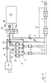
- Reference number 1 thus designates an (here four-cylinder reciprocating piston) internal combustion engine, the exhaust gases of which are first passed via exhaust manifolds 2 into (here two parallel side by side) electrically heatable pre-catalysts 3.
- exhaust pipes 4 referred to as first exhaust pipe in FIG. 2
- exhaust pipes 4 ′ FIG. 1
- the internal combustion engine exhaust gases then enter a main catalytic converter 5 and from there through an exhaust pipe 4, which has at least one silencer 19, finally into the Surroundings.
- a shutoff flap 6 is provided in the exhaust line 4 downstream of the sound damper 19, by means of which the exhaust line 4 can be shut off essentially completely, ie when the shutoff flap 6 is closed, the exhaust gas flow flowing through the muffler 19 cannot get into the environment.
- the exhaust gas flow conducted in the exhaust gas line 4 ′ is conducted via a branch line 7 branching off upstream of the main catalytic converter 5 into a storage volume 8.
- the exhaust gas flow with the shut-off flap 6 closed can also be taken downstream of the main catalytic converter 5 or - as shown here via the branch line 7 ′ shown in dashed lines - downstream of the silencer 19 from the exhaust line 4 and fed to the storage volume 8.
- both a control valve 9 provided in the branch line 7 and a further shut-off valve 10a designed as a three-way valve 10 must be suitably connected for this purpose, ie these two valves 9, 10a, the function of which will be discussed in more detail later, must flow through the exhaust gas release the branch line 7 at least partially.
- the introduction of the exhaust gas flow just described is intended in the storage volume 8 especially after a (cold) start of the Internal combustion engine 1, so if the pre-catalysts 3 and the main catalyst 5 have not yet reached their light-off temperature and thus are unable to remove harmful exhaust gas components (especially hydrocarbons) to convert for a certain period of time (e.g. 25 Seconds).
- a certain period of time e.g. 25 Seconds.
- the locking flap 6 is opened so that then the exhaust gas stream is cleaned, i.e. of at least the essential ones Free pollutant components, is discharged into the environment.
- the storage volume can 8 to be emptied for a later (new) start or cold start the internal combustion engine 1 to be able to again during the said Time span of, for example, 25 seconds of exhaust gas flow take.
- This required emptying of the storage volume 8 can either in the suction system 11 of the internal combustion engine 1 or in the exhaust pipe 4 'into it.
- One of the storage volume is provided for this 8 branching drain line 17, which is in a branch valve 20th in a first line branch 17 'opening into the suction system 11 and in branches a second line branch 17 ′′ opening into the exhaust gas line 4 ′.
- the amount of exhaust gas stored in the storage volume 8 is either for "cleaning" (or aftertreatment) by the then functional Main catalyst 5 out, or alternatively in the intake system 11 of the internal combustion engine 1 initiated.
- the previously in the storage volume 8 stored amount of exhaust gas thus when this storage volume is emptied 8 suitable for repeated post-combustion fed to the internal combustion engine combustion chambers for combustion Fresh gas stream added, preferably at such operating points the internal combustion engine 1, in which this admixture for a flawless Run of the internal combustion engine 1 is not a hindrance.
- the other elements shown in FIG. 1 in the periphery of the internal combustion engine 1 are briefly explained:
- the (here four) combustion chambers of the internal combustion engine 1 are supplied with fresh gas via the intake system 11 already mentioned.
- a throttle valve 13 is provided in an intake line 12 leading to the intake system 11 for controlling the power of the internal combustion engine 1.
- a conventional intake air filter 14 At the free end of the intake line 12 there is a conventional intake air filter 14.
- a secondary air line 15 which opens into the exhaust manifold 2 and is known to the person skilled in the art, branches off, in which, as usual, a secondary air pump 16 is provided, but for the present invention is immaterial.
- a vacuum pump 18 can be seen in this in addition to a shut-off valve 10b, which in turn is part of the three-way valve 10 already mentioned or forms this three-way valve 10 together with the other already mentioned shut-off valve 10a If the shut-off valve 10a is now closed and the shut-off valve 10b is open, ie if the three-way valve 10 assumes the switch position shown in FIG. 1 , the storage volume 8 is sucked empty and thus evacuated when this vacuum pump 18 is operated at the same time, since this vacuum pump 18 adopts with its suction side the storage volume 8 is connected. As already mentioned, the vacuum pump 18 then conveys the amount of exhaust gas located in the storage volume 8 via the emptying line 17 either into the suction system 11 or into the exhaust line 4 '.
- a feed pump (already shown in the prior art mentioned at the outset) can additionally be provided, which enables the accumulation of exhaust gas amount to be stored in the storage volume 8 under excess pressure, as a result of which this storage volume 8 can be dimensioned smaller.
- a feed pump is usually shown in FIG. 2 , which will be explained later, under reference number 24.
- a less powerful feed pump (24) can now be used, or - as in DE 43 42 296 C1, which has also already been mentioned - the internal combustion engine 1 can be adapted by adapting its valve timing to compress the exhaust gas are used after an absolutely safe introduction of the exhaust gas flow into the storage volume 8 is ensured by the vacuum prevailing initially (ie when the internal combustion engine 1 is started) in the storage volume 8.
- An electronic control unit in particular, is not shown in the figure, among others the shut-off flap 6 and the three-way valve 10, i.e. the check valves 10a and 10b positioned according to the respective requirements.
- This Control unit can also - preferably using the signals of a in particular provided in the storage volume 8 and the respective current one
- the pressure sensor detecting the pressure value here - the appropriate control the control valve 9 and the vacuum pump 18.
- this control unit (possibly using further signals or boundary conditions) by suitable control of the control valve 9 in the mouth area the branch line 7 or 7 "into the exhaust line 4 'or 4 one set an approximately constant vacuum of, for example, 0.75 bar.
- this control unit can ensure that this emptying and the associated admixture the amount of exhaust gas collected in the storage volume 8 for the internal combustion engine combustion chambers fresh gas flow supplied only in those operating points the internal combustion engine 1 takes place in which this admixture is not a hindrance to the smooth running of the internal combustion engine. Furthermore, in the subsequent build-up of the negative pressure in the storage volume 8 said control unit operates the vacuum pump Monitor 18 such that the desired negative pressure in the storage volume 8 is generated in the desired order.
- the conveying side should be connected to the environment be, for example.
- the drain line 17 and the exhaust pipe 4.
- the delivery side of the vacuum pump 18 with the suction system 11 Internal combustion engine 1 is connectable, requires a reduced pump output if, in addition - as is known to the person skilled in the art - in the Suction system 11 at a variety of engine operating points (and particularly intensively at idle) prevailing negative pressure becomes.
- the control unit already mentioned can be the vacuum pump 18 operate appropriately.
- the detailed structure of the storage volume 8 is not to be discussed in detail. In essence, this can be a suitable vacuum storage that is stable when the evacuation is complete.
- an absolute tightness is required not only of the vacuum accumulator or the accumulator volume 8, but also of the check valves 10a, 10b (or the three-way valve 10) as well as the drain line 17 and the branch line 7.
- an adsorber material can also be provided in the storage volume 8, which itself stores at least one undesired exhaust gas component for a certain period of time or, as known to the person skilled in the art, for example, as activated carbon, has an adsorbent effect on pollutants.
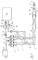
- FIG. 2 and the essential differences of this second exemplary embodiment compared to that according to FIG. 1 are now described: While in normal continuous engine operation the internal combustion engine exhaust gases ultimately reach the environment through the so-called first exhaust pipe 4, as shown by the flow arrow, via the main catalytic converter 5 and via the muffler 19, the internal combustion engine will also start during this 1 subsequent "critical" period, during which neither the pre-catalytic converters 3 nor the main catalytic converter 5 have reached their starting or operating temperature, the shut-off flap 6 provided downstream of the muffler 19 in the exhaust pipe 4 is closed, so that the first exhaust pipe 4 is connected to it Is essentially completely closed off. When the shut-off flap 6 is closed, the exhaust gas flow flowing through the muffler 19 cannot get into the environment, but is directed into a storage volume 8. In the exemplary embodiment according to FIG. 2, this takes place in the following way:
- a transition 21 is provided in the first exhaust line 4 into a second exhaust line 22, into which the exhaust gas flow - as shown by flow arrows - enters with the shut-off valve 6 closed.
- This second exhaust line 22 is arranged coaxially or concentrically to the first exhaust line 4 or envelops the first exhaust line 4, an annular space (not specified in more detail) being present between the outer wall of the first exhaust line 4 and the inner wall of the second exhaust line 22, through which the internal combustion engine exhaust gases then be guided in the second exhaust line 22.
- This second exhaust line 22 extends from the transfer line 21 in the direction of the internal combustion engine 1 (back) to a so-called diversion 23, which is upstream of the pre-catalytic converter 3 on the left-hand side with respect to the flow direction in the second exhaust-gas line 22, and for the pre-catalytic converter on the right-hand side 3 is provided between this pre-catalyst 3 and the internal combustion engine 1.
- the internal combustion engine exhaust system shown is thus double-walled, with not only the exhaust line 4 but also the exhaust gas purification devices in the form of the main catalytic converter 5 and the pre-catalytic converter 3 on the right being encased by the exhaust gas line 22.
- coaxially enveloping second exhaust line 22 now closes the in Connection with the first exemplary embodiment already explained branch line 7, which ultimately also in the storage volume 8, which has also already been explained empties.
- branch line 7 which ultimately also in the storage volume 8
- the shut-off flap 6 is closed, the internal combustion engine exhaust gases via the second exhaust line 22 and the adjoining one Branch line 7 introduced into the storage volume 8.
- the one provided in the branch line 7 as a three-way valve 10 formed check valve 10a can be switched suitably, i.e. this Check valve 10a must allow the flow of exhaust gas flow through the branch line 7 release.
- the introduction of the exhaust gas flow just described is intended in the storage volume 8 especially after a (cold) start the internal combustion engine 1, so if the pre-catalysts 3 and the main catalyst 5 have not yet reached their light-off temperature and thus are unable to remove harmful exhaust gas components (especially hydrocarbons) to convert for a certain period of time (e.g. 25 Seconds).
- a certain period of time e.g. 25 Seconds.
- the locking flap 6 is opened so that then the exhaust gas stream is cleaned, i.e. of at least the essential ones Free pollutant components, is discharged into the environment.
- the storage volume can 8 to be emptied for a later (new) start or cold start the internal combustion engine 1 to be able to again during the said Time span of, for example, 25 seconds of exhaust gas flow take.
- This required emptying of the storage volume 8 takes place in this second exemplary embodiment, only in the suction system 11 the internal combustion engine 1, namely via the drain line 17, wherein a targeted quantity control of those taken from the storage volume 8 and the suction system 11 fed and thus recirculated exhaust gas amount by means of a control valve provided in the drain line 17 25 takes place.
- the vacuum pump 18 In the emptying line 17 there is also the vacuum pump 18 already explained in connection with the exemplary embodiment according to FIG. 1.
- the pre-catalysts 3 generally an exhaust gas cleaning device
- the amount of exhaust gas previously collected in the storage volume 8 was removed from the storage volume 8 - an essentially absolute vacuum was created with this vacuum pump 18 in the storage volume 8.
- the exhaust system is partially double-walled is, so that the engine exhaust gas in this area in one first exhaust pipe 4, which contains the exhaust gas purification device (s), led away from the internal combustion engine 1 and coaxially in a second this first extending exhaust pipe 22 in the manner of a counterflow heat exchanger returned in the direction of the internal combustion engine 1, ultimately, however, is introduced into the storage volume 8.
- the first exhaust pipe 4 is the inner one and the second one Exhaust line 22 around the outer exhaust line of the double-walled, an exhaust system having an annular space. Rather can also the first exhaust line 4 on the outside and the second exhaust line 22 be provided on the inside, the latter then the exhaust gas purification devices, i.e. the main catalytic converter 5 and the precatalyst (s) 3 would penetrate.
Claims (9)
- Installation d'échappement de moteur à combustion interne comportant un dispositif de nettoyage des gaz d'échappement (3, 5) ainsi qu'un volume accumulateur (8) qui peut être évacué dans lequel on recueille au moins une partie des gaz d'échappement du moteur produits après le démarrage du moteur à combustion interne (1) pendant une certaine durée, et dont l'orifice de sortie est fermé par une vanne d'arrêt (10, 10a, 10b),
caractérisée par
une pompe à dépression (18) créant une dépression dans le volume accumulateur (8), cette dépression étant maintenue à l'arrêt du moteur à combustion interne (1) par la vanne d'arrêt (10, 10a, 10b). - Installation d'échappement de moteur à combustion interne selon la revendication 1,
caractérisée en ce que
la pompe à dépression (18) reliée par son côté aspiration au volume accumulateur (8) est reliée par son côté de refoulement au collecteur d'admission (11) du moteur à combustion interne (1) et/ou à la conduite d'échappement (4') en amont du dispositif de nettoyage des gaz d'échappement (catalyseur principal 5). - Installation d'échappement selon la revendication 1 ou 2,
caractérisée en ce qu'
à côté d'un volet d'arrêt (6) prévu dans l'installation d'échappement en aval du dispositif de nettoyage des gaz d'échappement (5), la conduite de dérivation (7) conduisant la veine de gaz d'échappement du moteur vers le volume accumulateur (8) comporte une vanne de régulation (9) pour le remplissage dosé du volume accumulateur (8). - Installation d'échappement selon l'une quelconque des revendications précédentes,
caractérisée par
un capteur de pression détectant la pression dans le volume accumulateur (8) et une unité de commande pour commander la pompe à dépression (18) et/ou la vanne de régulation (9) à l'aide de signaux du capteur de pression. - Installation d'échappement selon l'une quelconque des revendications précédentes,
caractérisée en ce que
le volume accumulateur (8) contient au moins une matière adsorbante pour fixer des composants polluants des gaz d'échappement. - Installation d'échappement selon l'une quelconque des revendications précédentes,
caractérisée en ce que
l'installation d'échappement est réalisée en partie à double paroi pour constituer deux conduites d'échappement (4, 22) essentiellement coaxiales, la première notamment la conduite d'échappement intérieure (4) évacuant les gaz d'échappement du moteur à combustion interne (1) et la seconde, de préférence la conduite d'échappement extérieure (22) aboutissant au volume accumulateur (8). - Installation d'échappement selon la revendication 6,
caractérisée en ce qu'
en amont d'une première conduite de gaz d'échappement (4) notamment la conduite intérieure, en aval du dispositif de nettoyage (5) des gaz d'échappement, il est prévu un volet d'arrêt (6) et en amont de celui-ci, une déviation (21) pour la seconde conduite de gaz d'échappement (22) de préférence la conduite extérieure. - Installation d'échappement selon les revendications 6 ou 7,
caractérisée en ce que
le segment compris entre le moteur à combustion interne (1) et un dispositif de nettoyage des gaz d'échappement en forme de précatalyseurs (3), comporte une conduite de sortie (23) de la seconde conduite d'échappement (22) de préférence la conduite extérieure, reliée à la conduite de dérivation (17) rejoignant le volume accumulateur (8). - Installation d'échappement selon l'une quelconque des revendications précédentes,
caractérisée en ce que
la conduite de dérivation (17) conduisant les gaz d'échappement du moteur à combustion interne dans le volume accumulateur (8) comporte une pompe de refoulement (24).
Applications Claiming Priority (4)
| Application Number | Priority Date | Filing Date | Title |
|---|---|---|---|
| DE19837509A DE19837509A1 (de) | 1998-08-19 | 1998-08-19 | Abgasanlage einer Brennkraftmaschine mit einem Speichervolumen |
| DE19837507 | 1998-08-19 | ||
| DE19837507A DE19837507A1 (de) | 1998-08-19 | 1998-08-19 | Abgasanlage einer Brennkraftmaschine mit einem Speichervolumen |
| DE19837509 | 1998-08-19 |
Publications (2)
| Publication Number | Publication Date |
|---|---|
| EP0980966A1 EP0980966A1 (fr) | 2000-02-23 |
| EP0980966B1 true EP0980966B1 (fr) | 2002-05-08 |
Family
ID=26048248
Family Applications (1)
| Application Number | Title | Priority Date | Filing Date |
|---|---|---|---|
| EP99115344A Expired - Lifetime EP0980966B1 (fr) | 1998-08-19 | 1999-08-03 | Système d'échappement avec accumulateur pour un moteur à combustion interne |
Country Status (3)
| Country | Link |
|---|---|
| US (1) | US6250073B1 (fr) |
| EP (1) | EP0980966B1 (fr) |
| DE (1) | DE59901383D1 (fr) |
Families Citing this family (30)
| Publication number | Priority date | Publication date | Assignee | Title |
|---|---|---|---|---|
| DE59811106D1 (de) * | 1998-02-25 | 2004-05-06 | Alstom Technology Ltd Baden | Kraftwerksanlage und Verfahren zum Betrieb einer Kraftwerksanlage mit einem CO2-Prozess |
| EP1238187B1 (fr) * | 1999-12-08 | 2005-03-16 | Volkswagen Aktiengesellschaft | Dispositif d'amenee des gaz d'echappement d'un moteur a combustion interne a un catalyseur, notamment un catalyseur a accumulation |
| DE10202171A1 (de) * | 2002-01-22 | 2003-07-31 | Bayerische Motoren Werke Ag | Kraftfahrzeug mit einem Kryotank |
| JP3912192B2 (ja) * | 2002-06-05 | 2007-05-09 | トヨタ自動車株式会社 | 内燃機関の排気浄化方法、及び排気浄化装置並びに排気捕集装置 |
| US20040226289A1 (en) * | 2003-01-18 | 2004-11-18 | Hagerty Jon C. | Exhaust containment system |
| DE10309468A1 (de) * | 2003-03-03 | 2004-09-23 | Dr.Ing.H.C. F. Porsche Ag | Abgasleitung einer Brennkraftmaschine mit steuerbaren Abgasklappen |
| FR2857697B1 (fr) * | 2003-07-15 | 2006-01-21 | Inst Francais Du Petrole | Moteur a combustion interne a quatre temps suralimente avec dispositif d'echappement des gaz d'echappement a volume variable et procede de fonctionnement d'un tel moteur |
| FR2873405B1 (fr) * | 2004-07-21 | 2009-08-07 | Renault V I Sa | Dispositif et procede de suralimentation en gaz comprime d'une tubulure d'admission d'un moteur turbo-compresse |
| FR2880073B1 (fr) * | 2004-12-23 | 2007-03-30 | Renault Sas | Dispositif de recyclage des gaz d'echappement d'un moteur a combustion interne |
| US7357125B2 (en) * | 2005-10-26 | 2008-04-15 | Honeywell International Inc. | Exhaust gas recirculation system |
| AT503458B1 (de) * | 2006-04-03 | 2008-09-15 | Man Nutzfahrzeuge Oesterreich | Abgasanlage einer antriebseinheit für ein kraftfahrzeug mit abgasrückführung |
| FR2902151B1 (fr) * | 2006-06-07 | 2008-08-08 | Peugeot Citroen Automobiles Sa | Moteur a combustion interne ayant un circuit de recirculation des gaz d'echappement |
| US8069655B2 (en) * | 2007-08-13 | 2011-12-06 | Cummins Filtration Ip, Inc. | Apparatus, system, and method for using a fraction of engine exhaust to deliver a dosant |
| US8652007B2 (en) * | 2008-12-11 | 2014-02-18 | Toyota Jidosha Kabushiki Kaisha | Pressure accumulation system for internal combustion engine |
| GB0912081D0 (en) * | 2009-07-11 | 2009-08-19 | Tonery David | Combustion method and apparatus |
| US8516797B2 (en) * | 2009-09-29 | 2013-08-27 | Ford Global Technologies, Llc | Control of exhaust flow in an engine including a particulate filter |
| JP5516759B2 (ja) * | 2011-02-10 | 2014-06-11 | トヨタ自動車株式会社 | 排気還流装置 |
| US9279396B2 (en) * | 2012-05-17 | 2016-03-08 | Ford Global Technologies, Llc | Boost air management for improved engine performance |
| EP2667006A1 (fr) * | 2012-05-25 | 2013-11-27 | Turner Powertrain Systems Limited | Système de suralimentation de moteur |
| US9541039B2 (en) * | 2013-03-14 | 2017-01-10 | Cummins Ip, Inc. | Apparatus, system, and method for reducing emission of nitrogen oxides |
| US20140278017A1 (en) * | 2013-03-14 | 2014-09-18 | Cummins Ip, Inc. | Apparatus, system, and method for reducing engine knock |
| EP3247890B1 (fr) * | 2015-01-21 | 2019-06-12 | Telefonaktiebolaget LM Ericsson (publ) | Procédé et système de traitement de pollution pour véhicules |
| CN105484838A (zh) * | 2016-01-18 | 2016-04-13 | 奇瑞汽车股份有限公司 | 汽车冷启动废气处理装置及处理方法 |
| US10690072B2 (en) * | 2016-10-19 | 2020-06-23 | Ford Global Technologies, Llc | Method and system for catalytic conversion |
| IT201700055359A1 (it) * | 2017-05-22 | 2018-11-22 | Fpt Motorenforschung Ag | Configurazione egr di un motore a combustione interna comprendente un ats |
| DE102018215877A1 (de) * | 2018-09-18 | 2020-03-19 | Bayerische Motoren Werke Aktiengesellschaft | Abgaseinrichtung für eine Verbrennungskraftmaschine eines Kraftfahrzeugs und Kraftfahrzeug mit einer solchen Abgaseinrichtung |
| FR3085998B1 (fr) * | 2018-09-18 | 2020-09-11 | Psa Automobiles Sa | Ligne d’echappement de vehicule a circuit de refroidissement par gaz neutre en amont du dispositif de depollution |
| DE102019202383A1 (de) * | 2019-02-21 | 2019-11-28 | Audi Ag | Verfahren zum Betreiben einer Antriebseinrichtung für ein Kraftfahrzeug sowie entsprechende Antriebseinrichtung |
| DE102019124775A1 (de) * | 2019-09-16 | 2021-03-18 | Bayerische Motoren Werke Aktiengesellschaft | Brennkraftmaschine mit einer Abgasanlage |
| FR3121714B1 (fr) * | 2021-04-07 | 2023-10-06 | Renault Sas | Moteur à combustion interne et procédé de pilotage d’un tel moteur |
Family Cites Families (14)
| Publication number | Priority date | Publication date | Assignee | Title |
|---|---|---|---|---|
| US2392711A (en) * | 1944-04-12 | 1946-01-08 | Inert Gas Equipment Inc | Inert gas producing apparatus |
| BR7106266D0 (pt) | 1970-09-28 | 1973-05-03 | Gen Motors Corp | Processo aperfeicoado para purificar gases provenientes das camaras de combustao de um motor e aparelho aperfeicoado para realizacao do dito processo |
| US3645098A (en) * | 1970-09-28 | 1972-02-29 | Gen Motors Corp | Exhaust emission control |
| US3674441A (en) * | 1970-11-09 | 1972-07-04 | Gen Motors Corp | Exhaust emission control |
| IT953824B (it) | 1971-05-07 | 1973-08-10 | Renault | Regolatore di temperatura per reattore catalitico |
| GB1349051A (en) * | 1971-07-19 | 1974-03-27 | Ford Motor Co | Internal combustion engine with an exhaust gas storage device in the exhaust system |
| DE2326718C2 (de) * | 1973-05-25 | 1975-08-28 | Deutsche Vergaser Gmbh & Co Kg, 4040 Neuss | Regeleinrichtung für die Zumessung einer Zusatzluftmenge zur Verbesserung der Verbrennung in Brennkraftmaschinen oder der Nachverbrennung der Abgase von Brennkraftmaschinen |
| FR2272273B2 (fr) * | 1973-06-27 | 1980-01-11 | Laprade Bernard | |
| US4478304A (en) * | 1980-08-14 | 1984-10-23 | Delano Tony M | Compressed air power engine |
| DE4025565C2 (de) * | 1990-08-11 | 1999-09-16 | Audi Ag | Vorrichtung zur Reinigung der Abgase einer Brennkraftmaschine |
| JPH04311618A (ja) * | 1991-04-10 | 1992-11-04 | Nissan Motor Co Ltd | エンジンの排気浄化装置 |
| DE4342296C1 (de) * | 1993-12-11 | 1994-11-03 | Daimler Benz Ag | Vorrichtung zur Abgasreinigung nach dem Kaltstart |
| US5524433A (en) * | 1994-12-27 | 1996-06-11 | Ford Motor Company | Methods and apparatus for monitoring the performance of hydrocarbon engine emission trapping devices |
| DE19526765A1 (de) | 1995-07-21 | 1997-01-23 | Bayerische Motoren Werke Ag | Verfahren und Vorrichtung zur Abgasreinigung bei Kraftfahrzeugen |
-
1999
- 1999-08-03 EP EP99115344A patent/EP0980966B1/fr not_active Expired - Lifetime
- 1999-08-03 DE DE59901383T patent/DE59901383D1/de not_active Expired - Fee Related
- 1999-08-17 US US09/375,450 patent/US6250073B1/en not_active Expired - Fee Related
Also Published As
| Publication number | Publication date |
|---|---|
| EP0980966A1 (fr) | 2000-02-23 |
| DE59901383D1 (de) | 2002-06-13 |
| US6250073B1 (en) | 2001-06-26 |
Similar Documents
| Publication | Publication Date | Title |
|---|---|---|
| EP0980966B1 (fr) | Système d'échappement avec accumulateur pour un moteur à combustion interne | |
| EP1066454B1 (fr) | Dispositif servant a traiter les gaz d'echappement d'un moteur a combustion interne | |
| DE69924459T2 (de) | Brennkraftmaschine mit NOx-Katalysator für Magergemischverbrennung | |
| EP3354508B1 (fr) | Système de ventilation du réservoir pour un moteur à combustion interne et procédé de régénération d'un réservoir à sorption | |
| WO2017220460A1 (fr) | Procédé et dispositif de post-traitement de gaz d'échappement d'un moteur à combustion interne | |
| WO2003004853A1 (fr) | Vehicule automobile equipe d'un filtre a charbon actif et procede de regeneration d'un filtre a charbon actif | |
| EP3523515B1 (fr) | Procédé de régénération d'un filtre à particules et véhicule à moteur doté d'un filtre à particules | |
| DE102017103560B4 (de) | Verbrennungsmotor und Verfahren zur Regeneration eines Partikelfilters im Abgaskanal eines Verbrennungsmotors | |
| DE19650517A1 (de) | Verfahren und Vorrichtung zur Tankentlüftung für eine direkteinspritzende Brennkraftmaschine | |
| WO2003062005A1 (fr) | Vehicule comportant un reservoir cryogenique | |
| DE112015002393T5 (de) | Kraftmaschinensystem und steuergerät und steuerverfahren für das kraftmaschinensystem | |
| DE4342296C1 (de) | Vorrichtung zur Abgasreinigung nach dem Kaltstart | |
| DE10243317B4 (de) | Brennkraftmaschine mit Gasfördersystem und Betriebsverfahren hierfür | |
| DE102017208438A1 (de) | Regeneration eines Partikelfilters oder Vier-Wege-Katalysators in einer Abgasanlage eines Verbrennungsmotors | |
| EP1277929B1 (fr) | Procédé et dispositif de traitement des gaz d'échappement dans des moteurs à combustion interne | |
| EP1387929B1 (fr) | Procede permettant le fonctionnement d'un moteur a combustion interne appartenant notamment a un vehicule automobile | |
| EP3667056B1 (fr) | Traitement des gaz d'échappement d'un moteur à combustion interne | |
| DE19837509A1 (de) | Abgasanlage einer Brennkraftmaschine mit einem Speichervolumen | |
| EP3555448B1 (fr) | Procédé permettant de contrôler l'étanchéité d'un système de réservoir de carburant d'un moteur à combustion interne | |
| DE19944388A1 (de) | Vorrichtung zum Aufheizen eines Schadstoff-Katalysators | |
| DE19837507A1 (de) | Abgasanlage einer Brennkraftmaschine mit einem Speichervolumen | |
| DE4008789C2 (de) | Verfahren und Vorrichtung zur Behandlung der Abgase von Verbrennungsmotoren | |
| DE102016225870A1 (de) | Brennkraftmaschine mit einer Ansaugleitung, einem Kraftstofftank sowie einer von dem Kraftstofftank in die Ansaugleitung führenden Tankentlüftungsleitung sowie Verfahren zum Betreiben einer Brennkraftmaschine | |
| DE102016119211A1 (de) | Vorrichtung und Verfahren zur Abgasnachbehandlung eines Verbrennungsmotors | |
| EP0864356B1 (fr) | Dispositif pour le post-traitement de gaz d'échappement d'un moteur à allumage commandé |
Legal Events
| Date | Code | Title | Description |
|---|---|---|---|
| PUAI | Public reference made under article 153(3) epc to a published international application that has entered the european phase |
Free format text: ORIGINAL CODE: 0009012 |
|
| AK | Designated contracting states |
Kind code of ref document: A1 Designated state(s): DE FR GB IT |
|
| AX | Request for extension of the european patent |
Free format text: AL;LT;LV;MK;RO;SI |
|
| 17P | Request for examination filed |
Effective date: 20000802 |
|
| AKX | Designation fees paid |
Free format text: DE FR GB IT |
|
| 17Q | First examination report despatched |
Effective date: 20010724 |
|
| GRAG | Despatch of communication of intention to grant |
Free format text: ORIGINAL CODE: EPIDOS AGRA |
|
| GRAG | Despatch of communication of intention to grant |
Free format text: ORIGINAL CODE: EPIDOS AGRA |
|
| GRAH | Despatch of communication of intention to grant a patent |
Free format text: ORIGINAL CODE: EPIDOS IGRA |
|
| REG | Reference to a national code |
Ref country code: GB Ref legal event code: IF02 |
|
| GRAH | Despatch of communication of intention to grant a patent |
Free format text: ORIGINAL CODE: EPIDOS IGRA |
|
| GRAA | (expected) grant |
Free format text: ORIGINAL CODE: 0009210 |
|
| AK | Designated contracting states |
Kind code of ref document: B1 Designated state(s): DE FR GB IT |
|
| GBT | Gb: translation of ep patent filed (gb section 77(6)(a)/1977) |
Effective date: 20020509 |
|
| REF | Corresponds to: |
Ref document number: 59901383 Country of ref document: DE Date of ref document: 20020613 |
|
| ET | Fr: translation filed | ||
| PGFP | Annual fee paid to national office [announced via postgrant information from national office to epo] |
Ref country code: DE Payment date: 20020925 Year of fee payment: 4 |
|
| PLBE | No opposition filed within time limit |
Free format text: ORIGINAL CODE: 0009261 |
|
| STAA | Information on the status of an ep patent application or granted ep patent |
Free format text: STATUS: NO OPPOSITION FILED WITHIN TIME LIMIT |
|
| 26N | No opposition filed |
Effective date: 20030211 |
|
| PGFP | Annual fee paid to national office [announced via postgrant information from national office to epo] |
Ref country code: GB Payment date: 20030731 Year of fee payment: 5 |
|
| PGFP | Annual fee paid to national office [announced via postgrant information from national office to epo] |
Ref country code: FR Payment date: 20030828 Year of fee payment: 5 |
|
| PG25 | Lapsed in a contracting state [announced via postgrant information from national office to epo] |
Ref country code: DE Free format text: LAPSE BECAUSE OF NON-PAYMENT OF DUE FEES Effective date: 20040302 |
|
| PG25 | Lapsed in a contracting state [announced via postgrant information from national office to epo] |
Ref country code: GB Free format text: LAPSE BECAUSE OF NON-PAYMENT OF DUE FEES Effective date: 20040803 |
|
| GBPC | Gb: european patent ceased through non-payment of renewal fee |
Effective date: 20040803 |
|
| PG25 | Lapsed in a contracting state [announced via postgrant information from national office to epo] |
Ref country code: FR Free format text: LAPSE BECAUSE OF NON-PAYMENT OF DUE FEES Effective date: 20050429 |
|
| REG | Reference to a national code |
Ref country code: FR Ref legal event code: ST |
|
| PG25 | Lapsed in a contracting state [announced via postgrant information from national office to epo] |
Ref country code: IT Free format text: LAPSE BECAUSE OF NON-PAYMENT OF DUE FEES Effective date: 20050803 |