EP0980966B1 - Exhaust system with reservoir for an internal combustion engine - Google Patents
Exhaust system with reservoir for an internal combustion engine Download PDFInfo
- Publication number
- EP0980966B1 EP0980966B1 EP99115344A EP99115344A EP0980966B1 EP 0980966 B1 EP0980966 B1 EP 0980966B1 EP 99115344 A EP99115344 A EP 99115344A EP 99115344 A EP99115344 A EP 99115344A EP 0980966 B1 EP0980966 B1 EP 0980966B1
- Authority
- EP
- European Patent Office
- Prior art keywords
- exhaust
- engine
- exhaust gas
- storage volume
- internal combustion
- Prior art date
- Legal status (The legal status is an assumption and is not a legal conclusion. Google has not performed a legal analysis and makes no representation as to the accuracy of the status listed.)
- Expired - Lifetime
Links
Images
Classifications
-
- F—MECHANICAL ENGINEERING; LIGHTING; HEATING; WEAPONS; BLASTING
- F02—COMBUSTION ENGINES; HOT-GAS OR COMBUSTION-PRODUCT ENGINE PLANTS
- F02D—CONTROLLING COMBUSTION ENGINES
- F02D9/00—Controlling engines by throttling air or fuel-and-air induction conduits or exhaust conduits
- F02D9/04—Controlling engines by throttling air or fuel-and-air induction conduits or exhaust conduits concerning exhaust conduits
-
- F—MECHANICAL ENGINEERING; LIGHTING; HEATING; WEAPONS; BLASTING
- F01—MACHINES OR ENGINES IN GENERAL; ENGINE PLANTS IN GENERAL; STEAM ENGINES
- F01N—GAS-FLOW SILENCERS OR EXHAUST APPARATUS FOR MACHINES OR ENGINES IN GENERAL; GAS-FLOW SILENCERS OR EXHAUST APPARATUS FOR INTERNAL COMBUSTION ENGINES
- F01N3/00—Exhaust or silencing apparatus having means for purifying, rendering innocuous, or otherwise treating exhaust
- F01N3/08—Exhaust or silencing apparatus having means for purifying, rendering innocuous, or otherwise treating exhaust for rendering innocuous
- F01N3/10—Exhaust or silencing apparatus having means for purifying, rendering innocuous, or otherwise treating exhaust for rendering innocuous by thermal or catalytic conversion of noxious components of exhaust
- F01N3/18—Exhaust or silencing apparatus having means for purifying, rendering innocuous, or otherwise treating exhaust for rendering innocuous by thermal or catalytic conversion of noxious components of exhaust characterised by methods of operation; Control
- F01N3/20—Exhaust or silencing apparatus having means for purifying, rendering innocuous, or otherwise treating exhaust for rendering innocuous by thermal or catalytic conversion of noxious components of exhaust characterised by methods of operation; Control specially adapted for catalytic conversion ; Methods of operation or control of catalytic converters
-
- F—MECHANICAL ENGINEERING; LIGHTING; HEATING; WEAPONS; BLASTING
- F02—COMBUSTION ENGINES; HOT-GAS OR COMBUSTION-PRODUCT ENGINE PLANTS
- F02M—SUPPLYING COMBUSTION ENGINES IN GENERAL WITH COMBUSTIBLE MIXTURES OR CONSTITUENTS THEREOF
- F02M26/00—Engine-pertinent apparatus for adding exhaust gases to combustion-air, main fuel or fuel-air mixture, e.g. by exhaust gas recirculation [EGR] systems
- F02M26/13—Arrangement or layout of EGR passages, e.g. in relation to specific engine parts or for incorporation of accessories
- F02M26/14—Arrangement or layout of EGR passages, e.g. in relation to specific engine parts or for incorporation of accessories in relation to the exhaust system
- F02M26/15—Arrangement or layout of EGR passages, e.g. in relation to specific engine parts or for incorporation of accessories in relation to the exhaust system in relation to engine exhaust purifying apparatus
-
- F—MECHANICAL ENGINEERING; LIGHTING; HEATING; WEAPONS; BLASTING
- F02—COMBUSTION ENGINES; HOT-GAS OR COMBUSTION-PRODUCT ENGINE PLANTS
- F02M—SUPPLYING COMBUSTION ENGINES IN GENERAL WITH COMBUSTIBLE MIXTURES OR CONSTITUENTS THEREOF
- F02M26/00—Engine-pertinent apparatus for adding exhaust gases to combustion-air, main fuel or fuel-air mixture, e.g. by exhaust gas recirculation [EGR] systems
- F02M26/13—Arrangement or layout of EGR passages, e.g. in relation to specific engine parts or for incorporation of accessories
- F02M26/34—Arrangement or layout of EGR passages, e.g. in relation to specific engine parts or for incorporation of accessories with compressors, turbines or the like in the recirculation passage
-
- F—MECHANICAL ENGINEERING; LIGHTING; HEATING; WEAPONS; BLASTING
- F02—COMBUSTION ENGINES; HOT-GAS OR COMBUSTION-PRODUCT ENGINE PLANTS
- F02M—SUPPLYING COMBUSTION ENGINES IN GENERAL WITH COMBUSTIBLE MIXTURES OR CONSTITUENTS THEREOF
- F02M26/00—Engine-pertinent apparatus for adding exhaust gases to combustion-air, main fuel or fuel-air mixture, e.g. by exhaust gas recirculation [EGR] systems
- F02M26/13—Arrangement or layout of EGR passages, e.g. in relation to specific engine parts or for incorporation of accessories
- F02M26/37—Arrangement or layout of EGR passages, e.g. in relation to specific engine parts or for incorporation of accessories with temporary storage of recirculated exhaust gas
-
- F—MECHANICAL ENGINEERING; LIGHTING; HEATING; WEAPONS; BLASTING
- F02—COMBUSTION ENGINES; HOT-GAS OR COMBUSTION-PRODUCT ENGINE PLANTS
- F02M—SUPPLYING COMBUSTION ENGINES IN GENERAL WITH COMBUSTIBLE MIXTURES OR CONSTITUENTS THEREOF
- F02M26/00—Engine-pertinent apparatus for adding exhaust gases to combustion-air, main fuel or fuel-air mixture, e.g. by exhaust gas recirculation [EGR] systems
- F02M26/65—Constructional details of EGR valves
- F02M26/71—Multi-way valves
-
- F—MECHANICAL ENGINEERING; LIGHTING; HEATING; WEAPONS; BLASTING
- F01—MACHINES OR ENGINES IN GENERAL; ENGINE PLANTS IN GENERAL; STEAM ENGINES
- F01N—GAS-FLOW SILENCERS OR EXHAUST APPARATUS FOR MACHINES OR ENGINES IN GENERAL; GAS-FLOW SILENCERS OR EXHAUST APPARATUS FOR INTERNAL COMBUSTION ENGINES
- F01N2240/00—Combination or association of two or more different exhaust treating devices, or of at least one such device with an auxiliary device, not covered by indexing codes F01N2230/00 or F01N2250/00, one of the devices being
- F01N2240/26—Combination or association of two or more different exhaust treating devices, or of at least one such device with an auxiliary device, not covered by indexing codes F01N2230/00 or F01N2250/00, one of the devices being an exhaust gas reservoir, e.g. emission buffer
-
- F—MECHANICAL ENGINEERING; LIGHTING; HEATING; WEAPONS; BLASTING
- F02—COMBUSTION ENGINES; HOT-GAS OR COMBUSTION-PRODUCT ENGINE PLANTS
- F02M—SUPPLYING COMBUSTION ENGINES IN GENERAL WITH COMBUSTIBLE MIXTURES OR CONSTITUENTS THEREOF
- F02M26/00—Engine-pertinent apparatus for adding exhaust gases to combustion-air, main fuel or fuel-air mixture, e.g. by exhaust gas recirculation [EGR] systems
- F02M26/13—Arrangement or layout of EGR passages, e.g. in relation to specific engine parts or for incorporation of accessories
- F02M26/42—Arrangement or layout of EGR passages, e.g. in relation to specific engine parts or for incorporation of accessories having two or more EGR passages; EGR systems specially adapted for engines having two or more cylinders
Definitions
- the invention relates to an exhaust system of an internal combustion engine with a storage volume, according to the features in the preamble of claim 1.
- DE 40 25 becomes the known prior art 565 A1 to GB 1 349 051 and in particular to US 3,645,098, of which this Registration runs out, referenced.
- the storage volume is similar to that of a bellows (that of a pump) sucked empty and kept empty by a check valve at the outlet can be.
- a flap closes behind the exhaust gas purification device that the exhaust gas into the overhead pipe, such that the exhaust gas through a further line into the storage volume is led, which is inflated by the exhaust gas.
- the disadvantage of this solution is the uncontrolled inflation of the storage volume with exhaust gas.
- the degree of filling of the storage volume has different pressure ratios in the exhaust system that influence the charge change of the internal combustion engine. This is particularly disadvantageous after a start (restart) of the internal combustion engine, because the mixture formation processes are negatively influenced, resulting in a very restless Internal combustion engine run can result.
- the object of the present invention is after the start of the internal combustion engine Defined pressure ratios in the exhaust line during filling of the storage volume to have with exhaust gas. This task is characterized by the feature in characterizing part of claim 1 solved.
- a control valve for metered filling of the Storage volume may be provided, which then follows a start the internal combustion engine with the associated desired Filling the storage volume the negative pressure initially present therein not abruptly, but quasi-dosed degradation. This is a suction of internal combustion engine exhaust gas from the internal combustion engine exhaust pipe possible over a longer period. Preference is given to the best possible Implementation of this method in addition to a pressure value in the Storage volume-sensing pressure sensor a the vacuum pump and / or suitably controlling the control valve based on the pressure sensor signals Control unit provided.
- a suitable adsorber material can be stored in the storage volume an undesirable exhaust gas component may be provided, so that in the Storage volume introduced exhaust gases at least partially cleaned at the same time before they expire after the desired or required storage period back into the exhaust pipe of the internal combustion engine be delivered.
- the exhaust system partially double-walled, so that two essentially Exhaust gas lines running coaxially to one another are present, wherein Via the first, preferably inner exhaust pipe, the exhaust gas from the internal combustion engine led away and via the second, preferably outer exhaust pipe is led to the storage volume.
- an exhaust system according to the invention is that the partially double-walled exhaust system itself is part of the Storage volume forms, with a minimal additional space requirement, so that the actual storage volume is made smaller accordingly can be.
- Exhaust system is a relatively simple exhaust system for close to the internal combustion engine arranged storage volume possible.
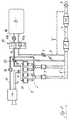
- Reference number 1 thus designates an (here four-cylinder reciprocating piston) internal combustion engine, the exhaust gases of which are first passed via exhaust manifolds 2 into (here two parallel side by side) electrically heatable pre-catalysts 3.
- exhaust pipes 4 referred to as first exhaust pipe in FIG. 2
- exhaust pipes 4 ′ FIG. 1
- the internal combustion engine exhaust gases then enter a main catalytic converter 5 and from there through an exhaust pipe 4, which has at least one silencer 19, finally into the Surroundings.
- a shutoff flap 6 is provided in the exhaust line 4 downstream of the sound damper 19, by means of which the exhaust line 4 can be shut off essentially completely, ie when the shutoff flap 6 is closed, the exhaust gas flow flowing through the muffler 19 cannot get into the environment.
- the exhaust gas flow conducted in the exhaust gas line 4 ′ is conducted via a branch line 7 branching off upstream of the main catalytic converter 5 into a storage volume 8.
- the exhaust gas flow with the shut-off flap 6 closed can also be taken downstream of the main catalytic converter 5 or - as shown here via the branch line 7 ′ shown in dashed lines - downstream of the silencer 19 from the exhaust line 4 and fed to the storage volume 8.
- both a control valve 9 provided in the branch line 7 and a further shut-off valve 10a designed as a three-way valve 10 must be suitably connected for this purpose, ie these two valves 9, 10a, the function of which will be discussed in more detail later, must flow through the exhaust gas release the branch line 7 at least partially.
- the introduction of the exhaust gas flow just described is intended in the storage volume 8 especially after a (cold) start of the Internal combustion engine 1, so if the pre-catalysts 3 and the main catalyst 5 have not yet reached their light-off temperature and thus are unable to remove harmful exhaust gas components (especially hydrocarbons) to convert for a certain period of time (e.g. 25 Seconds).
- a certain period of time e.g. 25 Seconds.
- the locking flap 6 is opened so that then the exhaust gas stream is cleaned, i.e. of at least the essential ones Free pollutant components, is discharged into the environment.
- the storage volume can 8 to be emptied for a later (new) start or cold start the internal combustion engine 1 to be able to again during the said Time span of, for example, 25 seconds of exhaust gas flow take.
- This required emptying of the storage volume 8 can either in the suction system 11 of the internal combustion engine 1 or in the exhaust pipe 4 'into it.
- One of the storage volume is provided for this 8 branching drain line 17, which is in a branch valve 20th in a first line branch 17 'opening into the suction system 11 and in branches a second line branch 17 ′′ opening into the exhaust gas line 4 ′.
- the amount of exhaust gas stored in the storage volume 8 is either for "cleaning" (or aftertreatment) by the then functional Main catalyst 5 out, or alternatively in the intake system 11 of the internal combustion engine 1 initiated.
- the previously in the storage volume 8 stored amount of exhaust gas thus when this storage volume is emptied 8 suitable for repeated post-combustion fed to the internal combustion engine combustion chambers for combustion Fresh gas stream added, preferably at such operating points the internal combustion engine 1, in which this admixture for a flawless Run of the internal combustion engine 1 is not a hindrance.
- the other elements shown in FIG. 1 in the periphery of the internal combustion engine 1 are briefly explained:
- the (here four) combustion chambers of the internal combustion engine 1 are supplied with fresh gas via the intake system 11 already mentioned.
- a throttle valve 13 is provided in an intake line 12 leading to the intake system 11 for controlling the power of the internal combustion engine 1.
- a conventional intake air filter 14 At the free end of the intake line 12 there is a conventional intake air filter 14.
- a secondary air line 15 which opens into the exhaust manifold 2 and is known to the person skilled in the art, branches off, in which, as usual, a secondary air pump 16 is provided, but for the present invention is immaterial.
- a vacuum pump 18 can be seen in this in addition to a shut-off valve 10b, which in turn is part of the three-way valve 10 already mentioned or forms this three-way valve 10 together with the other already mentioned shut-off valve 10a If the shut-off valve 10a is now closed and the shut-off valve 10b is open, ie if the three-way valve 10 assumes the switch position shown in FIG. 1 , the storage volume 8 is sucked empty and thus evacuated when this vacuum pump 18 is operated at the same time, since this vacuum pump 18 adopts with its suction side the storage volume 8 is connected. As already mentioned, the vacuum pump 18 then conveys the amount of exhaust gas located in the storage volume 8 via the emptying line 17 either into the suction system 11 or into the exhaust line 4 '.
- a feed pump (already shown in the prior art mentioned at the outset) can additionally be provided, which enables the accumulation of exhaust gas amount to be stored in the storage volume 8 under excess pressure, as a result of which this storage volume 8 can be dimensioned smaller.
- a feed pump is usually shown in FIG. 2 , which will be explained later, under reference number 24.
- a less powerful feed pump (24) can now be used, or - as in DE 43 42 296 C1, which has also already been mentioned - the internal combustion engine 1 can be adapted by adapting its valve timing to compress the exhaust gas are used after an absolutely safe introduction of the exhaust gas flow into the storage volume 8 is ensured by the vacuum prevailing initially (ie when the internal combustion engine 1 is started) in the storage volume 8.
- An electronic control unit in particular, is not shown in the figure, among others the shut-off flap 6 and the three-way valve 10, i.e. the check valves 10a and 10b positioned according to the respective requirements.
- This Control unit can also - preferably using the signals of a in particular provided in the storage volume 8 and the respective current one
- the pressure sensor detecting the pressure value here - the appropriate control the control valve 9 and the vacuum pump 18.
- this control unit (possibly using further signals or boundary conditions) by suitable control of the control valve 9 in the mouth area the branch line 7 or 7 "into the exhaust line 4 'or 4 one set an approximately constant vacuum of, for example, 0.75 bar.
- this control unit can ensure that this emptying and the associated admixture the amount of exhaust gas collected in the storage volume 8 for the internal combustion engine combustion chambers fresh gas flow supplied only in those operating points the internal combustion engine 1 takes place in which this admixture is not a hindrance to the smooth running of the internal combustion engine. Furthermore, in the subsequent build-up of the negative pressure in the storage volume 8 said control unit operates the vacuum pump Monitor 18 such that the desired negative pressure in the storage volume 8 is generated in the desired order.
- the conveying side should be connected to the environment be, for example.
- the drain line 17 and the exhaust pipe 4.
- the delivery side of the vacuum pump 18 with the suction system 11 Internal combustion engine 1 is connectable, requires a reduced pump output if, in addition - as is known to the person skilled in the art - in the Suction system 11 at a variety of engine operating points (and particularly intensively at idle) prevailing negative pressure becomes.
- the control unit already mentioned can be the vacuum pump 18 operate appropriately.
- the detailed structure of the storage volume 8 is not to be discussed in detail. In essence, this can be a suitable vacuum storage that is stable when the evacuation is complete.
- an absolute tightness is required not only of the vacuum accumulator or the accumulator volume 8, but also of the check valves 10a, 10b (or the three-way valve 10) as well as the drain line 17 and the branch line 7.
- an adsorber material can also be provided in the storage volume 8, which itself stores at least one undesired exhaust gas component for a certain period of time or, as known to the person skilled in the art, for example, as activated carbon, has an adsorbent effect on pollutants.
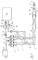
- FIG. 2 and the essential differences of this second exemplary embodiment compared to that according to FIG. 1 are now described: While in normal continuous engine operation the internal combustion engine exhaust gases ultimately reach the environment through the so-called first exhaust pipe 4, as shown by the flow arrow, via the main catalytic converter 5 and via the muffler 19, the internal combustion engine will also start during this 1 subsequent "critical" period, during which neither the pre-catalytic converters 3 nor the main catalytic converter 5 have reached their starting or operating temperature, the shut-off flap 6 provided downstream of the muffler 19 in the exhaust pipe 4 is closed, so that the first exhaust pipe 4 is connected to it Is essentially completely closed off. When the shut-off flap 6 is closed, the exhaust gas flow flowing through the muffler 19 cannot get into the environment, but is directed into a storage volume 8. In the exemplary embodiment according to FIG. 2, this takes place in the following way:
- a transition 21 is provided in the first exhaust line 4 into a second exhaust line 22, into which the exhaust gas flow - as shown by flow arrows - enters with the shut-off valve 6 closed.
- This second exhaust line 22 is arranged coaxially or concentrically to the first exhaust line 4 or envelops the first exhaust line 4, an annular space (not specified in more detail) being present between the outer wall of the first exhaust line 4 and the inner wall of the second exhaust line 22, through which the internal combustion engine exhaust gases then be guided in the second exhaust line 22.
- This second exhaust line 22 extends from the transfer line 21 in the direction of the internal combustion engine 1 (back) to a so-called diversion 23, which is upstream of the pre-catalytic converter 3 on the left-hand side with respect to the flow direction in the second exhaust-gas line 22, and for the pre-catalytic converter on the right-hand side 3 is provided between this pre-catalyst 3 and the internal combustion engine 1.
- the internal combustion engine exhaust system shown is thus double-walled, with not only the exhaust line 4 but also the exhaust gas purification devices in the form of the main catalytic converter 5 and the pre-catalytic converter 3 on the right being encased by the exhaust gas line 22.
- coaxially enveloping second exhaust line 22 now closes the in Connection with the first exemplary embodiment already explained branch line 7, which ultimately also in the storage volume 8, which has also already been explained empties.
- branch line 7 which ultimately also in the storage volume 8
- the shut-off flap 6 is closed, the internal combustion engine exhaust gases via the second exhaust line 22 and the adjoining one Branch line 7 introduced into the storage volume 8.
- the one provided in the branch line 7 as a three-way valve 10 formed check valve 10a can be switched suitably, i.e. this Check valve 10a must allow the flow of exhaust gas flow through the branch line 7 release.
- the introduction of the exhaust gas flow just described is intended in the storage volume 8 especially after a (cold) start the internal combustion engine 1, so if the pre-catalysts 3 and the main catalyst 5 have not yet reached their light-off temperature and thus are unable to remove harmful exhaust gas components (especially hydrocarbons) to convert for a certain period of time (e.g. 25 Seconds).
- a certain period of time e.g. 25 Seconds.
- the locking flap 6 is opened so that then the exhaust gas stream is cleaned, i.e. of at least the essential ones Free pollutant components, is discharged into the environment.
- the storage volume can 8 to be emptied for a later (new) start or cold start the internal combustion engine 1 to be able to again during the said Time span of, for example, 25 seconds of exhaust gas flow take.
- This required emptying of the storage volume 8 takes place in this second exemplary embodiment, only in the suction system 11 the internal combustion engine 1, namely via the drain line 17, wherein a targeted quantity control of those taken from the storage volume 8 and the suction system 11 fed and thus recirculated exhaust gas amount by means of a control valve provided in the drain line 17 25 takes place.
- the vacuum pump 18 In the emptying line 17 there is also the vacuum pump 18 already explained in connection with the exemplary embodiment according to FIG. 1.
- the pre-catalysts 3 generally an exhaust gas cleaning device
- the amount of exhaust gas previously collected in the storage volume 8 was removed from the storage volume 8 - an essentially absolute vacuum was created with this vacuum pump 18 in the storage volume 8.
- the exhaust system is partially double-walled is, so that the engine exhaust gas in this area in one first exhaust pipe 4, which contains the exhaust gas purification device (s), led away from the internal combustion engine 1 and coaxially in a second this first extending exhaust pipe 22 in the manner of a counterflow heat exchanger returned in the direction of the internal combustion engine 1, ultimately, however, is introduced into the storage volume 8.
- the first exhaust pipe 4 is the inner one and the second one Exhaust line 22 around the outer exhaust line of the double-walled, an exhaust system having an annular space. Rather can also the first exhaust line 4 on the outside and the second exhaust line 22 be provided on the inside, the latter then the exhaust gas purification devices, i.e. the main catalytic converter 5 and the precatalyst (s) 3 would penetrate.
Description
Die Erfindung betrifft eine Abgasanlage einer Brennkraftmaschine mit einem Speichervolumen, gemäß der Merkmale im Oberbegriff des Patentanspruchs 1.The invention relates to an exhaust system of an internal combustion engine with a storage volume, according to the features in the preamble of claim 1.
Zum bekannten Stand der Technik wird neben der DE 43 42 296 C1, der DE 40 25 565 A1 auf die GB 1 349 051 und insbesondere auf die US 3,645,098, von der diese Anmeldung ausgeht, verwiesen.In addition to DE 43 42 296 C1, DE 40 25 becomes the known prior art 565 A1 to GB 1 349 051 and in particular to US 3,645,098, of which this Registration runs out, referenced.
Bekanntlich müssen die Abgase einer Kraftfahrzeug-Brennkraftmaschine gereinigt werden, d. h. zumindest teilweise von schädlichen Komponenten befreit werden, wofür insbesondere Abgaskatalysatoren zum Einsatz kommen. Bekanntlich benötigen diese Abgaskatalysatoren eine gewisse Betriebstemperatur, damit sie ihre Funktion, schädliche Abgaskomponenten zu konvertieren, erfüllen können. Diese sog. Anspringtemperatur erreichen moderne Abgaskatalysatoren direkt im Anschluss an einen (Kalt-)Start der Brennkraftmaschine in üblichen Abgastestzyklen erst nach ca. 25 Sek., so dass während dieses Zeitraumes die im folgenden auch als "kritische" Zeitspanne bezeichnet wird, das Brennkraftmaschinenabgas quasi ungereinigt in die Umgebung gelangt.As is known, the exhaust gases of a motor vehicle internal combustion engine have to be cleaned become, d. H. are at least partially freed from harmful components, for which exhaust gas catalysts are used in particular. Need to know these catalytic converters have a certain operating temperature so that they have their Function to convert harmful exhaust gas components. This so-called light-off temperatures reach modern exhaust gas catalysts directly afterwards to a (cold) start of the internal combustion engine in normal exhaust gas test cycles only after approx. 25 seconds, so that the following also during this period is referred to as the "critical" period of time, the engine exhaust gas quasi got into the environment unpurified.
Als Abhilfemaßnahme für diese Problematik wurde bereits in der US 3,645,098 vorgeschlagen, das Brennkraftmaschinenabgas während dieser genannten (kritischen) Zeitspanne von beispielsweise 25 Sek., in ein Speichervolumen zu fördern und dort solange zu speichern, bis der Abgaskatalysator seine Anspringtemperatur erreicht hat bzw. allgemein bis die Abgasreinigungsvorrichtung betriebsbereit ist. Danach kann die sich im Speichervolumen befindende Abgasmenge der dann funktionsbereiten Abgasreinigungsvorrichtung zur Reinigung und/oder der Brennkraftmaschine (bzw. deren Brennräumen) zur nochmaligen Verbrennung zugeführt werden.As a remedial measure for this problem, it has already been proposed in US 3,645,098 the internal combustion engine exhaust gas during this (critical) Time span of, for example, 25 seconds to convey into a storage volume and there save until the catalytic converter reaches its light-off temperature has or generally until the exhaust gas purification device is ready for operation. After that the amount of exhaust gas in the storage volume can then be ready for operation Emission control device for cleaning and / or the internal combustion engine (or their combustion chambers) for further combustion.
Das Speichervolumen ist einem Blasebalg (Luftballon) ähnlich, der von einer Pumpe leergesaugt und von einem Sperrventil an dessen Ausgang gasleer gehalten werden kann. Nach dem Start der Brennkraftmaschine verschließt eine Klappe hinter der Abgasreinigungsvorrichtung, dass das Abgas in das freileitende Rohr, derart, so dass das Abgas durch eine weitere Leitung in das Speichervolumen geführt wird, welches vom Abgas aufgeblasen wird. Nachteilig an dieser Lösung ist das unkontrollierte Aufblasen des Speichervolumens mit Abgas. Abhängig vom Füllgrad des Speichervolumens liegen unterschiedliche Druckverhältnisse im Abgasstrang an, die den Ladungswechsel der Brennkraftmaschine beeinflussen. Dies ist besonders nach einem Start (Neustart) der Brennkraftmaschine von Nachteil, da die Gemischbildungsvorgänge negativ beeinflusst werden, woraus ein sehr unruhiger Brennkraftmaschinenlauf resultieren kann.The storage volume is similar to that of a bellows (that of a pump) sucked empty and kept empty by a check valve at the outlet can be. After the internal combustion engine starts, a flap closes behind the exhaust gas purification device that the exhaust gas into the overhead pipe, such that the exhaust gas through a further line into the storage volume is led, which is inflated by the exhaust gas. The disadvantage of this solution is the uncontrolled inflation of the storage volume with exhaust gas. Depending on the The degree of filling of the storage volume has different pressure ratios in the exhaust system that influence the charge change of the internal combustion engine. This is particularly disadvantageous after a start (restart) of the internal combustion engine, because the mixture formation processes are negatively influenced, resulting in a very restless Internal combustion engine run can result.
Aufgabe der vorliegenden Erfindung ist es, nach dem Start der Brennkraftmaschine definierte Druckverhältnisse im Abgasstrang während einer Befüllung des Speichervolumens mit Abgas vorliegen zu haben. Diese Aufgabe wird durch das Merkmal im kennzeichnenden Teil des Patentanspruchs 1 gelöst. The object of the present invention is after the start of the internal combustion engine Defined pressure ratios in the exhaust line during filling of the storage volume to have with exhaust gas. This task is characterized by the feature in characterizing part of claim 1 solved.
So kann in einer den Brennkraftmaschinen-Abgasstrom zum Speichervolumen führenden Zweigleitung ein Regelventil zur dosierten Befüllung des Speichervolumens vorgesehen sein, wodurch anschließend an einen Start der Brennkraftmaschine bei der damit gewünschterweise einhergehenden Befüllung des Speichervolumens der darin zunächst vorliegende Unterdruck nicht schlagartig, sondern quasi dosiert abgebaut wird. Hierdurch ist ein Absaugen von Brennkraftmaschinen-Abgas aus der Brennkraftmaschinen-Abgasleitung über einen längeren Zeitraum möglich. Bevorzugt ist zur bestmöglichen Umsetzung dieses Verfahrens neben einem den Druckwert im Speichervolumen erfassenden Druckfühler eine die Unterdruckpumpe und/oder das Regelventil anhand der Druckfühler-Signale geeignet steuernde Steuereinheit vorgesehen.So can the internal combustion engine exhaust gas flow to the storage volume leading branch line a control valve for metered filling of the Storage volume may be provided, which then follows a start the internal combustion engine with the associated desired Filling the storage volume the negative pressure initially present therein not abruptly, but quasi-dosed degradation. This is a suction of internal combustion engine exhaust gas from the internal combustion engine exhaust pipe possible over a longer period. Preference is given to the best possible Implementation of this method in addition to a pressure value in the Storage volume-sensing pressure sensor a the vacuum pump and / or suitably controlling the control valve based on the pressure sensor signals Control unit provided.
Im übrigen kann im Speichervolumen ein geeignetes Adsorbermaterial für eine unerwünschte Abgaskomponente vorgesehen sein, so daß die in das Speichervolumen eingebrachten Abgase zugleich zumindest teilweise gereinigt werden, ehe sie nach Ablauf der gewünschten bzw. erforderlichen Speicherungs-Zeitspanne wieder in die Abgasleitung der Brennkraftmaschine abgegeben werden.Otherwise, a suitable adsorber material can be stored in the storage volume an undesirable exhaust gas component may be provided, so that in the Storage volume introduced exhaust gases at least partially cleaned at the same time before they expire after the desired or required storage period back into the exhaust pipe of the internal combustion engine be delivered.
In einer weiteren besonders vorteilhaften Ausführungsform kann die Abgasanlage bereichsweise doppelwandig ausgeführt sein, so daß zwei im wesentlichen koaxial zueinander verlaufende Abgasleitungen vorliegen, wobei über die erste, vorzugsweise innere Abgasleitung das Abgas von der Brennkraftmaschine weggeführt und über die zweite, vorzugsweise äußere Abgasleitung zum Speichervolumen hingeführt wird.In a further particularly advantageous embodiment, the exhaust system partially double-walled, so that two essentially Exhaust gas lines running coaxially to one another are present, wherein Via the first, preferably inner exhaust pipe, the exhaust gas from the internal combustion engine led away and via the second, preferably outer exhaust pipe is led to the storage volume.
Mit einer bereichsweise doppelwandig ausgebildeten Abgasanlage - eine solche ist bspw. in der DE-AS 22 22 498 gezeigt - werden die Brennkraftmaschinen-Abgase somit zunächst in einer ersten Abgasleitung von der Brennkraftmaschine weggeführt und danach in einer koaxial bzw. konzentrisch zu dieser ersten Abgasleitung verlaufenden zweiten Abgasleitung zum Speichervolumen geleitet, und zwar zurück in Richtung zur Brennkraftmaschine. Dieser doppelwandige Abschnitt der Abgasanlage gleicht somit einem Gegenstrom-Wärmetauscher. Durch diese Maßnahme wird die Abgasanlage im doppelwandigen Abschnitt verstärkt erwärmt, was einem schnelleren Anspringen des oder der Abkaskatalysatoren förderlich ist, d.h. die Abgasreinigungsvorrichtung erreicht mit dieser Maßnahme ihre Betriebstemperatur früher.With a partially double-walled exhaust system - one such is shown, for example, in DE-AS 22 22 498 - the internal combustion engine exhaust gases thus initially in a first exhaust line from the internal combustion engine led away and then in a coaxial or concentric of this first exhaust line running second exhaust line to the storage volume passed, namely back towards the internal combustion engine. This double-walled section of the exhaust system thus resembles a counterflow heat exchanger. By this measure, the exhaust system in the double-walled section warms up, which means faster start of the catalytic converter is beneficial, i.e. the exhaust gas purification device reaches its operating temperature earlier with this measure.
Mit dieser verstärkten Erwärmung einher geht eine verstärkte Abkühlung des zum Speichervolumen geführten Abgasstromes, wodurch das Volumen der tatsächlich zu speichernden Abgasmenge bzw. Abgasmasse nach der physikalischen Zustandsgleichung für Gase verringert wird. im räumlich begrenzeten Speichervolumen kann somit eine größere Abgasmenge bzw. Abgasmasse gespeichert werden. Dabei ist es besonders vorteilhaft, wenn die Überleitung zwischen der ersten und der zweiten Abgasleitung bezüglich der Brennkraftmaschine stromab der Abgasreinigungsvorrichtung vorgesehen ist, während sich eine Ausleitung aus der zweiten Abgasleitung in eine zum Speichervolumen führende Zweigleitung zwischen der Brennkraftmaschine und der Abgasreinigungsvorrichtung befindet. Dann ist nämlich die Abgasanlage auch im Bereich der Abgasreinigungsvorrichtung doppelwandig ausgebildet, wodurch letztere eine besonders intensive Erwärmung durch die Brennkraftmaschinen-Abgase erfährt. This increased warming is accompanied by an increased cooling of the to the storage volume led exhaust gas flow, whereby the volume of the Exhaust gas volume or exhaust gas mass actually to be stored according to the physical State equation for gases is reduced. in a limited space Storage volume can therefore a larger amount of exhaust gas or exhaust gas mass get saved. It is particularly advantageous if the Transition between the first and the second exhaust pipe with respect to the Internal combustion engine provided downstream of the exhaust gas purification device is, while a diversion from the second exhaust line into a Storage volume leading branch line between the internal combustion engine and the exhaust gas purification device. Then there is the exhaust system double-walled also in the area of the exhaust gas cleaning device trained, whereby the latter through a particularly intense heating experiences the engine exhaust gases.
Ein weiterer Vorteil einer erfindungsgemäßen Abgasanlage liegt darin, daß die bereichsweise doppelwandige Abgasanlage bereits selbst einen Teil des Speichervolumens bildet, und zwar mit minimalem zusätzlichem Raumbedarf, so daß das eigentliche Speichervolumen dementsprechend kleiner gestaltet werden kann. Im übrigen ist es besonders empfehlenswert, die zunächst während der sog. "kritischen" Zeitspanne gespeicherte Abgasmenge nach Erreichen der Funktionsbereitschaft der Abgasreinigungsvorrichtung der Brennkraftmaschine zur (nochmaligen) Nachverbrennung zuzuführen, so daß das Speichervolumen bevorzugt nahe der Brennkraftmaschine angeordnet werden sollte. Dann ist vorteilhafterweise mit einer erfindunsgemäßen Abgasanlage eine relativ einfache Abgasführung zum nahe der Brennkraftmaschine angeordneten Speichervolumen möglich.Another advantage of an exhaust system according to the invention is that the partially double-walled exhaust system itself is part of the Storage volume forms, with a minimal additional space requirement, so that the actual storage volume is made smaller accordingly can be. For the rest, it is particularly recommended to start with amount of exhaust gas stored during the so-called "critical" period after the operational readiness of the exhaust gas cleaning device has been reached to feed the internal combustion engine for (re) combustion, so that the storage volume is preferably arranged near the internal combustion engine should be. Then it is advantageous with one according to the invention Exhaust system is a relatively simple exhaust system for close to the internal combustion engine arranged storage volume possible.
Näher erläutert wird die Erfindung anhand zweier bevorzugter Ausführungsbeispiele, welche in den beigefügten Figuren 1, 2 jeweils in Form einer Prinzipskizze dargestellt sind. Dabei sind gleiche Bauelemente stets mit den gleichen Bezugsziffern versehen.The invention is explained in more detail with reference to two preferred exemplary embodiments, which are each shown in the form of a schematic diagram in the attached FIGS. 1, 2 . The same components are always provided with the same reference numbers.
So ist mit der Bezugsziffer 1 eine (hier vierzylindrige Hubkolben-) Brennkraftmaschine
bezeichnet, deren Abgase über Abgaskrümmer 2 zunächst in
(hier zwei parallel nebeneinander vorgesehene) elektrisch beheizbare Vorkatalysatoren
3 geleitet werden. Über Abgasleitungen 4 (in Figur 2 als erste
Abgasleitung bezeichnet) bzw. Abgasleitungen 4' (Figur 1) gelangen die
Brennkraftmaschinen-Abgase danach in einen Hauptkatalysator 5 und von
diesem aus durch eine Abgasleitung 4, die zumindest einen Schalldämpfer
19 aufweist, letztendlich in die Umgebung. Stromab des Schalldämpers 19
ist in der Abgasleitung 4 eine Sperrklappe 6 vorgesehen, mit Hilfe derer die
Abgasleitung 4 im wesentlichen vollständig absperrbar ist, d.h. bei geschlossener
Sperrklappe 6 kann der den Schalldämpfer 19 durchströmende Abgasstrom
nicht in die Umgebung gelangen.Reference number 1 thus designates an (here four-cylinder reciprocating piston) internal combustion engine, the exhaust gases of which are first passed via
Im folgenden wird nun auf das Ausführungsbeispiel nach Figur 1 verwiesen.
Hier wird bei geschlossener Sperrklappe 6 der in der Abgasleitung 4' geführte
Abgasstrom über eine stromauf des Hauptkatalysators 5 von dieser
abzweigenden Zweigleitung 7 in ein Speichervolumen 8 geleitet. Alternativ
kann der Abgasstrom bei geschlossener Sperrklappe 6 auch stromab des
Hauptkatalystors 5 oder - wie hier über die gestrichelt dargestellte Zweigleitung
7' - stromab des Schalldämpers 19 aus der Abgasleitung 4 entnommen
und dem Speichervolumen 8 zugeführt werden. Selbstverständlich müssen
hierfür sowohl ein in der Zweigleitung 7 vorgesehenes Regelventil 9 als auch
ein weiteres, als Dreiwegeventil 10 ausgebildetes Sperrventil 10a geeignet
geschaltet sein, d.h. diese beiden Ventile 9, 10a, auf deren Funktion später
noch näher eingegangen wird, müssen den Fluß des Abgasstromes durch
die Zweigleitung 7 zumindest teilweise freigeben.In the following, reference is now made to the exemplary embodiment according to FIG. 1 . Here, when the shut-
Wie eingangs erläutert soll die soeben beschriebene Einleitung des Abgasstromes
in das Speichervolumen 8 insbesondere nach einem (Kalt-)Start der
Brennkraftmaschine 1, wenn also die Vorkatalysatoren 3 und der Hauptkatalysator
5 ihre Anspringtemperatur noch nicht erreicht haben und somit
nicht in der Lage sind, schädliche Abgaskomponenten (insbesondere Kohlenwasserstoffe)
zu konvertieren, für eine gewisse Zeitspanne (von bspw. 25
Sekunden) erfolgen. Haben nach Ablauf dieser sog. "kritischen" Zeitspanne
zumindest die Vorkatalysatoren 3 ihre Anspringtemperatur erreicht und können
dann ihre Funktion erfüllen, so wird die Sperrklappe 6 geöffnet, so daß
dann der Abgasstrom gereinigt, d.h. von zumindest den wesentlichen
Schadstoffkomponenten befreit, in die Umgebung abgeführt wird. As explained at the beginning, the introduction of the exhaust gas flow just described is intended
in the
Ist der soeben beschriebene Zustand erreicht, so kann das Speichervolumen
8 entleert werden, um für einen späteren (neuerlichen) Start bzw. Kalt-Start
der Brennkraftmaschine 1 wieder in der Lage zu sein, den während der genannten
Zeitspanne von bspw. 25 Sekunden ausgestoßenen Abgasstrom
aufzunehmen. Diese erforderliche Entleerung des Speichervolumens 8 kann
entweder in die Sauganlage 11 der Brennkraftmaschine 1 oder in die Abgasleitung
4' hinein erfolgen. Vorgesehen ist hierfür eine vom Speichervolumen
8 abzweigende Entleerungsleitung 17, die sich in einem Zweigventil 20
in einen ersten in der Sauganlage 11 mündenden Leitungszweig 17' sowie in
einen zweiten in der Abgasleitung 4' mündenden Leitungszweig 17" verzweigt.
In Abhängigkeit von der Schaltstellung des Zweigventiles 20 wird die
zunächst im Speichervolumen 8 gespeicherte Abgasmenge somit entweder
zur "Reinigung" (bzw. Nachbehandlung) durch den dann funktionsfähigen
Hauptkatalysator 5 geführt, oder alternativ in die Sauganlage 11 der Brennkraftmaschine
1 eingeleitet. Im letztgenannten Fall wird die zuvor im Speichervolumen
8 gespeicherte Abgasmenge somit bei Entleerung dieses Speichervolumens
8 zur nochmaligen Nachverbrennung geeignet dosiert dem
den Brennkraftmaschinen-Brennräumen zur Verbrennung zugeführten
Frischgasstrom beigemengt, und zwar bevorzugt in solchen Betriebspunkten
der Brennkraftmaschine 1, in denen diese Beimengung für einen einwandfreien
Lauf der Brennkraftmaschine 1 nicht hinderlich ist.If the state just described is reached, the storage volume can
8 to be emptied for a later (new) start or cold start
the internal combustion engine 1 to be able to again during the said
Time span of, for example, 25 seconds of exhaust gas flow
take. This required emptying of the
In diesem Zusammenhang sollen kurz die weiteren in Figur 1 in der Peripherie
der Brennkraftmaschine 1 dargestellten Elemente erläutert werden:
Über die bereits erwähnte Sauganlage 11 werden wie üblich die (hier vier)
Brennräume der Brennkraftmaschine 1 mit Frischgas versorgt. Ebenfalls wie
üblich ist in einer zur Sauganlage 11 führenden Ansaugleitung 12 eine Drosselklappe
13 zur Leistungssteuerung der Brennkraftmaschine 1 vorgesehen.
Am freien Ende der Ansaugleitung 12 befindet sich ein übliches Ansaug-Luftfilter
14. Von diesem zweigt neben der Ansaugleitung 12 noch eine in
den Abgaskrümmern 2 mündende, dem Fachmann bekannte Sekundärluftleitung
15 ab, in welcher wie üblich eine Sekundärluftpumpe 16 vorgesehen
ist, was jedoch für die vorliegende Erfindung unwesentlich ist.In this context, the other elements shown in FIG. 1 in the periphery of the internal combustion engine 1 are briefly explained: As usual, the (here four) combustion chambers of the internal combustion engine 1 are supplied with fresh gas via the
Zurückkommend auf die oben bereits erwähnte Entleerung des Speichervolumens
8 über die Entleerungsleitung 17 erkennt man in dieser neben einem
Sperrventil 10b, das seinerseits Bestandteil des bereits erwähnten Dreiwegeventiles
10 ist bzw. zusammen mit dem anderen bereits erwähnten Sperrventil
10a dieses Dreiwegeventil 10 bildet, eine Unterdruckpumpe 18.
Ist nun das Sperrventil 10a geschlossen und das Sperrventil 10b geöffnet,
d.h. nimmt das Dreiwegeventil 10 die in Figur 1 dargestellte Schaltstellung
ein, so wird bei gleichzeitigem Betrieb dieser Unterdruckpumpe 18 das Speichervolumen
8 leergesaugt und somit evakuiert, da diese Unterdruckpumpe
18 mit ihrer Saugseite an das Speichervolumen 8 angeschlossen ist. Wie
bereits erwähnt fördert die Unterdruckpumpe 18 dann die sich im Speichervolumen
8 befindende Abgasmenge über die Entleerungsleitung 17 entweder
in die Sauganlage 11 oder in die Abgasleitung 4'.Returning to the above-mentioned emptying of the
Dieses soeben beschriebene Fördern der gespeicherten Abgasmenge aus
dem Speichervolumen 8 in die Sauganlage 11 ist jedoch nicht die einzige
Funktion der Unterdruckpumpe 18, da dies bei geöffnetem Sperrventil 10b
aufgrund des - wie dem Fachmann bekannt ist - zumindest zeitweise in der
Sauganlage 11 (bei zumindest teilweise geschlossener Drosselklappe 13)
vorliegenden Unterdruckes auch quasi selbsttätig erfolgen würde. Eine weitere
Funktion der Unterdruckpumpe 18 ist es vielmehr, im Speichervolumen
8 ein im wesentlichen absolutes Vakuum zu erzeugen, welches anschließend
daran durch entsprechende Schaltung des Dreiwegeventiles 10 bzw.
der beiden Sperrventile 10a, 10b gehalten wird. This just described conveying the stored amount of exhaust gas
the
Bei einem Betrieb der Brennkraftmaschine 1 wird somit - nachdem zumindest
die Vorkatalysatoren 3, allgemein eine Abgasreinigungsvorrichtung, ihre
Betriebstemperatur erreicht haben/hat und nachdem die zuvor im Speichervolumen
8 gesammelte Abgasmenge aus dem Speichervolumen 8 entfernt
wurde - im Speichervolumen 8 ein im wesentlichen absolutes Vakuum erzeugt,
welches aufgrund der absolut dicht geschlossenen Sperrventile 10a,
10b auch nach einem Abstellen der Brennkraftmaschine 1 bis zu deren
nächstem Start gehalten wird.When the internal combustion engine 1 is operating, at least after
the pre-catalysts 3, generally an exhaust gas purification device, their
Have reached / have reached operating temperature and after that in the
Wird nun nach einem - auch längerfristigen - Stillstand die Brennkraftmaschine
1 neu gestartet und werden dann gleichzeitig - wie weiter oben bereits
beschrieben - die Sperrklappe 6 in der Abgasleitung 4 geschlossen sowie
das Regelventil 9 und das Sperrventil 10a geöffnet, so wird aufgrund des
im Speichervolumen 8 vorliegenden Vakuums der den Hauptkatalysator 5
verlassende Abgasstrom in das Speichervolumen 8 gesaugt. Selbstverständlich
wird hierdurch das Vakuum im Speichervolumen 8 kontinuierlich
abgebaut, jedoch ist aufgrund des zumindest anfänglich noch relativ hohen
Unterdruckes im Speichervolumen sichergestellt, daß die in der bereits genannten
"kritischen" Zeitspanne anfallende Abgasmenge sicher in das Speichervolumen
8 gelangt.If the internal combustion engine comes to a standstill even after a long-term shutdown
1 restarted and are then started simultaneously - as already mentioned above
described - the shut-off
Bei geeigneter Dimensionierung bzw. geeignetem Rauminhalt des Speichervolumens
8 kann sogar die gesamte während der "kritischen" Zeitspanne
anfallende Abgasmenge durch das genannte anfängliche Vakuum in das
Speichervolumen 8 gefördert werden; abweichend vom hier gezeigten Ausführungsbeispiel
kann jedoch zusätzlich eine (im eingangs genannten Stand
der Technik bereits gezeigte) Förderpumpe vorgesehen sein, die eine Speicherung
der anfallenden Abgasmenge im Speichervolumen 8 unter Überdruck
ermöglicht, wodurch dieses Speichervolumen 8 kleiner dimensioniert
werden kann. Eine derartige Förderpumpe ist im übigen in der später noch
erläuterten Figur 2 unter der Bezugsziffer 24 dargestellt. Gegenüber dem
bekannten Stand der Technik kann aufgrund der Unterdruckerzeugung im
Speichervolumen 8 nun eine leistungsschwächere Förderpumpe (24) zum
Einsatz kommen oder es kann - wie in der ebenfalls bereits erwähnten
DE 43 42 296 C1 die Brennkraftmaschine 1 durch Anpassung von deren
Ventilsteuerzeiten zur Komprimierung des Abgases verwendet werden,
nachdem durch das zunächst (d.h. beim Start der Brennkraftmaschine 1) im
Speichervolumen 8 herrschende Vakuum eine absolut sichere Einleitung des
Abgasstromes in das Speichervolumen 8 gewährleistet ist.With a suitable dimensioning or a suitable volume of the
Dieser erfindungsgemäße Effekt wird im folgenden in anderen Worten
nochmals erläutert:
Für die beschriebene Befüllung des Speichervolumens 8 mittels des ursprünglich
darin herrschenden, zuvor durch die Unterdruckpumpe 18 erzeugten
und durch die Sperrventile 10a, 10b gehaltenen Vakuums kann nun
das bereits kurz erwähnte Regelventil 9, welches in der Zweigleitung 7 angeordnet
ist, von besonderem Vorteil sein:
In diesem Zusammenhang sei darauf hingewiesen, daß in einer vereinfachten
Ausführungsform auch eine einfache, starre Drosselstelle in der Zweigleitung
7 anstelle des hier gezeigten Regelventiles 9 ausreichend sein kann.
Ferner sei in diesem Zusammenhang auf einen besonderen Vorteil einer
erfindungsgemäßen Abgasanlage mit einem sozusagen als Unterdruckspeicher
wirkenden Speichervolumen 8 hingewiesen:
Wenn nämlich gewährleistet sein muß, daß in der besagten kritischen Zeitspanne
überhaupt kein Abgas in die Umgebung gelangt, so ist dies beim
bekannten Stand der Technik nur dadurch möglich, daß eine in der Abgasleitung
4 erforderliche (und hier mit der Bezugsziffer 6 bezeichnete) Sperrklappe
absolut dicht geschlossen ist. Bei der vorliegenden Erfindung hingegen
ist dieses absolute Dichtheitserfordernis nicht gegeben, da aufgrund des
- ggf. durch das Regelventil 9 gesteuerten - an der Abgasleitung 4 anliegenden
Unterdruckes, der vom geöffnetem Speichervolumen 8 herrührt, das in
dieser Abgasleitung 4 geführte Abgas stets sicher und zuverlässig in das
Speichervolumen 8 abgesaugt wird.If it has to be guaranteed that in the said critical period of time
no exhaust gas gets into the environment at all
known prior art only possible in that in the
Figürlich nicht dargestellt ist eine insbesondere elektronische Steuereinheit,
die u.a. die Sperrklappe 6 sowie das Dreiwegeventil 10, d.h. die Sperrventile
10a und 10b den jeweiligen Anforderungen entsprechend positioniert. Diese
Steuereinheit kann auch - vorzugsweise unter Rückgriff auf die Signale eines
insbesondere im Speichervolumen 8 vorgesehenen und den jeweiligen aktuellen
Druckwert hierin erfassenden Druckfühlers - die geeignete Ansteuerung
des Regelventiles 9 sowie der Unterdruckpumpe 18 übernehmen. Bei einer
Befüllung des Speichervolumens 8 während der "kritischen" Zeitspanne kann
dieses Steuergerät (ggf. zurückgreifend auf weitere Signale oder Randbedingungen)
durch geeignete Ansteuerung des Regelventiles 9 im Mündungsbereich
der Zweigleitung 7 bzw 7" in die Abgasleitung 4' bzw. 4 einen
annähernd konstanten Unterdruck von bspw. 0,75 bar einstellen. Bei einer
späteren Entleerung des Speichervolumens 8 kann diese Steuereinheit sicherstellen,
daß diese Entleerung und die damit verbundene Beimischung
der im Speichervolumen 8 gesammelten Abgasmenge zum den Brennkraftmaschinen-Brennräumen
zugeführten Frischgasstrom nur in denjenigen Betriebspunkten
der Brennkraftmaschine 1 erfolgt, in denen diese Beimengung
für einen einwandfreien Lauf der Brennkraftmaschine nicht hinderlich ist.
Weiterhin kann beim daraufhin folgenden Aufbau des Unterdruckes im Speichervolumen
8 die besagte Steuereinheit den Betrieb der Unterdruckpumpe
18 überwachen, derart, daß im Speichervolumen 8 der gewünschte Unterdruck
in der gewünschten Größenordnung erzeugt wird. In diesem Zusammenhang
sei darauf hingewiesen, daß es grundsätzlich erwünscht ist, nach
erfolgter Entleerung des Speichervolumens 8 während des Betriebes der
Brennkraftmaschine 1 in diesem Speichervolumen 8 einmalig das gewünschte
Vakuum aufzubauen und dieses dann durch Geschlossenhalten
der Sperrventile 10a, 10b über einen langen Zeitraum - insbesondere auch
nach einem Abstellen der Brennkraftmaschine 1 bis zu deren nächstem Start
- zu haften. Es ist jedoch auch möglich, das Vakuum im Speichervolumen 8
laufend zu überwachen und auch bei stillstehender Brennkraftmaschine 1
durch zeitweisen Betrieb der Unterdruckpumpe 18 dafür Sorge zu tragen,
daß im Speichervolumen 8 stets das für einen Neu-Start der Brennkraftmaschine
1 gewünschte (bzw. im Hinblick auf die hiermit erzielbare Verringerung
der Abgasemissionen erforderliche) Vakuum vorliegt. Alternativ ist es
auch möglich, einen Start der Brennkraftmaschine 1 überhaupt nur dann zu
ermöglichen bzw. zuzulassen, wenn im Speichervolumen 8 das gewünschte
Vakuum vorliegt. Ggf. muß also vor einem Start der Brennkraftmaschine 1 -
ähnlich dem Vorglühen bei selbstzündenden Brennkraftmaschinen - zunächst
die Unterdruckpumpe 18 so lange betrieben werden, bis das Vakuum
im Speichervolumen 8 erzeugt ist.An electronic control unit, in particular, is not shown in the figure,
among others the shut-off
Wenn die Unterdruckpumpe 18 auch bei stillstehender Brennkraftmaschine 1
betrieben werden soll, so sollte deren Förderseite mit der Umgebung verbunden
werden, bspw. über die Entleerungsleitung 17" und die Abgasleitung
4. In diesem Zusammenhang sei noch darauf hingewiesen, daß dadurch,
daß die Förderseite der Unterdruckpumpe 18 mit der Sauganlage 11 der
Brennkraftmaschine 1 verbindbar ist, eine verringerte Pumpenleistung benötigt
wird, wenn zusätzlich der - wie dies dem Fachmann bekannt ist - in der
Sauganlage 11 bei einer Vielzahl von Brennkraftmaschinen-Betriebspunkten
(und besonders intensiv im Leerlauf) herrschende Unterdruck mitgenutzt
wird. Im Hinblick hierauf kann die bereits genannte Steuereinheit die Unterdruckpumpe
18 geeignet betreiben.If the
Unter Bezugnahme auf das Ausführungsbeispiel nach Figur 1 sei noch darauf
hingewiesen, daß mit einer stromab des Schalldämpfers 5 von der Abgasleitung
4 abzweigenden Zweigleitung 7' anschließend an einen Start der
Brennkraftmaschine 1 nicht nur der Hauptkatalysator 5 (sowie selbstverständlich
auch die Vorkatalysatoren 3) durch den hindurchgeführten Abgasstrom
in gewünschter Weise erwärmt wird, sondern gleichzeitig der Abgasstrom
abgekühlt wird, wodurch das Volumen der zu speichernden Abgasmenge
(nach der physikalischen Zustandsgleichung für Gase) verringert
wird. Im Speichervolumen 8 kann somit eine größere Abgasmenge, genauer
Abgasmasse gespeichert werden.With reference to the exemplary embodiment according to FIG. 1, it should also be pointed out that with a
Nicht näher eingegangen werden soll auf den detaillierten Aufbau des Speichervolumens
8. Im wesentlichen kann es sich hierbei um einen geeigneten
bei vollständiger Evakuierung stabilen Unterdruckspeicher handeln. Erforderlich
ist selbstverständlich eine idealerweise absolute Dichtheit nicht nur
des Unterdruckspeichers bzw. des Speichervolumens 8, sondem auch der
Sperrventile 10a, 10b (bzw. des Dreiwegeventiles 10) sowie der Entleerungsleitung
17 und der Zweigleitung 7.
Schließlich kann im Speichervolumen 8 noch ein Adsorbermaterial vorgesehen
sein, welches selbst zumindest eine unerwünschte Abgaskomponente
für einen gewissen Zeitraum speichert, bzw. - wie dem Fachmann bspw. als
Aktivkohle bekannt - schadstoffadsorbierend wirkt. The detailed structure of the
Finally, an adsorber material can also be provided in the
Im folgenden wird nun Figur 2 bzw. die wesentlichen Unterschiede dieses
zweiten Ausführungsbeispieles gegenüber demjenigen nach Figur 1 beschrieben:
Während im üblichen Brennkraftmaschinen-Dauerbetrieb die Brennkraftmaschinen-Abgase
durch die hier sog. erste Abgasleitung 4 wie durch den
Strömungspfeil dargestellt über den Hauptkatalysator 5 sowie über den
Schalldämpfer 19 letztendlich in die Umgebung gelangen, wird auch hier
während der genannten sich an einen Start der Brennkraftmaschine 1 anschließenden
"kritischen" Zeitspanne, während derer weder die Vorkatalysatoren
3 noch der Hauptkatalysator 5 ihre bzw. seine Anspring- oder Betriebstemperatur
erreicht haben, die stromab des Schalldämpfers 19 in der
Abgasleitung 4 vorgesehene Sperrklappe 6 geschlossen, so daß die erste
Abgasleitung 4 an dieser Stelle im wesentlichen vollständig abgesperrt ist.
Bei geschlossener Sperrklappe 6 kann der den Schalldämpfer 19 durchströmende
Abgasstrom nicht in die Umgebung gelangen, sondern wird in ein
Speichervolumen 8 geleitet. Dies geschieht beim Ausführungsbeispiel nach
Figur 2 auf folgende Weise:In the following, FIG. 2 and the essential differences of this second exemplary embodiment compared to that according to FIG. 1 are now described:
While in normal continuous engine operation the internal combustion engine exhaust gases ultimately reach the environment through the so-called
Zwischen dem Schalldämper 19 und der Abgasklappe 6, d.h. stromauf derselben,
ist in der ersten Abgasleitung 4 eine Überleitung 21 in eine zweite
Abgasleitung 22 vorgesehen, in welche der Abgasstrom - wie durch Strömungspfeile
dargestellt - bei geschlossener Sperrklappe 6 gelangt. Diese
zweite Abgasleitung 22 ist koaxial bzw. konzentrisch zur ersten Abgasleitung
4 angeordnet bzw. umhüllt die erste Abgasleitung 4, wobei zwischen der
Außenwand der ersten Abgasleitung 4 und der Innenwand der zweiten Abgasleitung
22 ein nicht näher bezeichneter Ringraum vorliegt, durch den die
Brennkraftmaschinen-Abgase dann in der zweiten Abgasleitung 22 geführt
werden. Diese zweite Abgasleitung 22 erstreckt sich dabei von der Überleitung
21 in Richtung zur Brennkraftmaschine 1 (zurück) bis zu einer sog.
Ausleitung 23, die am hier linksseitigen Vorkatalysator 3 bezüglich der Strömungsrichtung
in der zweiten Abgasleitung 22 stromauf desselben, und für
den hier rechtsseitigen Vorkatalysator 3 zwischen diesem Vorkatalysator 3
und der Brennkraftmaschine 1 vorgesehen ist.
Im Bereich zwischen der Ausleitung 23 und der Überleitung 21 ist die gezeigte
Brennkraftmaschinen-Abgasanlage somit doppelwandig ausgebildet,
wobei nicht nur die Abgasleitung 4, sondern auch die Abgasreinigungsvorrichtungen
in Form des Hauptkatalysators 5 sowie des hier rechten Vorkatalysators
3 von der Abgasleitung 22 umhüllt sind.Between the
In the area between the
An die Ausleitung 23 bzw. an das Ende der die erste Abgasleitung 4 bevorzugt
koaxial umhüllenden zweiten Abgasleitung 22 schließt sich nun die in
Verbindung mit dem ersten Ausführungsbeispiel bereits erläuterte Zweigleitung
7 an, die letzlich im ebenfalls bereits erläuterten Speichervolumen 8
mündet. Bei geschlossener Sperrklappe 6 werden somit die Brennkraftmaschinen-Abgase
über die zweite Abgasleitung 22 sowie die sich daran anschließende
Zweigleitung 7 in das Speichervolumen 8 eingeleitet. Selbstverständlich
muß auch hier das in der Zweigleitung 7 vorgesehene als Dreiwegeventil
10 ausgebildete Sperrventil 10a geeignet geschaltet sein, d.h. dieses
Sperrventil 10a muß den Fluß des Abgasstromes durch die Zweigleitung
7 freigeben. In diesem Zusammenhang sei noch auf die in der Zweigleitung
7 vorgesehene Förderpumpe 24 hingewiesen, mit Hilfe derer das in das
Speichervolumen 8 eingeleitete Brennkraftmaschinen-Abgas im Speichervolumen
8 komprimiert werden kann, so daß dieses Speichervolumen 8 einen
für die Speicherung der in der genannten "kritischen" Zeitspanne anfallenden
Abgasmenge noch vertretbaren Rauminhalt besitzt.At the
Wie eingangs erläutert soll die soeben beschriebene Einleitung des Abgasstromes
in das Speichervolumen 8 insbesondere nach einem (Kalt-) Start
der Brennkraftmaschine 1, wenn also die Vorkatalysatoren 3 und der Hauptkatalysator
5 ihre Anspringtemperatur noch nicht erreicht haben und somit
nicht in der Lage sind, schädliche Abgaskomponenten (insbesondere Kohlenwasserstoffe)
zu konvertieren, für eine gewisse Zeitspanne (von bspw. 25
Sekunden) erfolgen. Haben nach Ablauf dieser sog. "kritischen" Zeitspanne
zumindest die Vorkatalysatoren 3 ihre Anspringtemperatur erreicht und können
dann ihre Funktion erfüllen, so wird die Sperrklappe 6 geöffnet, so daß
dann der Abgasstrom gereinigt, d.h. von zumindest den wesentlichen
Schadstoffkomponenten befreit, in die Umgebung abgeführt wird.As explained at the beginning, the introduction of the exhaust gas flow just described is intended
in the
Ist der soeben beschriebene Zustand erreicht, so kann das Speichervolumen
8 entleert werden, um für einen späteren (neuerlichen) Start bzw. Kalt-Start
der Brennkraftmaschine 1 wieder in der Lage zu sein, den während der genannten
Zeitspanne von bspw. 25 Sekunden ausgestoßenen Abgasstrom
aufzunehmen. Diese erforderliche Entleerung des Speichervolumens 8 erfolgt
bei diesem zweiten Ausführungsbeispiel lediglich in die Sauganlage 11
der Brennkraftmaschine 1, und zwar über die Entleerungsleitung 17, wobei
eine gezielte Mengensteuerung der aus dem Speichervolumen 8 entnommenen
und der Sauganlage 11 zugeführten und somit rückgeführten Abgasmenge
mittels eines in der Entleerungsleitung 17 vorgesehenen Steuerventiles
25 erfolgt.If the state just described is reached, the storage volume can
8 to be emptied for a later (new) start or cold start
the internal combustion engine 1 to be able to again during the said
Time span of, for example, 25 seconds of exhaust gas flow
take. This required emptying of the
In der Entleerungsleitung 17 befindet sich auch hier die in Verbindung mit
dem Ausführungsbeispiel nach Figur 1 bereits erläuterte Unterdruckpumpe
18. Bei einem Betrieb der Brennkraftmaschine 1 wird somit - nachdem zumindest
die Vorkatalysatoren 3, allgemein eine Abgasreinigungsvorrichtung,
ihre Betriebstemperatur erreicht haben/hat und nachdem die zuvor im Speichervolumen
8 gesammelte Abgasmenge aus dem Speichervolumen 8 entfernt
wurde - mit dieser Unterdruckpumpe 18 im Speichervolumen 8 ein im
wesentlichen absolutes Vakuum erzeugt. Dieses wird aufgrund der absolut
dicht geschlossenen Sperrventile 10a, 10b auch nach einem Abstellen der
Brennkraftmaschine 1 bis zu deren nächstem Start gehalten oder ggf. vor
einem Start der Brennkraftmaschine 1 durch Inbetriebnahme der Unterdruckpumpe
18 neuerlich erzeugt.In the emptying
Zurückkommend auf die Einleitung des Brennkraftmaschinen-Abgases in
das Speichervolumen 8 während der genannten, sich an einen Start der
Brennkraftmaschine 1 anschließenden sog. "kritischen" Zeitspanne seien
abschließend nochmals kurz die wesentlichen Vorteile der erfindungsgemäß
bereichsweise doppelwandig ausgeführten Abgasanlage wiederholt:
Dabei sei ausdrücklich darauf hingeweisen, daß diese genannten Effekte
dadurch auftreten, daß die Abgasanlage bereichsweise doppelwandig ausgeführt
ist, so daß das Brennkraftmaschinen-Abgas in diesem Bereich in einer
ersten Abgasleitung 4, die die Abgasreinigungsvorrichtung(en) enthält,
von der Brennkraftmaschine 1 weggeführt und in einer zweiten koaxial zu
dieser ersten verlaufenden Abgasleitung 22 nach Art eines Gegenstromwärmetauschers
wieder in Richtung der Brennkraftmaschine 1 zurückgeführt,
dabei letzendlich jedoch in das Speichervolumen 8 eingeleitet wird.
Nicht unbedingt notwendig ist es zur Erzielung dieser vorteilhaften Effekte,
daß es sich bei der ersten Abgasleitung 4 um die innere und bei der zweiten
Abgasleitung 22 um die äußere Abgasleitung der bereichsweise doppelwandigen,
einen Ringraum aufweisenden Abgasanlage handelt. Vielmehr kann
auch die erste Abgasleitung 4 außenliegend und die zweite Abgasleitung 22
innenliegend vorgesehen sein, wobei die letztgenannte dann die Abgasreinigungsvorrichtungen,
d.h. den Hauptkatalysator 5 und den oder die Vorkatalysator(en)
3 durchdringen würde.It should be expressly pointed out that these effects mentioned
occur in that the exhaust system is partially double-walled
is, so that the engine exhaust gas in this area in one
Selbstverständlich sind eine Vielzahl weiterer Abwandlungen vom beschriebenen
Ausführungsbeispiel möglich, ohne den Inhalt der Patentansprüche
zu verlassen. So kann die Überleitung 21 bzw. der Anfang der zweiten Abgasleitung
22 auch zwischen dem Schalldämpfer 19 und dem Hauptkatalysator
5, oder auch stromauf desselben liegen. Besonders vorteilhaft ist es
stets, wenn ein bestimmter Bereich der Abgasanlage in der beschriebenen
Weise doppelwandig ausgeführt ist, wobei noch darauf hingewiesen sei, daß
auch dieser doppelwandige Bereich der Abgasanlage sozusagen ein Teilvolumen
des Speichervolumens 8 bildet, so daß letzteres vorteilhafterweise
einen dementsprechend verringerten Rauminhalt aufweisen kann.Of course, a variety of other modifications of the described
Embodiment possible without the content of the claims
to leave. So the
Wenngleich auf den detaillierten Aufbau des Speichervolumens 8 nicht näher
eingegangen wird - im wesentlichen kann es sich hierbei um einen geeigneten
und in der hier dargestellten Ausführungsform in Verbindung mit
der Unterdruckpumpe 18 auch bei vollständiger Evakuierung stabilen Unterdruckspeicher
handeln - sei noch kurz eine hier nicht gezeigte besonders
vorteilhafte Ausführungsform des Speichervolumens 8 erwähnt, wonach das
Speichervolumen 8 quasi zweiteilig ausgebildet sein kann. Neben einem ersten
Teilvolumen, das in der beschriebenen Weise evakuierbar ist, kann ein
zweites Teilvolumen vorgesehen sein, in welchem das Brennkraftmaschinen-Abgas
mit Hilfe der Förderpumpe 24 komprimiert gespeichert wird. Daneben
können selbstverständlich eine Vielzahl weiterer Details insbesondere konstruktiver
Art durchaus abweichend von den erläuterten Ausführungsbeispielen
gestaltet sein, ohne den Inhalt der Patentansprüche zu verlassen.Although not in more detail on the detailed structure of the
- 11
- BrennkraftmaschineInternal combustion engine
- 22
- Abgaskrümmerexhaust manifold
- 33
- Vorkatalysatorprecatalyzer
- 44
- (erste) Abgasleitung(first) exhaust pipe
- 4'4 '
- Abgasleitungexhaust pipe
- 55
- Hauptkatalysatormain catalyst
- 66
- Sperrklappeblocking flap
- 77
- Zweigleitungbranch line
- 7'7 '
- Zweigleitung (alternativ geführt)Branch line (alternatively guided)
- 88th
- Speichervolumenstorage volume
- 99
- Regelventilcontrol valve
- 1010
- Dreiwegeventil, bestehend aus10a, 10bThree-way valve consisting of 10a, 10b
- 10a10a
- Sperrventilcheck valve
- 10b10b
- Sperrventilcheck valve
- 1111
- Sauganlagesuction
- 1212
- Ansaugleitungsuction
- 1313
- Drosselklappethrottle
- 1414
- Ansaug-LuftfilterIntake air filter
- 1515
- SekundärluftleitungSecondary air line
- 1616
- SekundärluftpumpeSecondary air pump
- 1717
- Entleerungsleitungdrain line
- 17'17 '
- erster Leitungszweig von 17, in 11 mündendfirst line branch of 17, ending in 11
- 17"17 "
- zweiter Leitungszweig von 17, in 4' mündendsecond line branch of 17, ending in 4 '
- 1818
- UnterdruckpumpeVacuum pump
- 1919
- Schalldämpfersilencer
- 2020
- Zweigventil in 17Branch valve in 17th
- 2121
- Überleitung (zwischen 4 und 22)Reconciliation (between 4 and 22)
- 2222
- zweite Abgasleitungsecond exhaust pipe
- 2323
- Ausleitung = Übergang von 22 in 7Diversion = transition from 22 to 7
- 2424
- Förderpumpefeed pump
- 2525
- Steuerventilcontrol valve
Claims (9)
- An engine exhaust system comprising an exhaust-gas cleaning device (3, 5) and an evacuatable storage chamber (8) into which at least a part of the stream of engine exhaust gas can be introduced for a certain time, especially after a start of the engine (1), the storage chamber being adapted to be closed by a shut-off valve (10, 10a, 10b) at its outlet opening,
characterised in that a negative pressure pump (18) is provided for generating a negative pressure in the storage chamber (8) which can be maintained by the shut-off valve (10, 10a, 10b) when the engine (1) is inoperative. - An engine exhaust system according to claim 1,
characterised in that the delivery side of the negative-pressure pump (18) connected via its suction side to the storage chamber (8) is connectable to the suction system (11) of the engine (1) and/or to the exhaust pipe (4') upstream of the exhaust-gas cleaning device (main catalyser 5). - An engine exhaust system according to claim 1 or claim 2,
characterised in that a control valve (9) for metered filling of the storage chamber (8) is provided in a branch pipe (7) conveying the stream of exhaust gas from the engine to the storage chamber (8), in addition to a shut-off flap (6) provided in the exhaust system downstream of the exhaust-gas cleaning device (5). - An engine exhaust system according to any of the preceding claims,
characterised by a pressure sensor for detecting the pressure in the storage chamber (5) and by a control unit which suitably controls the negative pressure pump (18) and/or the control valve (9) in accordance with the signals from the pressure sensor. - An engine exhaust system according to any of the preceding claims,
characterised in that at least one adsorber material for an undesired exhaust-gas component is provided in the storage chamber (8). - An exhaust-gas system according to any of the preceding claims,
characterised in that the exhaust system is double-walled in places, resulting in two substantially coaxial exhaust pipes (4, 22), wherein the exhaust gas is conveyed away from the engine (1) via the first, preferably inner, exhaust pipe (4) and is supplied to the storage chamber (8) via the second, preferably outer, exhaust pipe (22). - An engine exhaust system according to claim 6,
characterised in that a transfer pipe (21) to the second, preferably outer, exhaust pipe (22) is provided upstream of a shut-off flap (6) provided in the first, preferably inner, exhaust pipe (4) downstream of the exhaust-gas cleaning device (5). - An engine exhaust system according to claim 6 or 7,
characterised in that a pipe (23) leading out of the second, preferably outer exhaust pipe (22) into a branch pipe (17) leading to the storage chamber (8) is provided in the portion between the engine (1) and an exhaust-gas cleaning device in the form of a precatalyser (3). - An engine exhaust system according to any of the preceding claims,
characterised in that a delivery pump (24) is provided in the branch pipe (17) conveying the engine exhaust gas to the storage chamber (8).
Applications Claiming Priority (4)
| Application Number | Priority Date | Filing Date | Title |
|---|---|---|---|
| DE19837507A DE19837507A1 (en) | 1998-08-19 | 1998-08-19 | Exhaust system for IC engine with catalytic converter has part exhaust gas storage volume with shut-off valve to maintain vacuum and under pressure pump for evacuation |
| DE19837509 | 1998-08-19 | ||
| DE19837509A DE19837509A1 (en) | 1998-08-19 | 1998-08-19 | Exhaust system for IC engine with catalytic converter has part exhaust gas storage volume with shut-off valve to maintain vacuum and under pressure pump for evacuation |
| DE19837507 | 1998-08-19 |
Publications (2)
| Publication Number | Publication Date |
|---|---|
| EP0980966A1 EP0980966A1 (en) | 2000-02-23 |
| EP0980966B1 true EP0980966B1 (en) | 2002-05-08 |
Family
ID=26048248
Family Applications (1)
| Application Number | Title | Priority Date | Filing Date |
|---|---|---|---|
| EP99115344A Expired - Lifetime EP0980966B1 (en) | 1998-08-19 | 1999-08-03 | Exhaust system with reservoir for an internal combustion engine |
Country Status (3)
| Country | Link |
|---|---|
| US (1) | US6250073B1 (en) |
| EP (1) | EP0980966B1 (en) |
| DE (1) | DE59901383D1 (en) |
Families Citing this family (30)
| Publication number | Priority date | Publication date | Assignee | Title |
|---|---|---|---|---|
| DE59811106D1 (en) * | 1998-02-25 | 2004-05-06 | Alstom Technology Ltd Baden | Power plant and method for operating a power plant with a CO2 process |
| WO2001042632A1 (en) * | 1999-12-08 | 2001-06-14 | Volkswagen Aktiengesellschaft | Method for supplying exhaust gases from an internal combustion engine to a catalyst, in particular a storage catalyst |
| DE10202171A1 (en) * | 2002-01-22 | 2003-07-31 | Bayerische Motoren Werke Ag | Motor vehicle with a cryogenic tank |
| JP3912192B2 (en) * | 2002-06-05 | 2007-05-09 | トヨタ自動車株式会社 | Exhaust gas purification method, exhaust gas purification device and exhaust gas collection device for internal combustion engine |
| US20040226289A1 (en) * | 2003-01-18 | 2004-11-18 | Hagerty Jon C. | Exhaust containment system |
| DE10309468A1 (en) * | 2003-03-03 | 2004-09-23 | Dr.Ing.H.C. F. Porsche Ag | Exhaust pipe of an internal combustion engine with controllable exhaust flaps |
| FR2857697B1 (en) * | 2003-07-15 | 2006-01-21 | Inst Francais Du Petrole | FOUR-STAGE SUPERIOR INTERNAL COMBUSTION ENGINE WITH VARIABLE VOLUME EXHAUST GAS EXHAUST DEVICE AND METHOD OF OPERATING SAME |
| FR2873405B1 (en) * | 2004-07-21 | 2009-08-07 | Renault V I Sa | DEVICE AND METHOD FOR COMPRESSOR GAS SUPERVISION OF AN INTAKE TUBE OF A TURBO-COMPRESSED ENGINE |
| FR2880073B1 (en) * | 2004-12-23 | 2007-03-30 | Renault Sas | DEVICE FOR RECYCLING THE EXHAUST GASES OF AN INTERNAL COMBUSTION ENGINE |
| US7357125B2 (en) * | 2005-10-26 | 2008-04-15 | Honeywell International Inc. | Exhaust gas recirculation system |
| AT503458B1 (en) * | 2006-04-03 | 2008-09-15 | Man Nutzfahrzeuge Oesterreich | EXHAUST SYSTEM OF A DRIVE UNIT FOR A MOTOR VEHICLE WITH EXHAUST GAS RECYCLING |
| FR2902151B1 (en) * | 2006-06-07 | 2008-08-08 | Peugeot Citroen Automobiles Sa | INTERNAL COMBUSTION ENGINE HAVING AN EXHAUST GAS RECIRCULATION CIRCUIT |
| US8069655B2 (en) * | 2007-08-13 | 2011-12-06 | Cummins Filtration Ip, Inc. | Apparatus, system, and method for using a fraction of engine exhaust to deliver a dosant |
| JP5115630B2 (en) * | 2008-12-11 | 2013-01-09 | トヨタ自動車株式会社 | Accumulation system for internal combustion engines |
| GB0912081D0 (en) * | 2009-07-11 | 2009-08-19 | Tonery David | Combustion method and apparatus |
| US8516797B2 (en) * | 2009-09-29 | 2013-08-27 | Ford Global Technologies, Llc | Control of exhaust flow in an engine including a particulate filter |
| EP2674603A4 (en) * | 2011-02-10 | 2014-10-01 | Toyota Motor Co Ltd | Exhaust gas recirculation device |
| US9279396B2 (en) * | 2012-05-17 | 2016-03-08 | Ford Global Technologies, Llc | Boost air management for improved engine performance |
| EP2667006A1 (en) * | 2012-05-25 | 2013-11-27 | Turner Powertrain Systems Limited | Engine boosting system |
| US9541039B2 (en) * | 2013-03-14 | 2017-01-10 | Cummins Ip, Inc. | Apparatus, system, and method for reducing emission of nitrogen oxides |
| US20140278017A1 (en) * | 2013-03-14 | 2014-09-18 | Cummins Ip, Inc. | Apparatus, system, and method for reducing engine knock |
| EP3247890B1 (en) * | 2015-01-21 | 2019-06-12 | Telefonaktiebolaget LM Ericsson (publ) | Pollution handling process and system for vehicles |
| CN105484838A (en) * | 2016-01-18 | 2016-04-13 | 奇瑞汽车股份有限公司 | Automobile cold start waste gas treatment device and method |
| US10690072B2 (en) | 2016-10-19 | 2020-06-23 | Ford Global Technologies, Llc | Method and system for catalytic conversion |
| IT201700055359A1 (en) * | 2017-05-22 | 2018-11-22 | Fpt Motorenforschung Ag | EGR CONFIGURATION OF AN INTERNAL COMBUSTION ENGINE INCLUDING AN ATS |
| DE102018215877A1 (en) * | 2018-09-18 | 2020-03-19 | Bayerische Motoren Werke Aktiengesellschaft | Exhaust device for an internal combustion engine of a motor vehicle and motor vehicle with such an exhaust device |
| FR3085998B1 (en) * | 2018-09-18 | 2020-09-11 | Psa Automobiles Sa | VEHICLE EXHAUST LINE WITH NEUTRAL GAS COOLING CIRCUIT UPSTREAM OF THE DEPOLLUTION SYSTEM |
| DE102019202383A1 (en) * | 2019-02-21 | 2019-11-28 | Audi Ag | Method for operating a drive device for a motor vehicle and corresponding drive device |
| DE102019124775A1 (en) * | 2019-09-16 | 2021-03-18 | Bayerische Motoren Werke Aktiengesellschaft | Internal combustion engine with an exhaust system |
| FR3121714B1 (en) * | 2021-04-07 | 2023-10-06 | Renault Sas | Internal combustion engine and method of controlling such an engine |
Family Cites Families (14)
| Publication number | Priority date | Publication date | Assignee | Title |
|---|---|---|---|---|
| US2392711A (en) * | 1944-04-12 | 1946-01-08 | Inert Gas Equipment Inc | Inert gas producing apparatus |
| BR7106266D0 (en) | 1970-09-28 | 1973-05-03 | Gen Motors Corp | PERFECT PROCESS FOR PURIFYING GASES FROM COMBUSTING CHAMBERS OF AN ENGINE AND PERFECT APPLIANCE FOR PERFORMING THE PROCESS |
| US3645098A (en) * | 1970-09-28 | 1972-02-29 | Gen Motors Corp | Exhaust emission control |
| US3674441A (en) * | 1970-11-09 | 1972-07-04 | Gen Motors Corp | Exhaust emission control |
| IT953824B (en) | 1971-05-07 | 1973-08-10 | Renault | TEMPERATURE REGULATOR FOR CATALYTIC REACTOR |
| GB1349051A (en) * | 1971-07-19 | 1974-03-27 | Ford Motor Co | Internal combustion engine with an exhaust gas storage device in the exhaust system |
| DE2326718C2 (en) * | 1973-05-25 | 1975-08-28 | Deutsche Vergaser Gmbh & Co Kg, 4040 Neuss | Control device for metering an additional amount of air to improve combustion in internal combustion engines or post-combustion of exhaust gases from internal combustion engines |
| FR2272273B2 (en) * | 1973-06-27 | 1980-01-11 | Laprade Bernard | |
| US4478304A (en) * | 1980-08-14 | 1984-10-23 | Delano Tony M | Compressed air power engine |
| DE4025565C2 (en) * | 1990-08-11 | 1999-09-16 | Audi Ag | Controlled IC exhaust gas buffer and recycle system - improving cold start=up efficiency of catalytic converters using an engine management device |
| JPH04311618A (en) * | 1991-04-10 | 1992-11-04 | Nissan Motor Co Ltd | Exhaust purifier of engine |
| DE4342296C1 (en) * | 1993-12-11 | 1994-11-03 | Daimler Benz Ag | Device for the control of exhaust emissions following cold starting |
| US5524433A (en) * | 1994-12-27 | 1996-06-11 | Ford Motor Company | Methods and apparatus for monitoring the performance of hydrocarbon engine emission trapping devices |
| DE19526765A1 (en) | 1995-07-21 | 1997-01-23 | Bayerische Motoren Werke Ag | Method and device for exhaust gas purification in motor vehicles |
-
1999
- 1999-08-03 EP EP99115344A patent/EP0980966B1/en not_active Expired - Lifetime
- 1999-08-03 DE DE59901383T patent/DE59901383D1/en not_active Expired - Fee Related
- 1999-08-17 US US09/375,450 patent/US6250073B1/en not_active Expired - Fee Related
Also Published As
| Publication number | Publication date |
|---|---|
| DE59901383D1 (en) | 2002-06-13 |
| US6250073B1 (en) | 2001-06-26 |
| EP0980966A1 (en) | 2000-02-23 |
Similar Documents
| Publication | Publication Date | Title |
|---|---|---|
| EP0980966B1 (en) | Exhaust system with reservoir for an internal combustion engine | |
| EP1066454B1 (en) | Secondary treatment device for the exhaust gases of an internal combustion engine | |
| DE69924459T2 (en) | Internal combustion engine with NOx catalyst for lean burn combustion | |
| EP3354508B1 (en) | Tank ventilation system for a combustion engine and method for regenerating a sorption memory | |
| WO2017220460A1 (en) | Method and device for the exhaust gas aftertreatment of an internal combustion engine | |
| WO2003004853A1 (en) | Motor vehicle comprising an activated carbon filter and method for regenerating an activated carbon filter | |
| EP3523515B1 (en) | Method for regenerating a particle filter, and motor vehicle having a particle filter | |
| DE102017103560B4 (en) | Internal combustion engine and method for regenerating a particle filter in the exhaust gas duct of an internal combustion engine | |
| DE19650517A1 (en) | Tank ventilation for direct fuel injection IC engine with external ignition | |
| WO2003062005A1 (en) | Motor vehicle comprising a cryotank | |
| DE112015002393T5 (en) | POWER PLANT SYSTEM AND CONTROL UNIT AND CONTROL PROCEDURES FOR THE POWER PLANT SYSTEM | |
| DE4342296C1 (en) | Device for the control of exhaust emissions following cold starting | |
| DE10243317B4 (en) | Internal combustion engine with gas delivery system and operating method therefor | |
| DE102017208438A1 (en) | Regeneration of a particulate filter or four-way catalytic converter in an exhaust system of an internal combustion engine | |
| EP1277929B1 (en) | Method and device for exhaust gas after treatment in internal combustion engines | |
| EP1387929B1 (en) | Method for operating an internal combustion engine, especially a motor vehicle internal combustion engine | |
| EP3667056B1 (en) | Exhaust gas aftertreatment of an internal combustion engine | |
| DE19837509A1 (en) | Exhaust system for IC engine with catalytic converter has part exhaust gas storage volume with shut-off valve to maintain vacuum and under pressure pump for evacuation | |
| EP3555448B1 (en) | Method for testing the sealing tightness of a fuel tank system of an internal combustion engine | |
| DE19944388A1 (en) | Device for heating a pollutant catalyst | |
| DE19837507A1 (en) | Exhaust system for IC engine with catalytic converter has part exhaust gas storage volume with shut-off valve to maintain vacuum and under pressure pump for evacuation | |
| DE4008789C2 (en) | Method and device for treating exhaust gases from internal combustion engines | |
| DE102016225870A1 (en) | Internal combustion engine with a suction line, a fuel tank and a leading of the fuel tank in the intake pipe tank vent line and method for operating an internal combustion engine | |
| DE102016119211A1 (en) | Device and method for exhaust aftertreatment of an internal combustion engine | |
| EP0864356B1 (en) | Apparatus for the post-treatment of exhaust gases of a spark ignition engine |
Legal Events
| Date | Code | Title | Description |
|---|---|---|---|
| PUAI | Public reference made under article 153(3) epc to a published international application that has entered the european phase |
Free format text: ORIGINAL CODE: 0009012 |
|
| AK | Designated contracting states |
Kind code of ref document: A1 Designated state(s): DE FR GB IT |
|
| AX | Request for extension of the european patent |
Free format text: AL;LT;LV;MK;RO;SI |
|
| 17P | Request for examination filed |
Effective date: 20000802 |
|
| AKX | Designation fees paid |
Free format text: DE FR GB IT |
|
| 17Q | First examination report despatched |
Effective date: 20010724 |
|
| GRAG | Despatch of communication of intention to grant |
Free format text: ORIGINAL CODE: EPIDOS AGRA |
|
| GRAG | Despatch of communication of intention to grant |
Free format text: ORIGINAL CODE: EPIDOS AGRA |
|
| GRAH | Despatch of communication of intention to grant a patent |
Free format text: ORIGINAL CODE: EPIDOS IGRA |
|
| REG | Reference to a national code |
Ref country code: GB Ref legal event code: IF02 |
|
| GRAH | Despatch of communication of intention to grant a patent |
Free format text: ORIGINAL CODE: EPIDOS IGRA |
|
| GRAA | (expected) grant |
Free format text: ORIGINAL CODE: 0009210 |
|
| AK | Designated contracting states |
Kind code of ref document: B1 Designated state(s): DE FR GB IT |
|
| GBT | Gb: translation of ep patent filed (gb section 77(6)(a)/1977) |
Effective date: 20020509 |
|
| REF | Corresponds to: |
Ref document number: 59901383 Country of ref document: DE Date of ref document: 20020613 |
|
| ET | Fr: translation filed | ||
| PGFP | Annual fee paid to national office [announced via postgrant information from national office to epo] |
Ref country code: DE Payment date: 20020925 Year of fee payment: 4 |
|
| PLBE | No opposition filed within time limit |
Free format text: ORIGINAL CODE: 0009261 |
|
| STAA | Information on the status of an ep patent application or granted ep patent |
Free format text: STATUS: NO OPPOSITION FILED WITHIN TIME LIMIT |
|
| 26N | No opposition filed |
Effective date: 20030211 |
|
| PGFP | Annual fee paid to national office [announced via postgrant information from national office to epo] |
Ref country code: GB Payment date: 20030731 Year of fee payment: 5 |
|
| PGFP | Annual fee paid to national office [announced via postgrant information from national office to epo] |
Ref country code: FR Payment date: 20030828 Year of fee payment: 5 |
|
| PG25 | Lapsed in a contracting state [announced via postgrant information from national office to epo] |
Ref country code: DE Free format text: LAPSE BECAUSE OF NON-PAYMENT OF DUE FEES Effective date: 20040302 |
|
| PG25 | Lapsed in a contracting state [announced via postgrant information from national office to epo] |
Ref country code: GB Free format text: LAPSE BECAUSE OF NON-PAYMENT OF DUE FEES Effective date: 20040803 |
|
| GBPC | Gb: european patent ceased through non-payment of renewal fee |
Effective date: 20040803 |
|
| PG25 | Lapsed in a contracting state [announced via postgrant information from national office to epo] |
Ref country code: FR Free format text: LAPSE BECAUSE OF NON-PAYMENT OF DUE FEES Effective date: 20050429 |
|
| REG | Reference to a national code |
Ref country code: FR Ref legal event code: ST |
|
| PG25 | Lapsed in a contracting state [announced via postgrant information from national office to epo] |
Ref country code: IT Free format text: LAPSE BECAUSE OF NON-PAYMENT OF DUE FEES Effective date: 20050803 |