EP0754841A1 - Process and device for purifying motor vehicle exhaust gases - Google Patents
Process and device for purifying motor vehicle exhaust gases Download PDFInfo
- Publication number
- EP0754841A1 EP0754841A1 EP96111786A EP96111786A EP0754841A1 EP 0754841 A1 EP0754841 A1 EP 0754841A1 EP 96111786 A EP96111786 A EP 96111786A EP 96111786 A EP96111786 A EP 96111786A EP 0754841 A1 EP0754841 A1 EP 0754841A1
- Authority
- EP
- European Patent Office
- Prior art keywords
- adsorber
- exhaust gas
- gas flow
- catalytic converter
- flaps
- Prior art date
- Legal status (The legal status is an assumption and is not a legal conclusion. Google has not performed a legal analysis and makes no representation as to the accuracy of the status listed.)
- Granted
Links
Images

Classifications
-
- F—MECHANICAL ENGINEERING; LIGHTING; HEATING; WEAPONS; BLASTING
- F01—MACHINES OR ENGINES IN GENERAL; ENGINE PLANTS IN GENERAL; STEAM ENGINES
- F01N—GAS-FLOW SILENCERS OR EXHAUST APPARATUS FOR MACHINES OR ENGINES IN GENERAL; GAS-FLOW SILENCERS OR EXHAUST APPARATUS FOR INTERNAL-COMBUSTION ENGINES
- F01N3/00—Exhaust or silencing apparatus having means for purifying, rendering innocuous, or otherwise treating exhaust
- F01N3/08—Exhaust or silencing apparatus having means for purifying, rendering innocuous, or otherwise treating exhaust for rendering innocuous
- F01N3/0807—Exhaust or silencing apparatus having means for purifying, rendering innocuous, or otherwise treating exhaust for rendering innocuous by using absorbents or adsorbents
- F01N3/0871—Exhaust or silencing apparatus having means for purifying, rendering innocuous, or otherwise treating exhaust for rendering innocuous by using absorbents or adsorbents using means for controlling, e.g. purging, the absorbents or adsorbents
- F01N3/0878—Bypassing absorbents or adsorbents
-
- F—MECHANICAL ENGINEERING; LIGHTING; HEATING; WEAPONS; BLASTING
- F01—MACHINES OR ENGINES IN GENERAL; ENGINE PLANTS IN GENERAL; STEAM ENGINES
- F01N—GAS-FLOW SILENCERS OR EXHAUST APPARATUS FOR MACHINES OR ENGINES IN GENERAL; GAS-FLOW SILENCERS OR EXHAUST APPARATUS FOR INTERNAL-COMBUSTION ENGINES
- F01N3/00—Exhaust or silencing apparatus having means for purifying, rendering innocuous, or otherwise treating exhaust
- F01N3/08—Exhaust or silencing apparatus having means for purifying, rendering innocuous, or otherwise treating exhaust for rendering innocuous
- F01N3/0807—Exhaust or silencing apparatus having means for purifying, rendering innocuous, or otherwise treating exhaust for rendering innocuous by using absorbents or adsorbents
- F01N3/0814—Exhaust or silencing apparatus having means for purifying, rendering innocuous, or otherwise treating exhaust for rendering innocuous by using absorbents or adsorbents combined with catalytic converters, e.g. NOx absorption/storage reduction catalysts
-
- F—MECHANICAL ENGINEERING; LIGHTING; HEATING; WEAPONS; BLASTING
- F01—MACHINES OR ENGINES IN GENERAL; ENGINE PLANTS IN GENERAL; STEAM ENGINES
- F01N—GAS-FLOW SILENCERS OR EXHAUST APPARATUS FOR MACHINES OR ENGINES IN GENERAL; GAS-FLOW SILENCERS OR EXHAUST APPARATUS FOR INTERNAL-COMBUSTION ENGINES
- F01N2250/00—Combinations of different methods of purification
- F01N2250/12—Combinations of different methods of purification absorption or adsorption, and catalytic conversion
-
- F—MECHANICAL ENGINEERING; LIGHTING; HEATING; WEAPONS; BLASTING
- F01—MACHINES OR ENGINES IN GENERAL; ENGINE PLANTS IN GENERAL; STEAM ENGINES
- F01N—GAS-FLOW SILENCERS OR EXHAUST APPARATUS FOR MACHINES OR ENGINES IN GENERAL; GAS-FLOW SILENCERS OR EXHAUST APPARATUS FOR INTERNAL-COMBUSTION ENGINES
- F01N2410/00—By-passing, at least partially, exhaust from inlet to outlet of apparatus, to atmosphere or to other device
- F01N2410/12—By-passing, at least partially, exhaust from inlet to outlet of apparatus, to atmosphere or to other device in case of absorption, adsorption or desorption of exhaust gas constituents
Definitions
- the invention relates to a method for exhaust gas purification in motor vehicles according to the preamble of patent claim 1, and to a device for exhaust gas purification in motor vehicles according to the preamble of patent claim 8.
- the warm-up phase of the catalytic system offers a starting point for a further reduction in the pollutant emissions from motor vehicles provided with a catalytic converter, because crude exhaust gas which has not been cleaned by the motor vehicle is emitted starting from the cold state of the motor vehicle and thus the catalytic system.
- the catalytic system can only carry out effective exhaust gas cleaning from a certain light-off temperature, the known catalytic systems are a system-related weakness, which means that the catalytic system in particular when the vehicle engine is cold started, ie the internal combustion engine driving the motor vehicle is largely ineffective.
- it was known from the prior art for example, to preheat the catalyst from the outside so that it quickly reaches its light-off temperature.
- the light-off temperature is the temperature of the catalyst at which the catalyst achieves a not insignificant conversion rate, which is, for example, at least 30 to 50%.
- adsorbers which are capable of storing (adsorbing) exhaust gas components at low temperatures and releasing (desorbing) them again at higher temperatures.
- the invention has for its object to provide a method and an apparatus of the type mentioned above for exhaust gas purification in motor vehicles, an optimal interaction between the adsorber and the catalytic system taking place in such a way that exhaust gas purification takes place in all operating phases of the motor vehicle.
- a sensor for determining the gas composition or the gas temperature or a combination thereof is provided downstream of the adsorber, and a control device guides the exhaust gas flow through the adsorber depending on the signal of the sensor by actuating the flaps.
- the arrangement of the adsorber in a bypass and the control by means of the exhaust flaps, as well as by means of the starting catalytic converter arranged close to the engine outlet and thus heating up relatively quickly, for the first time enabled the process according to the invention, after which the catalytic system interacts with the adsorber in such a way that the Starting catalytic converter has already reached its light-off temperature while the adsorber is still highly effective, but conversely no flushing process takes place until the main catalytic converter located further back in the exhaust gas stream has also reached its light-off temperature.
- the exhaust gas flow for purging or discharging the adsorber flows first through the starting catalytic converter, then through the adsorber and then through the main catalytic converter.
- the exhaust gas stream for purging or discharging the adsorber can first flow through the starting catalytic converter, then be divided into two sub-streams, of which one of the two sub-streams flows through the adsorber and both sub-streams unite behind the adsorber to then flow together through the main catalytic converter.
- bypass line behind the starting catalytic converter is one Pipe part, which connects the outlet of the starting catalytic converter to the inlet of the main catalytic converter, branches off, the bypass pipe being connected on the inlet side to the inlet and on the outlet side to the outlet of the adsorber, the outlet-side part of the bypass pipe re-opening into the pipe section which opens the outlet of the Starting catalyst connects to the input of the main catalyst.
- the above-mentioned, further developed method according to the invention and the development of the device for performing this method offer the advantage that the starting catalyst can be placed as close as possible to the engine outlet, thereby heating up quickly and thereby cooling the exhaust gas stream, which is subsequently bypassed by the arranged adsorber flows.
- the starting catalytic converter is quickly heated up and thus quickly effective, while on the other hand the adsorber is kept cool for as long as possible and thus also remains effective for a relatively long time.
- the exhaust gas stream from the starting catalytic converter can again be passed directly into the main catalytic converter.
- the exhaust gas flow no longer flows through the adsorber, as a result of which it is protected from contamination and thermal stress from the exhaust gas flow after flushing or after desorption.
- the flow conditions for the steady state or continuous operation can also be optimally adjusted.
- an exhaust flap that can be opened and closed can advantageously be provided in the pipeline part between the starting catalytic converter and the main catalytic converter, and an exhaust flap that can be opened and closed can be provided in front of or in front of and behind the adsorber for the complete deactivation of the adsorber .
- a further advantageous development of the method according to the invention provides, after the adsorber has been adequately flushed, that the exhaust gas flow for continuous operation from the engine is passed directly through the main catalytic converter.
- bypass line branches off in front of the starting catalytic converter, the bypass line being connected on the inlet side to the inlet and on the outlet side to the outlet of the adsorber, the outlet-side part of the bypass line opening into the pipe section which opens the Connects the output of the starting catalytic converter to the input of the main catalytic converter, and in addition, behind the starting catalytic converter, branches off from the pipe part which connects the output of the starting catalytic converter to the input of the main catalytic converter, a connecting line which is connected to the bypass line on the input side with respect to the adsorber.
- the device according to the invention is designed in such a way that the bypass line in front of the starting catalytic converter branches off from the pipe part which connects the output of the engine to the input of the starting catalytic converter, the bypass line on the input side with the input or on the output side with the The output of the adsorber is connected, the outlet-side part of the bypass line again opening into the pipe part which connects the output of the engine to the inlet of the starting catalytic converter.
- an exhaust gas flap that can be opened and closed can advantageously be provided in the pipe part that connects the engine to the inlet of the starting catalytic converter, behind the branching point for the bypass line.
- the starting catalytic converter and the main catalytic converter can be combined into a single component, so that they form a single catalytic converter together, which can be implemented in a constructively advantageous manner.
- it can have a somewhat disadvantageous effect that the adsorber is arranged closer to the engine than the starting catalytic converter and is therefore heated up earlier, while the starting catalytic converter is heated up more slowly.
- the point in time at which the starting catalyst has reached its light-off temperature or the point in time at which the adsorber loses its high adsorption capacity can advantageously be determined by sensors and / or a computing model.
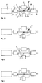
- an engine 1, a starting catalytic converter 2, an adsorber 3 and a main catalytic converter 4 are connected to one another by means of a pipeline system.
- a first pipe part 5 extends between the output of the engine 1 and the input of the starting catalytic converter 2
- a second pipe part 6 extends between the output of the starting catalytic converter 2 and the input of the main catalytic converter 4
- a third pipe part 7 leads away from the main catalytic converter 4 , for example towards an exhaust.
- the adsorber 3 is arranged in a bypass line 8, which opens out from the above-mentioned pipe part 6 on the input side with respect to the adsorber 3, and on the output side with respect to the adsorber 3 again opens into the pipe part 6.
- an exhaust gas flap 9 or 10 to be opened and closed is provided in the bypass line in front of and behind the adsorber 3, and in the pipe part 6, which extends between the starting catalyst 2 and the main catalyst 4, is on at the point which is located between the mouth of the bypass line 8 and the mouth of the bypass line 8, a further exhaust flap 11 to be opened and closed is arranged.
- a sensor 18 is arranged, which detects the temperature of the exhaust gas stream or the gas composition of the exhaust gas stream at least with regard to one of the exhaust gas components HC, CO and NOX or a combination thereof.
- the sensor 18 is acted upon by the exhaust gas flow led through the adsorber 3, the exhaust gas flow emerging from the starting catalytic converter 2 or a mixture thereof.
- the lambda probe 19 is usually arranged downstream of the starting catalytic converter 2; however, it can also be arranged upstream of the starting catalytic converter 2 if the thermal conditions allow it.
- a control unit 20 which receives the signals from the sensor 18 and the lambda probe 19 and determines from this which of the exhaust flaps 9, 10 or 11 is to be opened or closed.
- FIGS. 2 to 4 represent sub-variants of the embodiment according to FIG. 1.
- only the exhaust flaps 10 and 11 are provided
- according to FIG. 3 only the exhaust flaps 9 and 11 are provided
- the minimum solution is according to only the exhaust flap 11 is provided in the embodiment shown in FIG.
- FIG. 5 A further embodiment is shown in FIG. 5, the same components being identified with the same reference numerals as in FIG. 1.
- the bypass line 8 does not branch off from the pipe part 6 extending between the starting catalytic converter 2 and the main catalytic converter 4, as shown in FIG. 1, but already opens out from the pipe section 6 extending between the output of the engine and the input of the starting catalytic converter 2 Pipe part 5 from and in front of the starting catalytic converter 2. Therefore, an exhaust flap to be opened and closed is not arranged in the pipeline part 6, as in FIG. 1, but rather in the pipeline part 5 between the mouth and confluence point of the bypass line 8 with respect to the pipeline part 5.
- This exhaust flap is designated in the drawing with the reference number 12.
- the exhaust flaps 9 and 10 can also optionally be omitted or provided in the exemplary embodiment according to FIG.
- FIG. 6 A further embodiment is shown in FIG. 6, wherein, like in FIGS. 1 and 5, the same elements are designated by the same reference numerals.
- a connecting line 13 is additionally provided in the embodiment according to FIG. 6, which connects the pipe part 5 on the outlet side to the bypass line 8 with respect to the adsorber, and 2 further exhaust flaps 14 and 15 are provided, one of which is an exhaust flap 14 is arranged directly in front of the starting catalytic converter behind the branching point of the branching line 13 in the pipe part 5, and the other exhaust flap 15 in the bypass line 8 is arranged on the output side with respect to the adsorber 3 behind the junction point of the branching line 13 in the bypass line 8.
- the bypass line 8 opens out of the pipe part 5 and into the pipe part 6.
- FIG. 7 A last embodiment is shown in FIG. 7, the same elements as in FIGS. 1, 5 and 6 being designated with the same reference numerals.
- the adsorber is in the bypass line between a connecting line 16, which opens out from the pipe part 6 behind the starting catalytic converter 2 and opens into the bypass line 8 with respect to the adsorber 3 on the inlet side, and that on the outlet side of the adsorber again opening into the pipeline part 6 Bypass line 8 arranged.
- an exhaust flap 17 is arranged in the bypass line 8 in front of the point at which the connecting line 16 opens into the bypass line 8.
- This starting catalytic converter 2 has a central channel which is provided with an exhaust gas flap and is surrounded by a bypass annular gap. When the exhaust flap is closed, the exhaust gas flow flows through the annular gap, whereas when the exhaust flap is open, the flow through the central channel is almost exclusively, since its flow resistance is significantly smaller than that of the annular gap.
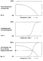
- FIGS. 8 to 10 show the adsorption characteristics of the adsorber and the conversion characteristics of the starting catalyst.
- the adsorber has a high storage rate at the start of operation, i.e. it can store a large volume of pollutants per unit of time. As the time period progresses, the adsorber fills up and also assumes a higher temperature, which reduces the volume that can be stored per unit of time.
- the starting catalytic converter conversion rate at the start of operation is low and only increases relatively steeply after a certain dead time or from a certain temperature.
- the design of the starting catalyst and the adsorber is chosen so that the intersection of the two curves is such that it is as high as possible between 0 and 100%, which means that it is then ensured that the adsorber still guarantees a high adsorber storage volume rate while the exhaust gas volume rate converted by the starting catalytic converter is already relatively high.
- the exhaust flap 11 is initially closed in the exemplary embodiment according to FIG. 1, as a result of which the exhaust gas flow from the engine via the pipeline part 5 through the starting catalytic converter 2 into the bypass line 8 through the adsorber 3 and back again into the pipeline part 6 and finally through the main catalyst 4 and by means of the pipe part 7 flows into the exhaust.
- the exhaust flaps 9 and 10 are closed.
- the exhaust gas flaps 9 and 10 are closed and the exhaust gas flap 11 is opened, after which the main catalytic converter 4 Has the opportunity to heat up to its light-off temperature.
- the exhaust flap 11 is closed again and the exhaust flaps 9 and 10 are opened again, whereby the adsorber 3 is flushed by passing hot exhaust gas through it, which leads to the desorption of the pollutants initially adsorbed in the adsorber.
- These are then passed through the main catalytic converter 4, where the exhaust gas stream, which is additionally enriched with the desorbed exhaust gas components, can be converted in the main catalytic converter 4.
- the exhaust flaps 9 and 10 are closed again, as a result of which the adsorber 3 is completely isolated from the exhaust gas stream; and after later switching off and cooling the engine and the starting catalyst 2 and the main catalyst 4 is ready for a new operation.
- the exhaust flaps 9 and 10 are open at the start of operation and the exhaust flap 12 is closed, as a result of which the entire exhaust gas flow from the engine 1 via the pipeline part 5 by means of the bypass line 8 through the adsorber 3 back into the pipeline part 5 and then through the starting catalyst 2 and by means of the pipeline part 6 through the main catalyst 4 and by means of the pipeline part 7 into the exhaust, and so an adsorption of exhaust gas volume can take place in the adsorber 3.
- the exhaust gas flap 12 is opened and the exhaust gas flaps 9 and 10 are closed, as a result of which the exhaust gas flow directly from the engine 1 by means of the pipe part 5 through the starting catalytic converter 2 and by means of the pipe part 6 through the main catalytic converter 4 and from there is conveyed from the pipe part 7 to the exhaust.
- the exhaust gas flap 12 is closed again and the exhaust gas flaps 9 and 10 become again opened, whereby the adsorber 3 can be rinsed.
- the pollutants desorbed in this way can then react further both in the starting catalytic converter 2 and in the main catalytic converter 4.
- the exhaust flaps 12 and 15 are first closed at the start of operation, and the exhaust flaps 9, 10 and 14 are opened, as a result of which the exhaust gas flow first flows through the adsorber 3, then through the starting catalyst 2 and finally through the main catalyst 4.
- the exhaust gas flap 12 is opened and the exhaust gas flaps 9 and 10 are closed, as a result of which the exhaust gas flow initially flows only from the engine directly through the starting catalytic converter 2 and then through the main catalytic converter 4.
- the exhaust gas flap 12 is closed and the exhaust gas flaps 9 and 10 are opened, as a result of which the exhaust gas components desorbed from the adsorber can be converted both in the starting catalytic converter and in the main catalytic converter.
- the desorbed exhaust gas components can also be converted only in the main catalytic converter by closing the exhaust gas flap 14 and opening the exhaust gas flap 15.
- the exhaust flaps 9, 10, 14 can finally be closed and the exhaust flaps 12 and 14 can be opened, whereby the exhaust gas flow from the engine 1 via the pipeline part 5 through the connecting line 13 through the bypass line 8 and the pipeline part 6 directly into the main catalytic converter 4 and out of it via the pipe part 7 into the exhaust pipe.
- the flaps 8, 9 and 14 can also be closed and the flaps 12 and 15 can be opened, as a result of which the exhaust gas flow then directly from Engine 1 can flow through the main catalyst 4 and from there through the exhaust into the open.
- FIG. 7 A last embodiment is shown in FIG. 7, with exhaust flaps 11 and 17 initially closed and exhaust flaps 14, 9 and 10 open at the start of operation, as a result of which the exhaust gas flow from the engine 1 through the pipe part 5 and subsequently through the starting catalytic converter 2 by means of the connecting line 16 and continues to flow by means of the bypass line 8 through the adsorber 3 back into the pipe part 6 and through the main catalyst 4.
- the exhaust flaps 9 and 10 are closed in addition to the exhaust flap 17 and the exhaust flaps 14 and 11 are opened, so that the exhaust gas flow from the engine 1 is direct can be passed through the starting catalyst 2 and then through the main catalyst 4.
- the exhaust gas flap 11 is closed again and the exhaust gas flaps 9 and 10 are opened, as a result of which the exhaust gas flow can initially flow through the starting catalytic converter 2 via the connecting line 16 through adsorber 3 into the main catalytic converter 4 and the adsorber 3 being rinsed or discharged.
- the exhaust flaps 9 and 10 are closed again and the exhaust flap 11 is opened, and the exhaust gas flow can flow from the engine directly through the starting catalytic converter 2 and then through the main catalytic converter 4.
- the exhaust flap 14 can optionally be closed and the exhaust flap 17 opened, the previously opened exhaust flap 11 remaining in its open state and the previously closed exhaust flaps 9 and 10 in their closed state.
- the exhaust gas flow from the engine 1 can flow through the connecting line 16 by means of the bypass line 8 and directly through the main catalytic converter 4 by means of the pipe part 6, as a result of which the starting catalytic converter is completely switched off during long-distance operation of the vehicle and is thus protected becomes.
- the control of the exhaust flaps 10, 11 will now be explained with reference to the embodiment shown in FIG. 2.
- the exhaust gas flap 11 is closed and the exhaust gas flap 10 is opened, so that the exhaust gas flow is passed completely through the adsorber 3.
- the sensor 18 detects the exhaust gas flow on the outlet side of the adsorber 3. If the probe 18 is suitable for detecting the temperature of the exhaust gas flow, it is determined whether the temperature of the exhaust gas flow exceeds a limit value. This limit value is chosen such that desorption begins in adsorber 3 when the limit value is reached. With this procedure, the knowledge is used that the temperature of the exhaust gas stream after flowing through the adsorber 3 allows conclusions to be drawn about the temperature of the adsorber 3 itself.
- the point at which desorption starts in the adsorber 3 is not solely dependent on the temperature of the adsorber 3, but also on the HC concentration of the exhaust gas stream entering the adsorber 3. Therefore, with the above-described procedure based on temperature detection, the point in time at which the adsorber 3 can no longer be accommodated can only be approximately determined. A significantly more precise determination of this point in time is possible if the sensor 18 determines the gas composition, in particular the HC content, in the exhaust gas stream downstream of the adsorber 3.
- a lambda probe can be used for this purpose, which is surrounded by a catalytically active layer.
- the catalytic layer is chosen so that here a reaction of HC and O 2 takes place.
- the adsorber 3 As long as there is no HC in the exhaust gas stream, ie the adsorber 3 is able to absorb the HC in the exhaust gas stream, the O 2 in the exhaust gas stream can pass the catalytic layer to the actual lambda probe and generate a corresponding signal here.
- Is in the exhaust gas stream downstream of the Adsorbers 3 contain HC, ie the adsorber 3 is saturated, so that HC penetrates through the adsorber 3, react in the catalytic layer HC and O 2 , so that no further O 2 can reach the actual lambda probe and in turn generates a corresponding signal .
- the latter including the catalytic layer, must be heated in a known manner.
- the control unit 20 recognizes from the signal supplied by the sensor 18 that the limit value for the temperature of the exhaust gas flow has been exceeded and / or that HC is contained in the exhaust gas flow, i.e. If the saturation limit of the adsorber 3 has been reached, the control unit 20 closes the exhaust flap 10 and simultaneously opens the exhaust flap 11. With the above-described procedures, it is possible to control the exhaust gas flow exactly as long when the engine 1 is cold started by controlling the exhaust flaps 10, 11 to conduct over the adsorber 3, as it is able to absorb HC.
- the storage capacity of the adsorber is exploited in the best possible way, regardless of the ambient conditions, on the other hand, care is taken to ensure that the exhaust gas flow is no longer sensibly applied to the adsorber 3 and that the exhaust gas flow can be passed directly to the main catalytic converter 4 as early as possible, so that it quickly reaches its activation temperature and ensures effective exhaust gas cleaning.
- the rinsing of the adsorber 3 after reaching the light-off temperature is also controlled with the aid of the sensor 18.
- the sensor 18 is designed as a temperature sensor, the duration of the rinsing process is determined depending on the temperature signal supplied by the sensor 18. For this purpose, values for the rinsing time are stored in a map, not shown, depending on the signal from the sensor. A more precise control is also possible here if the gas composition is determined with the sensor 18. In this case, the exhaust gas flow by controlling the exhaust flaps 10, 11 for so long passed through the adsorber 3 until the sensor 18 in the exhaust gas stream downstream of the adsorber 3 can no longer determine any proportions of HC in the exhaust gas stream.
- the signal of the lambda probe 19, which is arranged upstream of the adsorber 3, is also used. Since the lambda probe 19, if it is arranged behind the starting catalytic converter 2, detects the gas composition directly in front of the adsorber 3, it is now possible to compare the signal from the sensor 18 with the signal from the lambda probe 19. This comparison is particularly easy to carry out if the sensor 18 and the lambda probe 19 are identical parts. In this case, the adsorber 3 is flushed by opening the exhaust flap 10 and closing the exhaust flap 11 until the signals from the sensor 18 and the lambda probe 19 are the same. At this time, the exhaust gas flow flows through the adsorber 3 without a change in the composition of the exhaust gas flow taking place in the adsorber 3 and the adsorber 3 is thus completely desorbed.
- the adsorber 3 i.e. with the exhaust flap 10 closed and the exhaust flap 11 open, the difference between the signals from the sensor 18 and the lambda probe 19 can be formed and stored. The adsorber 3 is then rinsed until the difference in the signals again reaches the previously stored value.
- a characteristic temperature of the engine for example the cooling water or oil temperature, is used to decide whether the adsorber 3 is switched on when the engine 1 starts. If the adsorber 3 is switched on or if it was not completely discharged in a previous operating phase of the engine 1, the adsorber 3 is rinsed according to the procedure outlined above as soon as it is ensured that the main catalyst 4 is its Activation temperature has reached.
- the main catalytic converter 4 reaches its starting temperature significantly faster, so that the total emissions during the starting process are significantly reduced even without the starting catalytic converter 2 are.
- the arrangement of the sensor 18 directly upstream of the main catalytic converter 4 is only absolutely necessary if the control device controls the exhaust gas flaps 9, 10 and 11 with the aid of the previously described comparison of the signals supplied by the sensor 18 and the lambda probe 19. Otherwise, the sensor 18 can also be arranged at any point downstream of the adsorber 3.
- Control of the exhaust flaps 9, 10 and 11 described can be used in the same way for controlling the exhaust flaps 9, 10, 11, 12, 13, 14, 15 and 17 in the embodiments according to FIGS. 1 and 3 to 7, insofar as they are used to apply the exhaust gas flow to the adsorber 3.
Landscapes
- Engineering & Computer Science (AREA)
- Chemical & Material Sciences (AREA)
- Combustion & Propulsion (AREA)
- Mechanical Engineering (AREA)
- General Engineering & Computer Science (AREA)
- Chemical Kinetics & Catalysis (AREA)
- Exhaust Gas After Treatment (AREA)
- Measuring Oxygen Concentration In Cells (AREA)
- Combined Controls Of Internal Combustion Engines (AREA)
Abstract
Description
Die Erfindung betrifft ein Verfahren zur Abgasreinigung bei Kraftfahrzeugen nach dem Oberbegriff des Patentanspruchs 1, sowie eine Vorrichtung zur Abgasreinigung bei Kraftfahrzeugen nach dem Oberbegriff des Patentanspruchs 8.The invention relates to a method for exhaust gas purification in motor vehicles according to the preamble of patent claim 1, and to a device for exhaust gas purification in motor vehicles according to the preamble of
Einen Ansatzpunkt für eine weitere Reduzierung der Schadstoffemissionen von mit einem Katalysator versehenen Kraftfahrzeugen bietet die Warmlaufphase des katalytischen Systems, weil ausgehend vom kalten Zustand des Kraftfahrzeugs und damit des katalytischen Systems von dem Kraftfahrzeug ungereinigtes Rohabgas emittiert wird. Dadurch, daß das katalytische System erst ab einer gewissen Anspringtemperatur, auch Light-off-Temperatur genannt, eine wirksame Abgasreinigung durchführen kann, handelt es sich also bei den bekannten katalytischen Systemen um eine systembedingte Schwäche, die zur Folge hat, daß das katalytische System insbesondere bei Kaltstart des Fahrzeugmotors, d.h. der das Kraftfahrzeug antreibenden Brennkraftmaschine weitgehend unwirksam ist. Um hier Abhilfe zu schaffen, war es aus dem Stand der Technik beispielsweise bekannt, den Katalysator von außen vorzuheizen, damit dieser möglichst schnell seine Anspringtemperatur erreicht. Unter der Anspringtemperatur versteht man diejenige Temperatur des Katalysators, bei welcher dieser eine nicht unwesentliche Konvertierungsrate verwirklicht, die beispielsweise bei wenigstens 30 bis 50 % liegt.The warm-up phase of the catalytic system offers a starting point for a further reduction in the pollutant emissions from motor vehicles provided with a catalytic converter, because crude exhaust gas which has not been cleaned by the motor vehicle is emitted starting from the cold state of the motor vehicle and thus the catalytic system. Because the catalytic system can only carry out effective exhaust gas cleaning from a certain light-off temperature, the known catalytic systems are a system-related weakness, which means that the catalytic system in particular when the vehicle engine is cold started, ie the internal combustion engine driving the motor vehicle is largely ineffective. In order to remedy this, it was known from the prior art, for example, to preheat the catalyst from the outside so that it quickly reaches its light-off temperature. The light-off temperature is the temperature of the catalyst at which the catalyst achieves a not insignificant conversion rate, which is, for example, at least 30 to 50%.
Als ein anderer Ansatz war es aus dem Stand der Technik bekannt, Adsorber einzusetzen, welche in der Lage sind, Abgaskomponenten bei niedrigen Temperaturen zu speichern (zu adsorbieren) und bei höheren Temperaturen wieder abzugeben (zu desorbieren). Dabei ist die Adsorptionsfähigkeit umso größer, je niedriger die Gas- und Adsorbertemperatur ist. Das bedeutet, daß in der Start- und Warmlaufphase, wenn das katalytische System noch unwirksam ist, von dem dem katalytischen System vorgeschalteten Adsorber bestimmte Abgaskomponenten adsorbiert und erst dann wieder abgegeben werden, wenn das katalytische System seine Betriebstemperatur erreicht hat. Auf diese Weise kann der Adsorber eine ideale Ergänzung des katalytischen Systems darstellen.As another approach, it was known from the prior art to use adsorbers which are capable of storing (adsorbing) exhaust gas components at low temperatures and releasing (desorbing) them again at higher temperatures. The lower the gas and adsorber temperature, the greater the adsorption capacity. This means that in the start-up and warm-up phase, when the catalytic system is still inactive, that of the catalytic system Upstream adsorber adsorbed certain exhaust gas components and are only released again when the catalytic system has reached its operating temperature. In this way, the adsorber can be an ideal addition to the catalytic system.
Jedoch ist es nach dem Stand der Technik bisher nicht gelungen, ein optimales Zusammenwirken zwischen dem Adsorber und dem katalytischen System zu verwirklichen, weil mit steigender Temperatur des Adsorbers bzw. mit steigender Abgastemperatur die Adsorptionsfähigkeit des Adsorbers zunächst sinkt und dann sogar die Desorption des Adsorbers beginnt, bevor das nachfolgende katalytische System seine Anspringtemperatur erreicht hat. Die nicht adsorbierten oder sogar desorbierten Abgaskomponenten durchströmen dann ohne Nachreaktion das katalytische System. Da der Adsorber nur bei vergleichsweise niedrigen Temperaturen wirksam ist, der Katalysator aber nur bei vergleichsweise hohen Temperaturen, ergibt sich somit systembedingt eine Zwischenzeitspanne, in welcher weder der Adsorber, noch der Katalysator ausreichend wirksam sind, oder im noch schlechteren Fall der Adsorber sogar selbst desorbiert, während der Katalysator noch nicht wirksam ist, was im Extremfall zur vollkommenen Sinnlosigkeit des Adsorbers führen kann.However, according to the prior art it has not been possible to achieve an optimal interaction between the adsorber and the catalytic system, because with increasing temperature of the adsorber or with increasing exhaust gas temperature, the adsorptive capacity of the adsorber initially drops and then even the desorption of the adsorber begins before the subsequent catalytic system has reached its light-off temperature. The non-adsorbed or even desorbed exhaust gas components then flow through the catalytic system without subsequent reaction. Since the adsorber is only effective at comparatively low temperatures, but the catalyst only at comparatively high temperatures, there is an interim period in which the adsorber and the catalyst are not sufficiently effective, or in the worse case the adsorber even desorbs itself , while the catalyst is not yet effective, which in extreme cases can lead to the complete senselessness of the adsorber.
Der Erfindung liegt die Aufgabe zugrunde, ein Verfahren und eine Vorrichtung der eingangs erwähnten Art zur Abgasreinigung bei Kraftfahrzeugen zu schaffen, wobei ein optimales Zusammenwirken zwischen dem Adsorber und dem katalytischen System derart stattfindet, daß in sämtlichen Betriebsphasen des Kraftfahrzeugs eine Abgasreinigung stattfindet.The invention has for its object to provide a method and an apparatus of the type mentioned above for exhaust gas purification in motor vehicles, an optimal interaction between the adsorber and the catalytic system taking place in such a way that exhaust gas purification takes place in all operating phases of the motor vehicle.
Dies wird gemäß dem erfindungsgemäßen Verfahren dadurch erreicht, daß die Gaszusammensetzung oder die Temperatur oder eine Kombination hieraus stromab des Adsorbers ermittelt wird, und daß abhängig von der ermittelten Gaszusammensetzung oder der Temperatur oder einer Kombination hieraus der Abgasstrom durch den Adsorber geführt wird.This is achieved in accordance with the method according to the invention in that the gas composition or the temperature or a combination thereof is determined downstream of the adsorber, and that the exhaust gas stream is passed through the adsorber depending on the gas composition or the temperature or a combination thereof.
Mittels der erfindungsgemäßen Vorrichtung wird dies dadurch erreicht, daß stromab des Adsorbers ein Sensor zur Ermittlung der Gaszusammensetzung oder der Gastemperatur oder eimer Kombination hieraus vorgesehen ist, und ein Steuergerät abhängig vom Signal des Sensors durch Ansteuerung der Klappen den Abgasstrom durch den Adsorber führt.This is achieved by means of the device according to the invention in that a sensor for determining the gas composition or the gas temperature or a combination thereof is provided downstream of the adsorber, and a control device guides the exhaust gas flow through the adsorber depending on the signal of the sensor by actuating the flaps.
Vorteilhafte Weiterbildungen der Erfindung sind in den Unteransprüchen beschrieben.Advantageous developments of the invention are described in the subclaims.
Erfindungsgemäß wurde durch die Anordnung des Adsorbers in einem Bypaß und die Steuerung mittels der Abgasklappen, sowie mittels des nahe an dem Motorausgang angeordneten und damit relativ schnell aufheizenden Startkatalysators erstmals das ebenfalls erfindungsgemäße Verfahren ermöglicht, wonach das katalytische System mit dem Adsorber so zusammenwirkt, daß der Startkatalysator seine Anspringtemperatur bereits erreicht, während der Adsorber noch eine hohe Wirksamkeit aufweist, aber umgekehrt kein Spülvorgang stattfindet, bevor nicht auch der weiter hinten im Abgasstrom befindliche Hauptkatalysator seine Anspringtemperatur erreicht hat.According to the invention, the arrangement of the adsorber in a bypass and the control by means of the exhaust flaps, as well as by means of the starting catalytic converter arranged close to the engine outlet and thus heating up relatively quickly, for the first time enabled the process according to the invention, after which the catalytic system interacts with the adsorber in such a way that the Starting catalytic converter has already reached its light-off temperature while the adsorber is still highly effective, but conversely no flushing process takes place until the main catalytic converter located further back in the exhaust gas stream has also reached its light-off temperature.
Gemäß einer vorteilhaften Weiterbildung der Erfindung durchströmt nach Erreichen der Anspringtemperatur des Hauptkatalysators der Abgasstrom zum Spülen bzw. Entladen des Adsorbers in Folge zuerst den Startkatalysator, dann den Adsorber und dann den Hauptkatalysator. Analog dazu kann nach Erreichen der Anspringtemperatur des Hauptkatalysators der Abgasstrom zum Spülen bzw. Entladen des Adsorbers in Folge zuerst den Startkatalysator durchströmen, dann in zwei Teilströme geteilt werden, wovon einer der beiden Teilströme durch den Adsorber strömt und sich beide Teilströme hinter dem Adsorber wieder vereinigen, um dann gemeinsam durch den Hauptkatalysator zu strömen.According to an advantageous development of the invention, after reaching the light-off temperature of the main catalytic converter, the exhaust gas flow for purging or discharging the adsorber flows first through the starting catalytic converter, then through the adsorber and then through the main catalytic converter. Similarly, after the start-up temperature of the main catalytic converter has been reached, the exhaust gas stream for purging or discharging the adsorber can first flow through the starting catalytic converter, then be divided into two sub-streams, of which one of the two sub-streams flows through the adsorber and both sub-streams unite behind the adsorber to then flow together through the main catalytic converter.
Dies kann vorteilhaft mittels einer erfindungsgemäß weitergebildeten Vorrichtung verwirklicht werden, bei welcher die Bypaßleitung hinter dem Startkatalysator von demjenigen Rohrleitungsteil, welcher den Ausgang des Startkatalysators mit dem Eingang des Hauptkatalysators verbindet, abzweigt, wobei die Bypaßleitung eingangsseitig mit dem Eingang bzw. ausgangsseitig mit dem Ausgang des Adsorbers verbunden ist, wobei der ausgangsseitige Teil der Bypaßleitung wieder in denjenigen Rohrleitungsteil einmündet, welcher den Ausgang des Startkatalysators mit dem Eingang des Hauptkatalysators verbindet.This can advantageously be achieved by means of a device developed according to the invention, in which the bypass line behind the starting catalytic converter is one Pipe part, which connects the outlet of the starting catalytic converter to the inlet of the main catalytic converter, branches off, the bypass pipe being connected on the inlet side to the inlet and on the outlet side to the outlet of the adsorber, the outlet-side part of the bypass pipe re-opening into the pipe section which opens the outlet of the Starting catalyst connects to the input of the main catalyst.
Das vorgenannte, erfindungsgemäß weitergebildete Verfahren bzw. die Weiterbildung der Vorrichtung zum Durchführen dieses Verfahrens bieten den Vorteil, daß der Startkatalysator so nahe wie möglich an den Motorausgang gelegt werden kann, sich dadurch schnell aufheizt und dabei den Abgasstrom abkühlt, welcher nachfolgend durch den im Bypaß angeordneten Adsorber strömt. Dadurch wird einerseits der Startkatalysator schnell aufgeheizt und damit schnell wirksam, während andererseits der Adsorber so lange wie möglich kühl gehalten wird und damit ebenfalls relativ lange seine Wirksamkeit beibehält.The above-mentioned, further developed method according to the invention and the development of the device for performing this method offer the advantage that the starting catalyst can be placed as close as possible to the engine outlet, thereby heating up quickly and thereby cooling the exhaust gas stream, which is subsequently bypassed by the arranged adsorber flows. In this way, on the one hand, the starting catalytic converter is quickly heated up and thus quickly effective, while on the other hand the adsorber is kept cool for as long as possible and thus also remains effective for a relatively long time.
Gemäß einer erfindungsgemäßen Weiterbildung kann nach hinreichender Spülung des Adsorbers der Abgasstrom aus dem Startkatalysator wieder direkt in den Hauptkatalysator geleitet werden. In anderen Worten, der Abgasstrom durchströmt nicht mehr länger den Adsorber, wodurch dieser nach dem Spülen bzw. nach der Desorption, vor Verunreinigungen sowie thermischer Belastung durch den Abgasstrom bewahrt wird. Auch lassen sich so die Strömungsverhältnisse für den eingeschwungenen Zustand oder Dauerbetrieb optimal einstellen. Hierzu kann vorteilhaft in dem Rohrleitungsteil zwischen dem Startkatalysator und dem Hauptkatalysator eine zu öffnende und schließende Abgasklappe vorgesehen sein, und es kann für die vollständige Ausschaltung des Adsorbers in der Bypaßleitung vor oder vor und hinter dem Adsorber jeweils eine zu öffnende und zu schließende Abgasklappe vorgesehen sein.According to a further development according to the invention, after the adsorber has been adequately flushed, the exhaust gas stream from the starting catalytic converter can again be passed directly into the main catalytic converter. In other words, the exhaust gas flow no longer flows through the adsorber, as a result of which it is protected from contamination and thermal stress from the exhaust gas flow after flushing or after desorption. The flow conditions for the steady state or continuous operation can also be optimally adjusted. For this purpose, an exhaust flap that can be opened and closed can advantageously be provided in the pipeline part between the starting catalytic converter and the main catalytic converter, and an exhaust flap that can be opened and closed can be provided in front of or in front of and behind the adsorber for the complete deactivation of the adsorber .
Eine weitere vorteilhafte Weiterbildung des erfindungsgemäßen Verfahrens sieht nach hinreichender Spülung des Adsorbers vor, daß der Abgasstrom für den Dauerbetrieb aus dem Motor direkt durch den Hauptkatalysator geleitet wird. Dies bringt den Vorteil mit sich, daß der Startkatalysator einerseits nur für relativ kurzzeitigen Betrieb ausgelegt werden muß, und andererseits an dem Startkatalysator solche Strömungsverhältnisse eingestellt werden können, daß sich dieser besonders schnell aufheizt, ohne dadurch den Dauerbetrieb negativ zu beeinträchtigen.A further advantageous development of the method according to the invention provides, after the adsorber has been adequately flushed, that the exhaust gas flow for continuous operation from the engine is passed directly through the main catalytic converter. This has the advantage that the starting catalytic converter on the one hand only has to be designed for relatively short-term operation, and on the other hand such flow conditions can be set on the starting catalytic converter that it heats up particularly quickly without thereby adversely affecting continuous operation.
Dies kann beispielsweise durch eine erfindungsgemäße Vorrichtung verwirklicht werden, bei welcher die Bypaßleitung vor dem Startkatalysator abzweigt, wobei die Bypaßleitung eingangsseitig mit dem Eingang bzw. ausgangsseitig mit dem Ausgang des Adsorbers verbunden ist, wobei der ausgangsseitige Teil der Bypaßleitung in denjenigen Rohrleitungsteil einmündet, welcher den Ausgang des Startkatalysators mit dem Eingang des Hauptkatalysators verbindet, und zusätzlich hinter dem Startkatalysator von demjenigen Rohrleitungsteil, welcher den Ausgang des Startkatalysators mit dem Eingang des Hauptkatalysators verbindet, eine Verbindungsleitung abzweigt, welche mit der Bypaßleitung eingangsseitig bezogen auf den Adsorber verbunden ist.This can be achieved, for example, by a device according to the invention, in which the bypass line branches off in front of the starting catalytic converter, the bypass line being connected on the inlet side to the inlet and on the outlet side to the outlet of the adsorber, the outlet-side part of the bypass line opening into the pipe section which opens the Connects the output of the starting catalytic converter to the input of the main catalytic converter, and in addition, behind the starting catalytic converter, branches off from the pipe part which connects the output of the starting catalytic converter to the input of the main catalytic converter, a connecting line which is connected to the bypass line on the input side with respect to the adsorber.
Gemäß einer anderen vorteilhaften Weiterbildung der Erfindung ist die erfindungsgemäße Vorrichtung derart ausgebildet, daß die Bypaßleitung vor dem Startkatalysator von demjenigen Rohrleitungsteil, welcher den Ausgang des Motors mit dem Eingang des Startkatalysators verbindet, abzweigt, wobei die Bypaßleitung eingangsseitig mit dem Eingang bzw. ausgangsseitig mit dem Ausgang des Adsorbers verbunden ist, wobei der ausgangsseitige Teil der Bypaßleitung wieder in denjenigen Rohrleitungsteil einmündet, welcher den Ausgang des Motors mit dem Eingang des Startkatalysators verbindet.According to another advantageous development of the invention, the device according to the invention is designed in such a way that the bypass line in front of the starting catalytic converter branches off from the pipe part which connects the output of the engine to the input of the starting catalytic converter, the bypass line on the input side with the input or on the output side with the The output of the adsorber is connected, the outlet-side part of the bypass line again opening into the pipe part which connects the output of the engine to the inlet of the starting catalytic converter.
Dabei kann vorteilhaft in demjenigen Rohrleitungsteil, welcher dem Motor mit dem Eingang des Startkatalysators verbindet, hinter der Abzweigungsstelle für die Bypaßleitung eine zu öffnende und zu schließende Abgasklappe vorgesehen sein. Dabei können sogar der Startkatalysator und der Hauptkatalysator zu einem einzigen Bauteil zusammengefaßt werden, sodaß diese zusammen einen einzigen Katalysator ausbilden, was konstruktiv vorteilhaft zu verwirklichen ist. Etwas nachteilig kann es sich dabei allenfalls auswirken, daß der Adsorber näher an dem Motor angeordnet ist als der Startkatalysator und damit früher aufgeheizt wird, während der Startkatalysator langsamer aufgeheizt wird.In this case, an exhaust gas flap that can be opened and closed can advantageously be provided in the pipe part that connects the engine to the inlet of the starting catalytic converter, behind the branching point for the bypass line. Here Even the starting catalytic converter and the main catalytic converter can be combined into a single component, so that they form a single catalytic converter together, which can be implemented in a constructively advantageous manner. At most, it can have a somewhat disadvantageous effect that the adsorber is arranged closer to the engine than the starting catalytic converter and is therefore heated up earlier, while the starting catalytic converter is heated up more slowly.
Vorteilhaft kann derjenige Zeitpunkt, in welchem der Startkatalysator seine Anspringtemperatur erreicht hat, oder derjenige Zeitpunkt, in welchem der Adsorber seine hohe Adsorptionsfähigkeit verliert, durch Sensoren und/oder ein Rechenmodell ermittelt werden.The point in time at which the starting catalyst has reached its light-off temperature or the point in time at which the adsorber loses its high adsorption capacity can advantageously be determined by sensors and / or a computing model.
Entsprechend kann in vorteilhafter Weise derjenige Zeitpunkt, ab welchem der Abgasstrom zum Spülen bzw. Entladen vollständig oder teilweise durch den Adsorber geführt wird, und der derjenige Zeitpunkt, ab welchem der Abgasstrom nach beendigtem Spülvorgang nicht mehr länger durch den Adsorber geführt wird, durch Sensoren und/oder ein Rechenmodell ermittelt werden.Accordingly, the point in time from which the exhaust gas flow for purging or unloading is passed completely or partially through the adsorber, and the point in time from which the exhaust gas flow is no longer passed through the adsorber after the purging process has ended, by sensors and / or a calculation model can be determined.
Als vorteilhaft hat sich weiter erwiesen, als Sensoren Temperatursensoren und/oder Abgassensoren oder einen kombinierten Einsatz davon vorzusehen, auch in Kombination mit Rechenmodellen.It has also proven to be advantageous to provide temperature sensors and / or exhaust gas sensors or a combined use thereof as sensors, also in combination with computing models.
Als Abgassensoren können vorteilhaft solche verwendet werden, welche die Konzentrationen von HC, CO und NOx erfassen, oder es kann ein Sensor verwendet werden, welcher zumindest zwei Funktionen kombiniert, nämlich den "Lambda"-Wert und/oder die Abgastemperatur und/oder die Konzentrationen der Abgaskomponenten erfaßt. Die Erfindung wird nachfolgend anhand von bevorzugten Ausführungsbeispielen unter Bezugnahme auf die Zeichnung näher erläutert. In der Zeichnung zeigen:
- Figuren 1 bis 4 vier Untervarianten eines ersten Ausführungsbeispiels in schematischer Darstellung;
Figur 5 ein zweites Ausführungsbeispiel in schematischer Darstellung;Figur 6 ein drittes Ausführungsbeispiel in schematischer Darstellung;Figur 7 ein viertes Asuführungsbeispiel in schematischer Darstellung;Figur 8 ein Diagramm, welches die Adsorberspeichervolumenrate in Abhängigkeit von der Temperatur bzw. Zeit zeigt;Figur 9 ein Diagramm, welches die Startkatalysator-Umwandlungsrate in Abhängigkeit von der Temperatur bzw. Zeit zeigt; undFigur 10 ein Diagramm, welches die adsorbierte bzw. konvertierte Abgasvolumenrate über der Temperatur bzw. Zeit zeigt.
- Figures 1 to 4 four sub-variants of a first embodiment in a schematic representation;
- Figure 5 shows a second embodiment in a schematic Presentation;
- Figure 6 shows a third embodiment in a schematic representation;
- FIG. 7 shows a fourth exemplary embodiment in a schematic illustration;
- Figure 8 is a diagram showing the adsorber storage volume rate as a function of temperature or time;
- FIG. 9 is a diagram which shows the starting catalyst conversion rate as a function of the temperature or time; and
- Figure 10 is a diagram showing the adsorbed or converted exhaust gas volume rate versus temperature or time.
Wie aus Figur 1 ersichtlich ist, sind ein Motor 1, ein Startkatalysator 2, ein Adsorber 3 und ein Hauptkatalysator 4 mittels eines Rohrleitungssystems miteinander verbunden. Dabei erstreckt sich ein erster Rohrleitungsteil 5 zwischen dem Ausgang des Motors 1 und dem Eingang des Startkatalysators 2, ein zweiter Rohrleitungsteil 6 erstreckt sich zwischen dem Ausgang des Startkatalysators 2 und dem Eingang des Hauptkatalysators 4, und ein dritter Rohrleitungsteil 7 führt von dem Hauptkatalysator 4 weg, beispielsweise zu einem Auspuff hin. Der Adsorber 3 ist in einer Bypaßleitung 8 angeordnet, welche von dem vorgenannten Rohrleitungsteil 6 eingangsseitig bezogen auf den Adsorber 3 ausmündet, und ausgangsseitig bezogen auf den Adsorber 3 wieder in den Rohrleitungsteil 6 einmündet. Bei dem Ausführungsbeispiel nach Figur 1 sind in der Bypaßleitung vor und hinter dem Adsorber 3 jeweils eine zu öffnende und zu schließende Abgasklappe 9 bzw. 10 vorgesehen, und in dem Rohrleitungsteil 6, welcher sich zwischen dem Startkatalysator 2 und dem Hauptkatalysator 4 erstreckt, ist an derjenigen Stelle, welche sich zwischen der Ausmündungsstelle der Bypaßleitung 8 und der Einmündungsstelle der Bypaßleitung 8 befindet, eine weitere zu öffnende und zu schließende Abgasklappe 11 angeordnet.As can be seen from FIG. 1, an engine 1, a starting
Unmittelbar stromauf des Hauptkatalysators 4 ist ein Sensor 18 angeordnet, der die Temperatur des Abgasstromes oder die Gaszusammensetzung des Abgasstromes zumindest hinsichtlich eines der Abgasbestandteile HC, CO und NOX oder eine Kombination hieraus erfaßt. Je nach Stellung der Abgasklappen 9, 1O und 11 ist der Sensor 18 mit dem durch den Adsorber 3 geführten Abgasstrom, dem aus dem Startkatalysator 2 austretenden Abgasstrom oder einer Mischung hieraus beaufschlagt.Immediately upstream of the main
Hinter dem Motor 1 ist zudem eine Lambda-Sonde 19 vorhanden, die für eine Lambda-Regelung für die Gemischaufbereitung des Motors 1 vorgesehen ist. Die Lambda-Sonde 19 ist üblicherweise stromab des Startkatalysators 2 angeordnet; sie kann jedoch auch stromauf des Startkatalysators 2 angeordnet sein, wenn es die thermischen Verhältnisse zulassen.Behind the engine 1 there is also a lambda probe 19 which is provided for lambda control for the mixture preparation of the engine 1. The lambda probe 19 is usually arranged downstream of the starting
Zur Steuerung der Abgasklappen 9, 10 und 11 ist ein Steuergerät 20 vorgesehen, das die Signale des Sensors 18 sowie der Lambda-Sonde 19 erhält und hieraus bestimmt, welche der Abgasklappen 9, 10 oder 11 zu öffnen bzw. zu schließen ist.To control the exhaust flaps 9, 10 and 11, a control unit 20 is provided which receives the signals from the
Die in den Figuren 2 bis 4 dargestellten Ausführungsformen stellen Untervarianten der Ausführungsform nach Figur 1 dar. So sind gemäß der Ausführungsform nach Figur 2 nur die Abgasklappen 10 und 11 vorgesehen, gemäß Figur 3 nur die Abgasklappen 9 und 11 vorgesehen, und als Minimallösung ist gemäß der in Figur 4 dargestellten Ausführungsform nur die Abgasklappe 11 vorgesehen.The embodiments shown in FIGS. 2 to 4 represent sub-variants of the embodiment according to FIG. 1. Thus, according to the embodiment according to FIG. 2, only the exhaust flaps 10 and 11 are provided, according to FIG. 3 only the exhaust flaps 9 and 11 are provided, and the minimum solution is according to only the
Eine weitere Ausführungsform zeigt Figur 5, wobei gleiche Bauteile mit gleichen Bezugszeichen wie in Figur 1 bezeichnet sind. Bei der Ausführungsform nach Figur 5 zweigt die Bypaßleitung 8 jedoch nicht wie gemäß Figur 1 von dem sich zwischen dem Startkatalysator 2 und dem Hauptkatalysator 4 erstreckenden Rohrleitungsteil 6 ab, sondern mündet bereits aus dem sich zwischen dem Ausgang des Motors und dem Eingang des Startkatalysators 2 erstreckenden Rohrleitungsteil 5 aus und vor dem Startkatalysator 2 wieder in diesen ein. Daher ist auch nicht wie nach Figur 1 eine zu öffnende und zu schließende Abgasklappe in dem Rohrleitungsteil 6, sondern in dem Rohrleitungsteil 5 zwischen der Ausmündungs- und Einmündungsstelle der Bypaßleitung 8 bezogen auf den Rohrleitungsteil 5 angeordnet. Diese Abgasklappe ist in der Zeichnung mit dem Bezugszeichen 12 bezeichnet. Analog zu den Ausführungsbeispielen nach den Figuren 2 bis 4 können auch bei dem Ausführungsbeispiel nach Figur 5 die Abgasklappen 9 und 10 wahlweise entfallen oder vorgesehen sein.A further embodiment is shown in FIG. 5, the same components being identified with the same reference numerals as in FIG. 1. In the embodiment according to FIG. 5, however, the
Eine weitere Ausführungsform zeigt Figur 6, wobei ebenso wie bei den Figuren 1 und 5 gleiche Elemente mit gleichen Bezugszeichen bezeichnet sind. Bezogen auf die Ausführungsformen nach Figur 5 ist in der Ausführungsform nach Figur 6 zusätzlich eine Verbindungsleitung 13 vorgesehen, welche den Rohrleitungsteil 5 ausgangsseitig bezogen auf den Adsorber mit der Bypaßleitung 8 verbindet, und es sind 2 weitere Abgasklappen 14 und 15 vorgesehen, wovon die eine Abgasklappe 14 unmittelbar vor dem Startkatalysator hinter der Abzweigungstelle der Abzweigungsleitung 13 in dem Rohrleitungsteil 5 angeordnet ist, und die andere Abgasklappe 15 in der Bypaßleitung 8 ausgangsseitig bezogen auf den Adsorber 3 hinter der Einmündungsstelle der Abzweigungsleitung 13 in der Bypaßleitung 8 angeordnet ist. Die Bypaßleitung 8 mündet insgesamt aus dem Rohrleitungsteil 5 aus und in den Rohrleitungsteil 6 ein.A further embodiment is shown in FIG. 6, wherein, like in FIGS. 1 and 5, the same elements are designated by the same reference numerals. In relation to the embodiments according to FIG. 5, a connecting
Eine letzte Ausführungsform ist in Figur 7 dargestellt, wobei gleiche Elemente ebenso wie in den Figuren 1, 5 und 6 mit gleichen Bezugszeichen bezeichnet sind. Verglichen mit den Ausführungsbeispiel nach Figur 6 ist bei dem Ausführungsbeispiel nach Figur 7 der Adsorber jedoch in der Bypaßleitung zwischen einer Verbindungsleitung 16, welcher aus den Rohrleitungsteil 6 hinter dem Startkatalysator 2 ausmündet und eingangseitig bezogen auf den Adsorber 3 in die Bypaßleitung 8 einmündet, und dem ausgangsseitig des Adsorbers wieder in den Rohrleitungsteil 6 einmündenden Teil der Bypaßleitung 8 angeordnet. Zusätzlich ist eine Abgasklappe 17 in der Bypaßleitung 8 vor derjenigen Stelle angeordnet, an welcher die Verbindungsleitung 16 in die Bypaßleitung 8 einmündet.A last embodiment is shown in FIG. 7, the same elements as in FIGS. 1, 5 and 6 being designated with the same reference numerals. Compared with the exemplary embodiment according to FIG. 6, in the exemplary embodiment according to FIG. 7, however, the adsorber is in the bypass line between a connecting
In den Ausführungsformen nach den Figuren 6 und 7 kann anstelle des im Vergleich mit Fig. 5 zusätzlichen Zweiges der Bypaßleitung 8 und der hinzugefügten Abgasklappen 14, 15, 17 auch eine besondere Ausbildung des Startkatalysators 2 verwendet werden, wie sie beispielsweise aus der DE-A-39 30 380 (= JP-A-3100313) bekannt ist. Dieser Startkatalysator 2 weist einen zentralen, mit einer Abgasklappe versehenen Kanal auf, der von einem Bypaß-Ringspalt umgeben ist. Bei geschlossener Abgasklappe strömt der Abgasstrom durch den Ringspalt, wohingegen bei geöffneter Abgasklappe nahezu ausschließlich der zentrale Kanal durchströmt wird, da dessen Strömungswiderstand deutlich kleiner als der des Ringspaltes ist.In the embodiments according to FIGS. 6 and 7, instead of the additional branch of the
Die Adsorptionscharakteristik des Adsorbers bzw. die Konvertierungscharakteristik des Startkatalysators zeigen die Diagramme gemäß den Figuren 8 bis 10. Wie Figur 8 zeigt, weist der Adsorber bei Betriebsbeginn eine hohe Speicherrate auf, d.h. er kann pro Zeiteinheit ein großes Schadstoffvolumen speichern. Mit fortschreitender Zeitdauer füllt sich der Adsorber und nimmt überdies eine höhere Temperatur an, wodurch sich das pro Zeiteinheit speicherbare Volumen verringert.The diagrams according to FIGS. 8 to 10 show the adsorption characteristics of the adsorber and the conversion characteristics of the starting catalyst. As FIG. 8 shows, the adsorber has a high storage rate at the start of operation, i.e. it can store a large volume of pollutants per unit of time. As the time period progresses, the adsorber fills up and also assumes a higher temperature, which reduces the volume that can be stored per unit of time.
Im Gegensatz dazu ist die Startkatalysator-Umwandlungsrate zu Betriebsbeginn gering und steigt erst nach einer gewissen Totzeit bzw. ab einer gewissen Temperatur relativ steil an.In contrast, the starting catalytic converter conversion rate at the start of operation is low and only increases relatively steeply after a certain dead time or from a certain temperature.
Die Auslegung des Startkatalysators und des Adsorbers ist so gewählt, daß der Schnittpunkt beider Kurven so liegt, daß er möglichst hoch zwischen 0 und 100 % liegt, was bedeutet, daß dann gewährleistet ist, daß der Adsorber immer noch eine hohe Adsorberspeichervolumenrate gewährleistet, während die von dem Startkatalysator konvertierte Abgasvolumenrate auch bereits relativ hoch ist.The design of the starting catalyst and the adsorber is chosen so that the intersection of the two curves is such that it is as high as possible between 0 and 100%, which means that it is then ensured that the adsorber still guarantees a high adsorber storage volume rate while the exhaust gas volume rate converted by the starting catalytic converter is already relatively high.
Die Funktionsweise der Ausführungsformen nach den Figuren 1 bis 7 ist wie folgt:The mode of operation of the embodiments according to FIGS. 1 to 7 is as follows:
Nach dem Anlassen des Motors ist zunächst die Abgasklappe 11 bei dem Ausführungsbeispiel nach Figur 1 geschlossen, wodurch der Abgasstrom von dem Motor über den Rohrleitungsteil 5 durch den Startkatalysator 2 in die Bypaßleitung 8 durch den Adsorber 3 und wieder zurück in den Rohrleitungsteil 6 und schließlich durch den Hauptkatalysator 4 sowie mittels des Rohrleitungsteils 7 in den Auspuff strömt. Dabei sind die Abgasklappen 9 und 10 geschlossen. Nachdem der Startkatalysator seine Anspringtemperatur erreicht hat, bzw. nachdem der Adsorber 3 nur noch eine zu vernachlässigende Wirkung aufgrund der Erwärmung bzw. aufgrund des voll ausgenutzten Speichervolumens hat, werden die Abgasklappen 9 und 10 geschlossen und die Abgasklappe 11 wird geöffnet, wonach der Hauptkatalysator 4 Gelegenheit erhält, sich bis auf seine Anspringtemperatur zu erhitzen. Danach wird die Abgasklappe 11 erneut geschlossen und die Abgasklappen 9 und 10 werden erneut geöffnet, wodurch der Adsorber 3 gespült wird, indem heißes Abgas durch diesen geleitet wird, welches zur Desorption der eingangs in dem Adsorber adsorbierten Schadstoffe führt. Diese werden dann durch den Hauptkatalysator 4 geleitet, wo der Abgasstrom, welcher zusätzlich mit den desorbierten Abgasbestandteilen angereichert ist, in dem Hauptkatalysator 4 konvertiert werden kann.After the engine has been started, the
Nach erfolgter Spülung, wobei derjenige Zeitpunkt, in welchem die Spülung bzw. Desorption beendet ist, durch Abgassensoren oder Rechenmodelle festgestellt werden kann, werden die Abgasklappen 9 und 10 wieder geschlossen, wodurch der Adsorber 3 vollständig von dem Abgasstrom isoliert ist; und nach späterem Abschalten und Auskühlen des Motors sowie des Startkatalysators 2 und des Hauptkatalysators 4 für einen erneuten Betrieb bereit ist.After the purging has taken place, and the point in time at which the purging or desorption has ended can be determined by exhaust gas sensors or computer models, the exhaust flaps 9 and 10 are closed again, as a result of which the
Als Minimallösung ist es auch möglich, wie in dem Ausführungsbeispiel nach Figur 4, nur eine einzige Abgasklappe 11 vorzusehen, wobei auf diese Weise bereits erreicht werden kann, daß zu Betriebsbeginn der vollständige Abgasstrom zwecks Adsorption durch den Adsorber 3 geleitet wird, sowie später zwecks Spülung erneut vollständig durch den Adsorber 3 geleitet wird. Jedoch strömt auch bei geöffneter Abgasklappe 11 stets ein kleiner, möglicherweise nicht erwünschter Teilabgasstrom durch den Adsorber 3. Durch konstruktive Gestaltung des Bypaß-Abgasrohres vor dem Adsorber muß daher verhindert werden, daß der Adsorber in dieser Phase durch den Teilabgasstrom weiter aufgeheizt wird und bereits hier mit der Desorption beginnt. Andererseits muß verhindert werden, daß nach erfolgter Adsorption und Desorption im Normalbetrieb der auch dann durch den Adsorber fließende Teilabgasstrom zu stark abgekühlt wird und der Adsorber adsorbiert. Dies hätte zur Folge, daß im nächsten Kaltstart nur noch ein Teil des gesamten Adsorbervolumens genutzt werden könnte. Abhilfe kann hier wie nach den Figuren 2 und 3 auch mit jeweils nur einer Abgasklappe 9 bzw. 10 geschaffen werden.As a minimal solution, it is also possible, as in the exemplary embodiment according to FIG. 4, only a single
Bei dem Ausführungsbeispiel nach Figur 5 sind bei Betriebsbeginn die Abgasklappen 9 und 10 geöffnet und die Abgasklappe 12 ist geschlossen, wodurch der gesamte Abgasstrom von dem Motor 1 über den Rohrleitungsteil 5 mittels der Bypaßleitung 8 durch den Adsorber 3 zurück in den Rohrleitungsteil 5 und dann durch den Startkatalysator 2 sowie mittels des Rohrleitungsteils 6 durch den Hauptkatalysator 4 und mittels des Rohrleitungsteils 7 in den Auspuff geführt wird, und so eine Adsorption von Abgasvolumen in dem Adsorber 3 stattfinden kann. Nachdem der Startkatalysator seine Anspringtemperatur erreicht hat, wird die Abgasklappe 12 geöffnet und die Abgasklappen 9 und 10 werden geschlossen, wodurch der Abgasstrom unmittelbar von dem Motor 1 mittels des Rohrleitungsteils 5 durch den Startkatalysator 2 und mittels des Rohrleitungsteils 6 durch den Hauptkatalysator 4 und von dort aus mittels des Rohrleitungsteils 7 zu dem Auspuff befördert wird. Nachdem auch der Hauptkatalysator 4 seine Anspringtemperatur erreicht hat, wird die Abgasklappe 12 wieder geschlossen und die Abgasklappen 9 und 10 werden wieder geöffnet, wodurch der Adsorber 3 gespült werden kann. Die so desorbierten Schadstoffe können dann sowohl in dem Startkatalysator 2, als auch in dem Hauptkatalysator 4 nachreagieren. Schließlich wird die Abgasklappe 12 wieder geöffnet und die Abgasklappen 9 und 10 werden wieder geschlossen, wodurch der Abgasstrom von dem Motor durch den Rohrleitungsteil 5 direkt in den Startkatalysator 2 sowie weiter mittels des Rohrleitungsteils 6 in den Hauptkatalysator 4 geleitet wird.In the exemplary embodiment according to FIG. 5, the exhaust flaps 9 and 10 are open at the start of operation and the
Bei der in Figur 6 dargestellten Ausführungsform sind bei Betriebsbeginn zunächst die Abgasklappen 12 und 15 geschlossen, und die Abgasklappen 9, 10 und 14 geöffnet, wodurch der Abgasstrom zunächst durch den Adsorber 3, dann durch den Startkatalysator 2 und schließlich durch den Hauptkatalysator 4 strömt. Nachdem der Startkatalysator 2 seine Anspringtemperatur erreicht hat, wird die Abgasklappe 12 geöffnet und die Abgasklappen 9 und 10 werden geschlossen, wodurch der Abgasstrom zunächst nur von dem Motor direkt durch den Startkatalysator 2 und dann durch den Hauptkatalysator 4 strömt. Nach Erreichen der Anspringtemperatur des Hauptkatalysators 4 wird die Abgasklappe 12 geschlossen und die Abgasklappen 9 und 10 werden geöffnet, wodurch die aus dem Adsorber desorbierten Abgasbestandteile sowohl in dem Startkatalysator, als auch in dem Hauptkatalysator konvertiert werden können. Wahlweise können die desorbierten Abgasbestandteile auch nur in dem Hauptkatalysator konvertiert werden, indem die Abgasklappe 14 geschlossen und die Abgasklappe 15 geöffnet wird. Nachdem der Adsorber ausreichend gespült wurde, können schließlich die Abgasklappen 9, 10, 14 geschlossen und die Abgasklappen 12 und 14 geöffnet werden, wodurch der Abgasstrom von dem Motor 1 über den Rohrleitungsteil 5 durch die Verbindungsleitung 13 weiter über die Bypaßleitung 8 und den Rohrleitungsteil 6 direkt in den Hauptkatalysator 4 und aus diesem über den Rohrleitungsteil 7 heraus in den Auspuff geleitet werden kann. Wahlweise können auch die Klappen 8,9 und 14 geschlossen und die Klappen 12 und 15 geöffnet werden, wodurch dann der Abgasstrom direkt vom Motor 1 durch den Hauptkatalysator 4 und von dort aus durch den Auspuff in das Freie strömen kann.In the embodiment shown in FIG. 6, the exhaust flaps 12 and 15 are first closed at the start of operation, and the exhaust flaps 9, 10 and 14 are opened, as a result of which the exhaust gas flow first flows through the
Eine letzte Ausführungsform ist in Figur 7 dargestellt, wobei zu Betriebsbeginn zunächst die Abgasklappen 11 und 17 geschlossen und Abgasklappen 14, 9 und 10 geöffnet sind, wodurch der Abgasstrom von dem Motor 1 durch den Rohrleitungsteil 5 und nachfolgend durch den Startkatalysator 2 mittels der Verbindungsleitung 16 und weiter mittels der Bypaßleitung 8 durch den Adsorber 3 wieder zurück in den Rohrleitungsteil 6 und durch den Hauptkatalysator 4 strömt. Nach Erreichen der Anspringtemperatur durch den Startkatalysator 2 bzw. nachdem der Adsorber 3 nicht mehr seine maximale Adsorptionsfähigkeit besitzt, werden die Abgasklappen 9 und 10 zusätzlich zu der Abgasklappe 17 geschlossen und die Abgasklappen 14 und 11 werden geöffnet, wodurch der Abgasstrom von dem Motor 1 direkt durch den Startkatalysator 2 und dann durch den Hauptkatalysator 4 geleitet werden kann. Nachdem auch der Hauptkatalysator 4 seine Anspringtemperatur erreicht hat, wird die Abgasklappe 11 wieder geschlossen und die Abgasklappen 9 und 10 werden geöffnet, wodurch der Abgasstrom zunächst durch den Startkatalysator 2 über die Verbindungsleitung 16 durch Adsorber 3 in den Hauptkatalysator 4 strömen kann und der Adsorber 3 dabei gespült bzw. entladen wird. Nach vollständiger Entladung des Adsorbers 3 werden die Abgasklappen 9 und 10 wieder geschlossen sowie die Abgasklappe 11 geöffnet und der Abgasstrom kann von dem Motor direkt durch den Startkatalysator 2 und dann durch den Hauptkatalysator 4 strömen. Dann kann wahlweise die Abgasklappe 14 geschlossen werden, sowie die Abgasklappe 17 geöffnet werden, wobei die zuvor bereits geöffnete Abgasklappe 11 in ihrem offenen Zustand und die bereits zuvor geschlossen Abgasklappen 9 und 10 in ihrem geschlossen Zustand verbleiben. Dadurch kann der Abgasstrom von dem Motor 1 mittels der Bypaßleitung 8 durch die Verbindungsleitung 16 und mittels des Rohrleitungsteils 6 direkt durch den Hauptkatalysator 4 strömen, wodurch der Startkatalysator bei Langstreckenbetrieb des Fahrzeugs vollständig ausgeschaltet ist und auf diese Weise geschont wird.A last embodiment is shown in FIG. 7, with
Die Ansteuerung der Abgasklappen 10, 11 soll nun anhand des in Fig. 2 dargestellten Ausführungsbeispieles erläutert werden. Bei einem Kaltstart der Brennkraftmaschine wird die Abgasklappe 11 geschlossen und die Abgasklappe 1O geöffnet, so daß der Abgasstrom vollständig durch den Adsorber 3 geleitet wird. Der Sensor 18 erfaßt in diesem Schaltzustand der Abgasklappen 10, 11 den Abgasstrom ausgangsseitig des Adsorbers 3. Ist die Sonde 18 zur Erfassung der Temperatur des Abgasstromes geeignet, so wird festgestellt, ob die Temperatur des Abgasstromes einen Grenzwert überschreitet. Dabei ist dieser Grenzwert so gewählt, daß bei Erreichen des Grenzwertes im Adsorber 3 die Desorption einsetzt. Mit dieser Vorgehensweise wird die Erkenntnis verwendet, daß die Temperatur des Abgasstromes nach dem Durchströmen des Adsorbers 3 Rückschlüsse auf die Temperatur des Adsorbers 3 selbst zuläßt.The control of the exhaust flaps 10, 11 will now be explained with reference to the embodiment shown in FIG. 2. When the internal combustion engine starts cold, the
In Versuchen hat sich gezeigt, daß der Punkt, an dem im Adsorber 3 die Desorption einsetzt, nicht alleine von der Temperatur des Adsorbers 3, sondern zusätzlich von der HC-Konzentration des in den Adsorber 3 eintretenden Abgasstromes abhängig ist. Daher kann mit der vorstehend beschriebenen, auf einer Temperaturerfassung beruhenden Vorgehensweise der Zeitpunkt, zu dem der Adsorber 3 nicht mehr aufnahmefähig ist, nur näherungsweise bestimmt werden. Eine deutlich genauere Bestimmung dieses Zeitpunktes ist möglich, wenn der Sensor 18 die Gaszusammensetzung, insbesondere den HC-Anteil, im Abgasstrom stromab des Adsorbers 3 ermittelt. Hierzu kann beispielsweise eine Lambda-Sonde eingesetzt werden, die von einer katalytisch wirksamen Schicht umgeben ist. Die katalytische Schicht ist dabei so gewählt, daß hier bevorzugt eine Umsetzung von HC und O2 stattfindet. Solange im Abgasstrom kein HC vorhanden ist, d.h. der Adsorber 3 in der Lage ist, das im Abgasstrom befindliche HC aufzunehmen, kann das im Abgasstrom befindliche O2 an der katalytischen Schicht vorbei zur eigentlichen Lambda-Sonde gelangen und hier ein entsprechendes Signal erzeugen. Ist im Abgasstrom stromab des Adsorbers 3 HC enthalten, d.h. der Adsorber 3 ist gesättigt, so daß HC durch den Adsorber 3 durchschlägt, reagieren in der katalytischen Schicht HC und O2, so daß kein weiteres O2 zur eigentlichen Lambda-Sonde gelangen kann und wiederum ein entsprechendes Signal erzeugt. Um auch bei einem Kaltstart von der Lambda-Sonde 19 ein Signal erhalten zu können, muß diese einschließlich der katalytischen Schicht in bekannter Weise beheizt sein.Experiments have shown that the point at which desorption starts in the
Erkennt das Steuergerät 20 an dem vom Sensor 18 gelieferten Signal, daß der Grenzwert für die Temperatur des Abgasstromes überschritten ist und/oder HC im Abgasstrom enthalten ist, d.h. die Sättigungsgrenze des Adsorbers 3 erreicht ist, so schließt das Steuergerät 20 die Abgasklappe 10 und öffnet gleichzeitig die Abgasklappe 11. Mit den vorstehend beschriebenen Vorgehensweisen ist es möglich, bei einem Kaltstart des Motors 1 durch Steuerung der Abgasklappen 10, 11 den Abgasstrom exakt so lange über den Adsorber 3 zu leiten, wie dieser in der Lage ist, HC aufzunehmen. Somit wird einerseits die Speicherfähigkeit des Adsorbers unabhängig von den Umgebungsbedingungen bestmöglich ausgenutzt, andererseits wird dafür Sorge getragen, daß der Adsorber 3 nicht länger als sinnvoll mit dem Abgasstrom beaufschlagt ist und zu einem möglichst frühen Zeitpunkt der Abgasstrom direkt zum Hauptkatalysator 4 geleitet werden kann, so daß dieser schnell seine Aktivierungstemperatur erreicht und für eine wirkungsvolle Abgasreinigung sorgt.The control unit 20 recognizes from the signal supplied by the
Auch das Spülen des Adsorbers 3 nach Erreichen der Anspringtemperatur wird mit Hilfe des Sensors 18 gesteuert. Soweit der Sensor 18 als Temperatursensor ausgeführt ist, wird die Zeitdauer des Spülvorgangs abhängig von dem vom Sensor 18 gelieferten Temperatursignal bestimmt. Hierfür sind in einem nicht gezeigten Kennfeld abhängig vom Signal des Sensors 18 Werte für die Spüldauer abgelegt. Auch hier ist eine genauere Steuerung möglich, wenn mit dem Sensor 18 die Gaszusammensetzung ermittelt wird. In diesem Falle wird der Abgasstrom durch Ansteuerung der Abgasklappen 10, 11 so lange durch den Adsorber 3 geleitet, bis der Sensor 18 im Abgasstrom stromab des Adsorbers 3 keine Anteile von HC im Abgasstrom mehr feststellen kann.The rinsing of the
Nach einer dritten Variante wird zusätzlich das Signal der Lambda-Sonde 19 herangezogen, die stromauf des Adsorbers 3 angeordnet ist. Da die Lambda-Sonde 19, sofern sie hinter dem Startkatalysator 2 angeordnet ist, die Gaszusammensetzung unmittelbar vor dem Adsorber 3 erfaßt, ist es nunmehr möglich, das Signal des Sensors 18 mit dem Signal der Lambda-Sonde 19 zu vergleichen. Dieser Vergleich ist besonders einfach durchzuführen, wenn der Sensor 18 und die Lambda-Sonde 19 baugleiche Teile sind. In diesem Fall erfolgt das Spülen des Adsorbers 3 durch Öffnen der Abgasklappe 10 und Schließen der Abgasklappe 11 so lange, bis die Signale des Sensors 18 und der Lambda-Sonde 19 gleich sind. Zu diesem Zeitpunkt durchströmt der Abgasstrom den Adsorber 3, ohne daß eine Veränderung der Zusammensetzung des Abgasstromes im Adsorber 3 stattfindet und der Adsorber 3 somit vollständig desorbiert ist.According to a third variant, the signal of the lambda probe 19, which is arranged upstream of the
Falls der Sensor 18 und die Lambda-Sonde 19 nicht baugleich sind oder die Lambda-Sonde vor dem Startkatalysator 2 angeordnet ist, muß vor dem Spülen des Adsorbers 3, d.h. noch bei geschlossener Abgasklappe 10 und geöffneter Abgasklappe 11, die Differenz der Signale des Sensors 18 und der Lambda-Sonde 19 gebildet und gespeichert werden. Das Spülen des Adsorbers 3 wird daraufhin so lange durchgeführt, bis die Differenz der Signale wieder den zuvor gespeicherten Wert erreicht.If the
Bei einem Warm- oder Heißstart des Motors 1 wird anhand einer charakteristischen Temperatur des Motors 1, dies kann beispielsweise die Kühlwasser- oder Öltemperatur sein, entschieden, ob beim Start des Motors 1 der Adsorber 3 zugeschaltet wird. Wird der Adsorber 3 zugeschaltet oder wurde er in einer vorhergehenden Betriebsphase des Motors 1 nicht vollständig entladen, so erfolgt ein Spülen des Adsorbers 3 nach der oben dargestellten Vorgehensweise, sobald sichergestellt ist, daß der Hauptkatalysator 4 seine Aktivierungstemperatur erreicht hat.When the engine 1 starts warm or hot, a characteristic temperature of the engine 1, for example the cooling water or oil temperature, is used to decide whether the
Auch wenn in allen Ausführungsbeispielen ein Startkatalysator 2 stromauf des Adsorbers 3 vorgesehen ist, so ist doch darauf hinzuweisen, daß auch ein Betrieb des Gesamtsystems in gleicher Weise ohne den Startkatalysator 2 möglich ist. Bei dieser Anordnung erfolgt ebenfalls eine wirkungsvolle Reduktion der HC-Anteile im Abgasstrom während der Zeit, während welcher der Abgasstrom durch den Adsorber 3 geleitet wird. Da nach dem Abschalten des Adsorbers 3 der Hauptkatalysator 4 seine Betriebstemperatur noch nicht erreicht hat, sind nun stromab des Hauptkatalysators 4 erhöhte HC-Anteile festzustellen, da im Vergleich mit den dargestellten Ausführungsbeispielen nun keine Umsetzung im Startkatalysator 2 mehr stattfindet. Da andererseits durch die Betriebsdauer des Motors 1 während der Zeitspanne, während welcher der Abgasstrom durch den Adsorber 3 geleitet wird, sich deutlich erwärmt, erreicht der Hauptkatalysator 4 deutlich schneller seiner Anspringtemperatur, so daß die Gesamtemissionen wahrend des Startvorganges auch ohne den Startkatalysator 2 deutlich reduziert sind.Even if a starting
Schließlich ist darauf hinzuweisen, daß bei der Ansteuerung der Abgasklappen 10, 11 es insbesondere beim Spülen des Adsorbers 3 nicht unbedingt erforderlich ist, den gesamten Abgasstrom durch den Adsorber 3 zu leiten. Vielmehr ist es auch möglich, nur einen Teilstrom des Abgasstromes durch den Adsorber 3 hindurchzuleiten.Finally, it should be pointed out that when the exhaust flaps 10, 11 are actuated, it is not absolutely necessary, in particular when flushing the
Die Anordnung des Sensors 18 unmittelbar stromauf des Hauptkatalysators 4 ist nur dann unbedingt erforderlich, wenn das Steuergerät die Ansteuerung der Abgasklappen 9, 10 und 11 mit Hilfe des zuvor beschriebenen Vergleiches der vom Sensor 18 und der Lambda-Sonde 19 gelieferten Signale vornimmt. Anderenfalls kann der Sensor 18 auch an einem beliebigen Punkt stromab des Adsorbers 3 angeordnet sein.The arrangement of the
Die vorstehend anhand der Ausführungsform nach Fig. 2 beschriebene Ansteuerung der Abgasklappen 9, 10 und 11 ist in gleicher Weise zur Ansteuerung der Abgasklappen 9, 10, 11, 12, 13, 14, 15 und 17 in den Ausführungformen nach den Fig. 1 und 3 bis 7 anwendbar, soweit diese verwendet werden, um den Adsorber 3 mit dem Abgasstrom zu beaufschlagen.The above with reference to the embodiment according to FIG. 2 Control of the exhaust flaps 9, 10 and 11 described can be used in the same way for controlling the exhaust flaps 9, 10, 11, 12, 13, 14, 15 and 17 in the embodiments according to FIGS. 1 and 3 to 7, insofar as they are used to apply the exhaust gas flow to the
Claims (18)
Applications Claiming Priority (2)
| Application Number | Priority Date | Filing Date | Title |
|---|---|---|---|
| DE19526765A DE19526765A1 (en) | 1995-07-21 | 1995-07-21 | Method and device for exhaust gas purification in motor vehicles |
| DE19526765 | 1995-07-21 |
Publications (2)
| Publication Number | Publication Date |
|---|---|
| EP0754841A1 true EP0754841A1 (en) | 1997-01-22 |
| EP0754841B1 EP0754841B1 (en) | 2004-04-07 |
Family
ID=7767491
Family Applications (1)
| Application Number | Title | Priority Date | Filing Date |
|---|---|---|---|
| EP96111786A Expired - Lifetime EP0754841B1 (en) | 1995-07-21 | 1996-07-22 | Process and device for purifying motor vehicle exhaust gases |
Country Status (3)
| Country | Link |
|---|---|
| EP (1) | EP0754841B1 (en) |
| JP (1) | JPH0932538A (en) |
| DE (2) | DE19526765A1 (en) |
Cited By (6)
| Publication number | Priority date | Publication date | Assignee | Title |
|---|---|---|---|---|
| FR2764637A1 (en) * | 1997-06-16 | 1998-12-18 | Inst Francais Du Petrole | PROCESS AND ASSEMBLY FOR REMOVING NITROGEN OXIDES IN EXHAUST GAS USING A NITROGEN OXIDE TRAPPING MEANS |
| WO2000043648A1 (en) * | 1999-01-25 | 2000-07-27 | Toyota Jidosha Kabushiki Kaisha | Exhaust emission control device of internal combustion engine |
| EP0972914A3 (en) * | 1998-07-16 | 2001-08-01 | Honda Giken Kogyo Kabushiki Kaisha | Exhaust gas purification system of internal combustion engine |
| EP1013902A3 (en) * | 1998-12-22 | 2003-01-22 | Toyota Jidosha Kabushiki Kaisha | Emission control apparatus of an internal combustion engine and method of control therefor |
| WO2006125928A1 (en) * | 2005-05-25 | 2006-11-30 | Faurecia Systemes D'echappement | Exhaust line for heat engine |
| US9382829B2 (en) | 2014-10-21 | 2016-07-05 | Toyota Motor Engineering & Manufacturing North America, Inc. | Bypass exhaust pathway to allow gases to bypass the start catalyst of a vehicle |
Families Citing this family (7)
| Publication number | Priority date | Publication date | Assignee | Title |
|---|---|---|---|---|
| DE19837509A1 (en) * | 1998-08-19 | 2000-02-24 | Bayerische Motoren Werke Ag | Exhaust system for IC engine with catalytic converter has part exhaust gas storage volume with shut-off valve to maintain vacuum and under pressure pump for evacuation |
| DE59901383D1 (en) | 1998-08-19 | 2002-06-13 | Bayerische Motoren Werke Ag | Exhaust system of an internal combustion engine with a storage volume |
| JP3508707B2 (en) * | 2000-07-31 | 2004-03-22 | トヨタ自動車株式会社 | Engine exhaust system for vehicles |
| US6922986B2 (en) * | 2001-12-14 | 2005-08-02 | General Motors Corporation | Catalytic converter early light off using cylinder deactivation |
| DE10216537B3 (en) | 2002-04-15 | 2004-02-05 | Visteon Global Technologies, Inc., Dearborn | Reversing device for flowing media, in particular switch valve for the exhaust gases of an internal combustion engine |
| JP4174767B2 (en) * | 2003-10-20 | 2008-11-05 | トヨタ自動車株式会社 | Exhaust gas purification device |
| US9057303B2 (en) * | 2013-03-14 | 2015-06-16 | Tenneco Automotive Operating Company Inc. | Exhaust system for dual fuel engines |
Citations (8)
| Publication number | Priority date | Publication date | Assignee | Title |
|---|---|---|---|---|
| DE3930380A1 (en) | 1989-09-12 | 1991-03-21 | Porsche Ag | EXHAUST SYSTEM OF A MULTI-CYLINDER COMBUSTION ENGINE |
| US5051244A (en) * | 1990-07-20 | 1991-09-24 | Uop | Use of a molecular sieve bed to minimize emissions during cold start of internal combustion engines |
| FR2686375A1 (en) * | 1992-01-17 | 1993-07-23 | Ecia Equip Composants Ind Auto | Exhaust line for the outlet gases of an engine, particularly a motor vehicle engine |
| EP0588315A1 (en) * | 1992-09-16 | 1994-03-23 | Nippondenso Co., Ltd. | Exhaust gas purification apparatus for internal combustion engine |
| US5307627A (en) * | 1993-01-07 | 1994-05-03 | Ford Motor Company | Method and apparatus for oxidizing hydrocarbons from exhaust gases |
| US5315824A (en) * | 1991-08-29 | 1994-05-31 | Toyota Jidosha Kabushiki Kaisha | Cold HC adsorption and removal apparatus for an internal combustion engine |
| JPH0742542A (en) * | 1993-07-27 | 1995-02-10 | Honda Motor Co Ltd | Exhaust gas purification device for internal combustion engine |
| US5388405A (en) * | 1991-09-30 | 1995-02-14 | Hitachi, Ltd. | System for purifying exhaust gas for use in an automobile |
Family Cites Families (3)
| Publication number | Priority date | Publication date | Assignee | Title |
|---|---|---|---|---|
| KR960004832B1 (en) * | 1992-08-24 | 1996-04-16 | 미쯔비시지도오샤고오교오 가부시기가이샤 | Exhaust Gas Purification System |
| JPH0763048A (en) * | 1993-08-20 | 1995-03-07 | Ngk Insulators Ltd | Exhaust emission control system and method thereof |
| DE4400202C1 (en) * | 1994-01-05 | 1995-04-06 | Daimler Benz Ag | Method for the reduction of hydrocarbon emissions from an internal combustion engine |
-
1995
- 1995-07-21 DE DE19526765A patent/DE19526765A1/en not_active Withdrawn
-
1996
- 1996-07-22 JP JP8192523A patent/JPH0932538A/en not_active Withdrawn
- 1996-07-22 DE DE59610966T patent/DE59610966D1/en not_active Expired - Fee Related
- 1996-07-22 EP EP96111786A patent/EP0754841B1/en not_active Expired - Lifetime
Patent Citations (10)
| Publication number | Priority date | Publication date | Assignee | Title |
|---|---|---|---|---|
| DE3930380A1 (en) | 1989-09-12 | 1991-03-21 | Porsche Ag | EXHAUST SYSTEM OF A MULTI-CYLINDER COMBUSTION ENGINE |
| JPH03100313A (en) | 1989-09-12 | 1991-04-25 | Dr Ing H C F Porsche Ag | Exhaust gas system for multi-cylinder internal combustion engines |
| US5051244A (en) * | 1990-07-20 | 1991-09-24 | Uop | Use of a molecular sieve bed to minimize emissions during cold start of internal combustion engines |
| US5315824A (en) * | 1991-08-29 | 1994-05-31 | Toyota Jidosha Kabushiki Kaisha | Cold HC adsorption and removal apparatus for an internal combustion engine |
| US5388405A (en) * | 1991-09-30 | 1995-02-14 | Hitachi, Ltd. | System for purifying exhaust gas for use in an automobile |
| FR2686375A1 (en) * | 1992-01-17 | 1993-07-23 | Ecia Equip Composants Ind Auto | Exhaust line for the outlet gases of an engine, particularly a motor vehicle engine |
| EP0588315A1 (en) * | 1992-09-16 | 1994-03-23 | Nippondenso Co., Ltd. | Exhaust gas purification apparatus for internal combustion engine |
| US5307627A (en) * | 1993-01-07 | 1994-05-03 | Ford Motor Company | Method and apparatus for oxidizing hydrocarbons from exhaust gases |
| JPH0742542A (en) * | 1993-07-27 | 1995-02-10 | Honda Motor Co Ltd | Exhaust gas purification device for internal combustion engine |
| US5467594A (en) * | 1993-07-27 | 1995-11-21 | Honda Giken Kogyo Kabushiki Kaisha | Exhaust gas-purifying system for internal combustion engines |
Non-Patent Citations (1)
| Title |
|---|
| PATENT ABSTRACTS OF JAPAN vol. 950, no. 2 * |
Cited By (11)
| Publication number | Priority date | Publication date | Assignee | Title |
|---|---|---|---|---|
| FR2764637A1 (en) * | 1997-06-16 | 1998-12-18 | Inst Francais Du Petrole | PROCESS AND ASSEMBLY FOR REMOVING NITROGEN OXIDES IN EXHAUST GAS USING A NITROGEN OXIDE TRAPPING MEANS |
| EP0886042A1 (en) * | 1997-06-16 | 1998-12-23 | Institut Francais Du Petrole | Process and assembly for removing nitrogen oxides which are present in exhaust gases |
| US6018943A (en) * | 1997-06-16 | 2000-02-01 | Institut Francais Du Petrole | Process and assembly for eliminating nitrogen oxides present in exhaust gas, using nitrogen oxides trapping means |
| EP0972914A3 (en) * | 1998-07-16 | 2001-08-01 | Honda Giken Kogyo Kabushiki Kaisha | Exhaust gas purification system of internal combustion engine |
| US6354076B1 (en) | 1998-07-16 | 2002-03-12 | Honda Giken Kogyo Kabushiki Kaisha | Exhaust gas purification system of internal combustion engine |
| EP1013902A3 (en) * | 1998-12-22 | 2003-01-22 | Toyota Jidosha Kabushiki Kaisha | Emission control apparatus of an internal combustion engine and method of control therefor |
| WO2000043648A1 (en) * | 1999-01-25 | 2000-07-27 | Toyota Jidosha Kabushiki Kaisha | Exhaust emission control device of internal combustion engine |
| US6502391B1 (en) | 1999-01-25 | 2003-01-07 | Toyota Jidosha Kabushiki Kaisha | Exhaust emission control device of internal combustion engine |
| WO2006125928A1 (en) * | 2005-05-25 | 2006-11-30 | Faurecia Systemes D'echappement | Exhaust line for heat engine |
| FR2886337A1 (en) * | 2005-05-25 | 2006-12-01 | Faurecia Sys Echappement | EXHAUST LINE FOR THERMAL ENGINE |
| US9382829B2 (en) | 2014-10-21 | 2016-07-05 | Toyota Motor Engineering & Manufacturing North America, Inc. | Bypass exhaust pathway to allow gases to bypass the start catalyst of a vehicle |
Also Published As
| Publication number | Publication date |
|---|---|
| DE59610966D1 (en) | 2004-05-13 |
| JPH0932538A (en) | 1997-02-04 |
| EP0754841B1 (en) | 2004-04-07 |
| DE19526765A1 (en) | 1997-01-23 |
Similar Documents
| Publication | Publication Date | Title |
|---|---|---|
| EP0931922B1 (en) | Method and apparatus to purify the exhaust gas of an internal combustion engine | |
| EP0913558B1 (en) | Exhaust gas purification apparatus for an internal-combustion engine | |
| DE69813934T2 (en) | Exhaust gas purification method for an engine | |
| DE19882303B4 (en) | Apparatus, method and system for concentration and reduction of adsorbable pollutants | |
| DE69921036T2 (en) | exhaust gas purification device | |
| EP0961876B1 (en) | Method for running a diesel engine | |
| DE69829337T2 (en) | Device for reactivating the catalytic converter of an internal combustion engine | |
| DE69320445T2 (en) | Device for cleaning exhaust gases from a diesel internal combustion engine | |
| EP0690210B1 (en) | Process and device for controllably regenerating a diesel soot filter | |
| DE10354276A1 (en) | Exhaust gas purification device for diesel engines comprises oxidation catalyst arranged before another oxidation catalyst in exhaust gas line, bypass, and unit for changing flow path of exhaust gas | |
| DE69707976T2 (en) | Device and method for exhaust gas purification for an internal combustion engine | |
| DE4328125A1 (en) | Exhaust gas cleaning system for motor vehicle IC engine - has first cleaning treatment section arranged in exhaust system along with catalyser in main exhaust passage and by=pass passage downstream of this section. | |
| WO2018029230A1 (en) | Diagnostic method and device for checking the functionality of a component for exhaust-gas aftertreatment | |
| EP0754841A1 (en) | Process and device for purifying motor vehicle exhaust gases | |
| DE19960430B4 (en) | Emission control system with nitrogen oxide storage catalyst and sulfur oxide trap and operating method for this | |
| DE112006001296B4 (en) | Exhaust line for internal combustion engines | |
| DE102017205170B4 (en) | Exhaust system for an internal combustion engine and method for operating an exhaust system | |
| DE112009000112T5 (en) | Method and device for exhaust gas purification | |
| EP1387929B1 (en) | Method for operating an internal combustion engine, especially a motor vehicle internal combustion engine | |
| DE10152187A1 (en) | Emission control system with nitrogen oxide storage catalyst and SCR catalyst and method for reducing the nitrogen oxide content in the exhaust gas of internal combustion engines | |
| DE102007030235B4 (en) | Apparatus and method for treating exhaust gases of an internal combustion engine | |
| DE10318116A1 (en) | Method for operating an internal combustion engine, in particular a motor vehicle | |
| DE19939988A1 (en) | Method for operating a diesel engine | |
| EP0688940A1 (en) | Otto engine with catalytic converter | |
| DE19609306A1 (en) | Exhaust system for IC engine |
Legal Events
| Date | Code | Title | Description |
|---|---|---|---|
| PUAI | Public reference made under article 153(3) epc to a published international application that has entered the european phase |
Free format text: ORIGINAL CODE: 0009012 |
|
| AK | Designated contracting states |
Kind code of ref document: A1 Designated state(s): DE ES FR GB IT SE |
|
| RAP1 | Party data changed (applicant data changed or rights of an application transferred) |
Owner name: VOLKSWAGEN AKTIENGESELLSCHAFT Owner name: DR.ING. H.C. F. PORSCHE AKTIENGESELLSCHAFT Owner name: BAYERISCHE MOTOREN WERKE AKTIENGESELLSCHAFT Owner name: DAIMLER-BENZ AKTIENGESELLSCHAFT |
|
| 17P | Request for examination filed |
Effective date: 19970721 |
|
| RAP1 | Party data changed (applicant data changed or rights of an application transferred) |
Owner name: VOLKSWAGEN AKTIENGESELLSCHAFT Owner name: DR.ING. H.C. F. PORSCHE AKTIENGESELLSCHAFT Owner name: BAYERISCHE MOTOREN WERKE AKTIENGESELLSCHAFT Owner name: DAIMLERCHRYSLER AG |
|
| 17Q | First examination report despatched |
Effective date: 20000428 |
|
| GRAP | Despatch of communication of intention to grant a patent |
Free format text: ORIGINAL CODE: EPIDOSNIGR1 |
|
| RAP1 | Party data changed (applicant data changed or rights of an application transferred) |
Owner name: VOLKSWAGEN AG Owner name: DR.ING. H.C. F. PORSCHEAKTIENGESELLSCHAFT Owner name: BAYERISCHE MOTOREN WERKE AKTIENGESELLSCHAFT Owner name: DAIMLERCHRYSLER AG |
|
| GRAS | Grant fee paid |
Free format text: ORIGINAL CODE: EPIDOSNIGR3 |
|
| GRAA | (expected) grant |
Free format text: ORIGINAL CODE: 0009210 |
|
| AK | Designated contracting states |
Kind code of ref document: B1 Designated state(s): DE ES FR GB IT SE |
|
| PG25 | Lapsed in a contracting state [announced via postgrant information from national office to epo] |
Ref country code: IT Free format text: LAPSE BECAUSE OF FAILURE TO SUBMIT A TRANSLATION OF THE DESCRIPTION OR TO PAY THE FEE WITHIN THE PRE;WARNING: LAPSES OF ITALIAN PATENTS WITH EFFECTIVE DATE BEFORE 2007 MAY HAVE OCCURRED AT ANY TIME BEFORE 2007. THE CORRECT EFFECTIVE DATE MAY BE DIFFERENT FROM THE ONE RECORDED.SCRIBED TIME-LIMIT Effective date: 20040407 |
|
| REG | Reference to a national code |
Ref country code: GB Ref legal event code: FG4D Free format text: NOT ENGLISH |
|
| REF | Corresponds to: |
Ref document number: 59610966 Country of ref document: DE Date of ref document: 20040513 Kind code of ref document: P |
|
| PG25 | Lapsed in a contracting state [announced via postgrant information from national office to epo] |
Ref country code: SE Free format text: LAPSE BECAUSE OF FAILURE TO SUBMIT A TRANSLATION OF THE DESCRIPTION OR TO PAY THE FEE WITHIN THE PRESCRIBED TIME-LIMIT Effective date: 20040707 |
|
| PG25 | Lapsed in a contracting state [announced via postgrant information from national office to epo] |
Ref country code: ES Free format text: LAPSE BECAUSE OF FAILURE TO SUBMIT A TRANSLATION OF THE DESCRIPTION OR TO PAY THE FEE WITHIN THE PRESCRIBED TIME-LIMIT Effective date: 20040718 |
|
| GBT | Gb: translation of ep patent filed (gb section 77(6)(a)/1977) |
Effective date: 20040720 |
|
| ET | Fr: translation filed | ||
| PLBE | No opposition filed within time limit |
Free format text: ORIGINAL CODE: 0009261 |
|
| STAA | Information on the status of an ep patent application or granted ep patent |
Free format text: STATUS: NO OPPOSITION FILED WITHIN TIME LIMIT |
|
| 26N | No opposition filed |
Effective date: 20050110 |
|
| PGFP | Annual fee paid to national office [announced via postgrant information from national office to epo] |
Ref country code: DE Payment date: 20090127 Year of fee payment: 13 |
|
| PGFP | Annual fee paid to national office [announced via postgrant information from national office to epo] |
Ref country code: GB Payment date: 20090126 Year of fee payment: 13 |
|
| REG | Reference to a national code |
Ref country code: FR Ref legal event code: TQ |
|
| PGFP | Annual fee paid to national office [announced via postgrant information from national office to epo] |
Ref country code: FR Payment date: 20090129 Year of fee payment: 13 |
|
| REG | Reference to a national code |
Ref country code: FR Ref legal event code: CD |
|
| GBPC | Gb: european patent ceased through non-payment of renewal fee |
Effective date: 20090722 |
|
| REG | Reference to a national code |
Ref country code: FR Ref legal event code: ST Effective date: 20100331 |
|
| PG25 | Lapsed in a contracting state [announced via postgrant information from national office to epo] |
Ref country code: FR Free format text: LAPSE BECAUSE OF NON-PAYMENT OF DUE FEES Effective date: 20090731 |
|
| PG25 | Lapsed in a contracting state [announced via postgrant information from national office to epo] |
Ref country code: GB Free format text: LAPSE BECAUSE OF NON-PAYMENT OF DUE FEES Effective date: 20090722 |
|
| PG25 | Lapsed in a contracting state [announced via postgrant information from national office to epo] |
Ref country code: DE Free format text: LAPSE BECAUSE OF NON-PAYMENT OF DUE FEES Effective date: 20100202 |