EP0753198B1 - Schalteranordnung für einbauschalter mit schwimmend gelagerter betätigungskappe - Google Patents
Schalteranordnung für einbauschalter mit schwimmend gelagerter betätigungskappe Download PDFInfo
- Publication number
- EP0753198B1 EP0753198B1 EP95914286A EP95914286A EP0753198B1 EP 0753198 B1 EP0753198 B1 EP 0753198B1 EP 95914286 A EP95914286 A EP 95914286A EP 95914286 A EP95914286 A EP 95914286A EP 0753198 B1 EP0753198 B1 EP 0753198B1
- Authority
- EP
- European Patent Office
- Prior art keywords
- actuator
- cap
- switch configuration
- electric switch
- housing
- Prior art date
- Legal status (The legal status is an assumption and is not a legal conclusion. Google has not performed a legal analysis and makes no representation as to the accuracy of the status listed.)
- Expired - Lifetime
Links
Images

Classifications
-
- H—ELECTRICITY
- H01—ELECTRIC ELEMENTS
- H01H—ELECTRIC SWITCHES; RELAYS; SELECTORS; EMERGENCY PROTECTIVE DEVICES
- H01H23/00—Tumbler or rocker switches, i.e. switches characterised by being operated by rocking an operating member in the form of a rocker button
- H01H23/02—Details
- H01H23/025—Light-emitting indicators
-
- H—ELECTRICITY
- H01—ELECTRIC ELEMENTS
- H01H—ELECTRIC SWITCHES; RELAYS; SELECTORS; EMERGENCY PROTECTIVE DEVICES
- H01H23/00—Tumbler or rocker switches, i.e. switches characterised by being operated by rocking an operating member in the form of a rocker button
- H01H23/02—Details
- H01H23/12—Movable parts; Contacts mounted thereon
- H01H23/14—Tumblers
- H01H23/143—Tumblers having a generally flat elongated shape
Definitions
- the invention relates to an electrical switch arrangement for installation in a receptacle, the switch up on a cutout for the actuating cap by a Aperture of the recording can be covered.
- the size of the aperture for the Key cap can be chosen accordingly wide. Besides, is disturbing that especially with illuminated switches, the actuating cap is offset within the aperture lies what the of these equipped with the switches Recording gives a bad look.
- the invention is therefore based on a switch arrangement deriving from the preamble of claim 1 Genus.
- the object of the invention is to the actuator to arrange the cap captively and at the same time the bearing points between cap, actuator and Arrange housing in close proximity to each other to avoid undesired tilting moments within the switch.
- the task is characterized by the Resulting combination of features solved.
- the invention therefore consists in the No longer to pinch the actuator between the cap and the housing, but to store directly on the housing.
- the advantage is that just that component in Housing is stored, through which the switch Switching forces to be transmitted immediately become. Regardless of this, is also known per se Way for a storage of the actuating cap opposite the housing.
- the combination of features is recommended according to claim 11 according to which the actuator at the same time as a reflector for the to be operated Switching bulbs is used. Recommends it, the actuator preferably made of light plastic to manufacture, in particular by an injection molding process.
- the 1 has two switches 1,2 and possibly a third switch 3, which on a Base plate 4 are mounted and electrically connected.
- the base plate 4 sits on a connection plate 5, which carries a plug 6 with contacts 7, the are anchored in the connection plate 5 and by the Base plate 4 protrude and there with electrical lines are connected. These lines then lead in a more suitable manner Way to the individual contacts of the switches 1,2 or 3rd
- a housing 8 is placed on the connection plate 5 and releasably connected to it. Is also solvable via a screw connection, the base plate 4 with the Connection plate 5 connected. You get one with switches Provided housing 8, which via locking lugs 9 in a recording not shown in Fig. 1 snapped can be. Approximately at the top edge 10 of the housing 8 an aperture 11 (FIG. 2) is held by the receptacle, which has an aperture, that in Fig. 2 from above seen, covering parts of the switch.
- the switch arrangement is still with an actuator 16 provided, on the one hand pivotable in the point G is stored relative to the housing and continues to do so serves to be able to act on the actuating sleeves 12, 13 what with the help of the bottom surfaces of the to the actuator 16 belonging reflectors 18, 19 happens.
- the reflectors 18,19 have openings through which the filament 14.15 protrude and for lighting the floor area 20 provide an actuating cap 21.
- the actuation cap 21 acts on crossbars 22, 23 on the actuator 16 a by this in Fig. 1 perpendicular to Cross webs extending on the observer plane on the end face attack the reflectors 18, 19. Additionally supports the middle area 24 of the actuating cap 16 a lattice-shaped section of the actuator 16 from.
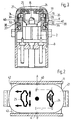
- Fig. 3 shows the cap 21 with molded symbol windows 25,26 and part of the reflector 19, in which the Luminous body 15 protrudes.
- the actuator 16 has the height of the vertical in Fig. 1 longitudinal axis penetrating point G to the viewer plane K two aligned bearing openings 29.30, in the corresponding stub shaft 32.33 of the housing are engaged. To facilitate snapping into place carry the stub axles 34.35, the corresponding Assigned slopes of the actuator 16 are.
Landscapes
- Switches With Compound Operations (AREA)
- Switches Operated By Changes In Physical Conditions (AREA)
- Tumbler Switches (AREA)
Description
- Fig. 1
- einen Längsschnitt durch eine erfindungsgemäße Schalteranordnung,
- Fig. 2
- eine Draufsicht auf die Schalteranordnung nach Fig. 1 etwas verkleinert dargestellt und
- Fig. 3
- einen Schnitt etwa längs der Linie A,B,C,D,E,F in Fig. 2.
Claims (14)
- Elektrische Schalteranordnung, bestehend aus mindestens einem in dem Gehäuse (8) befindlichen Schalter (1,2), einem auf den Schalter (1,2) unmittelbar einwirkenden Betätiger (16) und einer gegenüber dem Gehäuse schwenkbar gelagerten Betätigungskappe (21), welche an dem Betätiger (16) angreift, wobei die Kappe gegenüber dem Betätiger quer zur Schwenkebene der Kappe verschiebbar ist, dadurch gekennzeichnet, daß der Betätiger (16) unmittelbar an dem Gehäuse(8) drehbar gelagert ist, daß die Betätigungskappe(21) mit ihrem Boden (20) auf dem Betätiger (16) aufliegt und daß an den parallel zur Schwenkebene verlaufenden Seitenflächen der Betätigungskappe (21) sich nach außen verjüngende, Vorsprünge zur Anlage an der Innenwand einer Blendenöffnung abstehen.
- Schalteranordnung nach Anspruch 1, dadurch gekennzeichnet, daß die Betätigungskappe im Bereich der Lagerung des Betätigers (16) im Gehäuse (8) gegen den Betätiger (16) in Richtung der Lagerachse (K) des Betätigers (16) verschiebbar geführt ist.
- Schalteranordnung nach einem der vorangegangenen Ansprüche, dadurch gekennzeichnet, daß der Betätiger (16) mit zwei kreisabschnittförmigen Ansätzen (36,37) in entsprechend bogenförmige Ausschnitte (38,39) der Betätigungskappe (21) eingreift.
- Schalteranordnung nach Anspruch 3, dadurch gekennzeichnet, daß die Zentren der kreisabschnittförmigen Ansätze (36,37) auf der Lagerachse (K) des Betätigers (16) liegen.
- Schalteranordnung nach einem der vorangegangenen Ansprüche, dadurch gekennzeichnet, daß die Vorsprünge eine Spitze aufweisen oder halbkugelförmig ausgestattet sind.
- Schalteranordnung nach Anspruch 5, dadurch gekennzeichnet, daß die Betätigungskappe (21) zwei symmetrisch angeordnete Vorsprünge (40,41) besitzt, die auf der Lagerachse (K) des Betätigers (16) liegen.
- Schalteranordnung nach einem der vorangegangenen Ansprüche, dadurch gekennzeichnet, daß der Betätiger (16) als Lagerstellen zwei miteinander fluchtende Lageröffnungen (30,31) besitzt, in welche zwei zugeordnete vorspringende Achsstummel (32,33) des Gehäuses (8) aufgerastet sind.
- Schalteranordnung nach Anspruch 7, dadurch gekennzeichnet, daß die Innenflächen der Ansätze (36,37) in die Lagerflächen der Lageröffnungen (30,31) übergehen und die gleiche Kontur besitzen.
- Schalteranordnung nach Anspruch 7 oder 8, dadurch gekennzeichnet, daß die Ansätze (36,37) des Betätigers (16) und die Achsstummel (32,33) des Gehäuses (8) in Zusammenbaurichtung mit dem Betätiger abgeschrägt sind.
- Schalteranordnung nach einem der vorangegangenen Ansprüche, dadurch gekennzeichnet, daß die die Lageröffnungen (30,31) tragenden Flächen des Betätigers (16) über Stege (44,45) an den Betätiger (16) angeformt sind.
- Schalteranordnung nach einem der vorangegangenen Ansprüche, dadurch gekennzeichnet, daß an den Betätiger (16) Reflektoren (18,19) für an dem Schalter angeordnete Leuchtkörper (14,15) angeformt sind und die Stirnflächen der Reflektoren die Auflageflächen der Betätigungskappe (21) auf den Betätiger (16) bilden.
- Schalteranordnung nach Anspruch 11, dadurch gekennzeichnet, daß die Betätigungskappe (21) aus reflektierendem und/oder durchscheinendem Material, vorzugsweise weißem Kunststoff, geformt ist.
- Schalteranordnung nach einem der Ansprüche 11 oder 12, dadurch gekennzeichnet, daß die Betätigungskappe (21) aus zwei Kunststoffschichten besteht, und zwar einer schwarzen äußeren und einer weißen durchscheinenden inneren Schicht.
- Schalteranordnung nach einem der vorangegangenen Ansprüche, dadurch gekennzeichnet, daß der Betätiger (16) im wesentlichen symmetrisch ausgestaltet ist und zum Höhenausgleich des Abstandes des Kappenbodens von der Abstützfläche des Betätigers die Kappe mit Querstegen (22,23) versehen ist.
Applications Claiming Priority (3)
| Application Number | Priority Date | Filing Date | Title |
|---|---|---|---|
| DE4410697 | 1994-03-28 | ||
| DE4410697A DE4410697A1 (de) | 1994-03-28 | 1994-03-28 | Schalteranordnung für Einbauschalter mit schwimmend gelagerter Betätigungskappe |
| PCT/EP1995/001063 WO1995026564A1 (de) | 1994-03-28 | 1995-03-22 | Schalteranordnung für einbauschalter mit schwimmend gelagerter betätigungskappe |
Publications (2)
| Publication Number | Publication Date |
|---|---|
| EP0753198A1 EP0753198A1 (de) | 1997-01-15 |
| EP0753198B1 true EP0753198B1 (de) | 1999-07-14 |
Family
ID=6514039
Family Applications (1)
| Application Number | Title | Priority Date | Filing Date |
|---|---|---|---|
| EP95914286A Expired - Lifetime EP0753198B1 (de) | 1994-03-28 | 1995-03-22 | Schalteranordnung für einbauschalter mit schwimmend gelagerter betätigungskappe |
Country Status (6)
| Country | Link |
|---|---|
| US (1) | US5850062A (de) |
| EP (1) | EP0753198B1 (de) |
| JP (1) | JPH09510823A (de) |
| DE (2) | DE4410697A1 (de) |
| ES (1) | ES2133758T3 (de) |
| WO (1) | WO1995026564A1 (de) |
Families Citing this family (14)
| Publication number | Priority date | Publication date | Assignee | Title |
|---|---|---|---|---|
| DE19718979B4 (de) * | 1997-05-05 | 2007-11-08 | Delphi Technologies, Inc., Troy | Multifunktionstastschalter |
| US6013885A (en) * | 1999-01-21 | 2000-01-11 | Carlingswitch, Inc. | Rocker switch with lamp module |
| JP3765683B2 (ja) * | 1999-03-11 | 2006-04-12 | アルプス電気株式会社 | 照光式スイッチ装置 |
| US6160231A (en) * | 1999-12-03 | 2000-12-12 | Methode Electronics, Inc. | Button retention feature |
| DE20110507U1 (de) * | 2001-06-27 | 2002-09-05 | Grote & Hartmann GmbH & Co KG, 42369 Wuppertal | Kontaktiervorrichtung |
| KR100593167B1 (ko) * | 2004-07-20 | 2006-06-26 | 주식회사 현대오토넷 | 조명 빛 간섭 차단 버튼을 갖춘 히터콘트롤 |
| US6933453B1 (en) * | 2004-10-20 | 2005-08-23 | Shin Chin Industrial Co., Ltd. | Switch capable of showing a circle of light thereon |
| JP4426952B2 (ja) * | 2004-11-15 | 2010-03-03 | アルプス電気株式会社 | 照光式スライドスイッチ装置 |
| US7629548B2 (en) * | 2005-07-14 | 2009-12-08 | Access Business Group International Llc | Control panel assembly |
| WO2007101674A1 (de) * | 2006-03-08 | 2007-09-13 | Rsl Rodust & Sohn Lichttechnik Gmbh | Einbauvorrichtung |
| DE102007017710A1 (de) | 2007-04-14 | 2008-10-16 | Eao Automotive Gmbh & Co. Kg | Schaltelement |
| JP4642836B2 (ja) * | 2007-12-27 | 2011-03-02 | 株式会社沖データ | 画像形成装置 |
| DE102008048708A1 (de) | 2008-09-24 | 2010-03-25 | Eao Automotive Gmbh & Co. Kg | Modulartiges Element |
| US20180283100A1 (en) * | 2015-06-15 | 2018-10-04 | David R. Hall | Retractable privacy system and method |
Family Cites Families (11)
| Publication number | Priority date | Publication date | Assignee | Title |
|---|---|---|---|---|
| FR1558448A (de) * | 1967-12-15 | 1969-02-28 | ||
| SU1350686A1 (ru) * | 1985-07-02 | 1987-11-07 | Предприятие П/Я В-8670 | Кнопочный переключатель |
| DE3533055A1 (de) * | 1985-09-17 | 1987-03-26 | Swf Auto Electric Gmbh | Schalter, insbesondere fuer kraftfahrzeuge |
| SU1554042A1 (ru) * | 1987-07-16 | 1990-03-30 | В.В. Ивановский, | Комбинированный светосигнальный индикатор |
| DE8816238U1 (de) * | 1988-12-31 | 1989-03-02 | Priesemuth, Wolfgang, 25524 Breitenburg | Tastschalter |
| DE3932872A1 (de) * | 1989-10-02 | 1991-04-11 | Rittershaus & Blecher Gmbh | Verfahren und vorrichtung zum einmischen einer flockungsmittelloesung in eine zu filtrierende truebe |
| DE3938872A1 (de) * | 1989-11-24 | 1991-05-29 | Bentz & Sohn Melitta | Geraeteschalter fuer elektrogeraete |
| US5187336A (en) * | 1990-05-30 | 1993-02-16 | The Cherry Corporation | Switch assembly with transfer actuator |
| DE4107182A1 (de) * | 1991-03-06 | 1992-09-10 | Daimler Benz Ag | Lichtdurchlaessiges, undurchsichtiges und mittels einer lichtquelle hinterleuchtbares farbiges schalterelement |
| DE4115741A1 (de) * | 1991-05-14 | 1992-11-19 | Hartmut S Engel | Schalter |
| DE4214794B4 (de) * | 1992-05-04 | 2005-03-24 | Marquardt Gmbh | Elektrische Schalteranordnung |
-
1994
- 1994-03-28 DE DE4410697A patent/DE4410697A1/de not_active Withdrawn
-
1995
- 1995-03-22 DE DE59506388T patent/DE59506388D1/de not_active Expired - Fee Related
- 1995-03-22 WO PCT/EP1995/001063 patent/WO1995026564A1/de not_active Ceased
- 1995-03-22 JP JP7524946A patent/JPH09510823A/ja active Pending
- 1995-03-22 ES ES95914286T patent/ES2133758T3/es not_active Expired - Lifetime
- 1995-03-22 EP EP95914286A patent/EP0753198B1/de not_active Expired - Lifetime
- 1995-03-22 US US08/718,407 patent/US5850062A/en not_active Expired - Fee Related
Also Published As
| Publication number | Publication date |
|---|---|
| DE4410697A1 (de) | 1995-10-05 |
| DE59506388D1 (de) | 1999-08-19 |
| EP0753198A1 (de) | 1997-01-15 |
| WO1995026564A1 (de) | 1995-10-05 |
| ES2133758T3 (es) | 1999-09-16 |
| US5850062A (en) | 1998-12-15 |
| JPH09510823A (ja) | 1997-10-28 |
Similar Documents
| Publication | Publication Date | Title |
|---|---|---|
| EP0753198B1 (de) | Schalteranordnung für einbauschalter mit schwimmend gelagerter betätigungskappe | |
| DE3844484A1 (de) | Tastschalter | |
| DE10027446A1 (de) | Elektrischer Schalter | |
| EP0759206B1 (de) | Abgedichteter kippschalter mit leuchtanzeige | |
| EP0372160A1 (de) | Beleuchtete Reguliervorrichtung zur Betätigung einer Belüftungseinrichtung oder dgl. in einem Kraftfahrzeug | |
| EP0413776A1 (de) | Lenkstockschalter für kraftfahrzeuge. | |
| DE4222335C2 (de) | Drehschalter | |
| DE3133134A1 (de) | Elektrischer schalter, insbesondere fuer kraftfahrzeuge | |
| DE3129210C2 (de) | Elektrische Schaltvorrichtung | |
| EP2302655B1 (de) | Elektrischer Schalter | |
| DE29716198U1 (de) | Elektrisches Installationsgerät, insbesondere Taster, Seller oder Schalter | |
| DE19514539C2 (de) | Mehrfunktionsschalter, insbesondere Spiegelverstellschalter für ein Kraftfahrzeug | |
| DE4243319A1 (en) | Rotary indexing electrical switch - has rotary contacts arranged around housing and operated by indexing cam that displaces plungers. | |
| DE19544467C1 (de) | Elektrische Signalgabeeinrichtung | |
| EP0726587B1 (de) | Drehschalter mit zwei jeweils eine Kontaktanordnung aufweisenden Gehäuseteilen | |
| DE19544807C2 (de) | Leuchte | |
| EP0633586B1 (de) | Elektrisches Schaltgerät | |
| DE4214794B4 (de) | Elektrische Schalteranordnung | |
| DE2148921A1 (de) | Elektrischer Schalter | |
| EP0673049B1 (de) | Elektrischer Tastschalter | |
| DE2625780C3 (de) | Elektrischer Schalter mit Beleuchtungseinrichtung | |
| DE29519317U1 (de) | Beleuchtungsvorrichtung | |
| DE19727514C1 (de) | Elektrische Schalteranordnung | |
| DE4015598C2 (de) | ||
| EP0777246A2 (de) | Elektrischer Schalter |
Legal Events
| Date | Code | Title | Description |
|---|---|---|---|
| PUAI | Public reference made under article 153(3) epc to a published international application that has entered the european phase |
Free format text: ORIGINAL CODE: 0009012 |
|
| 17P | Request for examination filed |
Effective date: 19961028 |
|
| AK | Designated contracting states |
Kind code of ref document: A1 Designated state(s): DE ES FR GB IT |
|
| 17Q | First examination report despatched |
Effective date: 19971119 |
|
| GRAG | Despatch of communication of intention to grant |
Free format text: ORIGINAL CODE: EPIDOS AGRA |
|
| ITF | It: translation for a ep patent filed | ||
| GRAG | Despatch of communication of intention to grant |
Free format text: ORIGINAL CODE: EPIDOS AGRA |
|
| GRAH | Despatch of communication of intention to grant a patent |
Free format text: ORIGINAL CODE: EPIDOS IGRA |
|
| GRAH | Despatch of communication of intention to grant a patent |
Free format text: ORIGINAL CODE: EPIDOS IGRA |
|
| GRAA | (expected) grant |
Free format text: ORIGINAL CODE: 0009210 |
|
| AK | Designated contracting states |
Kind code of ref document: B1 Designated state(s): DE ES FR GB IT |
|
| GBT | Gb: translation of ep patent filed (gb section 77(6)(a)/1977) |
Effective date: 19990714 |
|
| REF | Corresponds to: |
Ref document number: 59506388 Country of ref document: DE Date of ref document: 19990819 |
|
| ET | Fr: translation filed | ||
| REG | Reference to a national code |
Ref country code: ES Ref legal event code: FG2A Ref document number: 2133758 Country of ref document: ES Kind code of ref document: T3 |
|
| PLBE | No opposition filed within time limit |
Free format text: ORIGINAL CODE: 0009261 |
|
| STAA | Information on the status of an ep patent application or granted ep patent |
Free format text: STATUS: NO OPPOSITION FILED WITHIN TIME LIMIT |
|
| 26N | No opposition filed | ||
| REG | Reference to a national code |
Ref country code: GB Ref legal event code: IF02 |
|
| PGFP | Annual fee paid to national office [announced via postgrant information from national office to epo] |
Ref country code: FR Payment date: 20020318 Year of fee payment: 8 |
|
| PGFP | Annual fee paid to national office [announced via postgrant information from national office to epo] |
Ref country code: ES Payment date: 20030325 Year of fee payment: 9 |
|
| REG | Reference to a national code |
Ref country code: GB Ref legal event code: 732E |
|
| PG25 | Lapsed in a contracting state [announced via postgrant information from national office to epo] |
Ref country code: ES Free format text: LAPSE BECAUSE OF NON-PAYMENT OF DUE FEES Effective date: 20040323 |
|
| PGFP | Annual fee paid to national office [announced via postgrant information from national office to epo] |
Ref country code: GB Payment date: 20040414 Year of fee payment: 10 |
|
| PG25 | Lapsed in a contracting state [announced via postgrant information from national office to epo] |
Ref country code: FR Free format text: LAPSE BECAUSE OF NON-PAYMENT OF DUE FEES Effective date: 20041130 |
|
| REG | Reference to a national code |
Ref country code: FR Ref legal event code: ST |
|
| PG25 | Lapsed in a contracting state [announced via postgrant information from national office to epo] |
Ref country code: IT Free format text: LAPSE BECAUSE OF NON-PAYMENT OF DUE FEES;WARNING: LAPSES OF ITALIAN PATENTS WITH EFFECTIVE DATE BEFORE 2007 MAY HAVE OCCURRED AT ANY TIME BEFORE 2007. THE CORRECT EFFECTIVE DATE MAY BE DIFFERENT FROM THE ONE RECORDED. Effective date: 20050322 Ref country code: GB Free format text: LAPSE BECAUSE OF NON-PAYMENT OF DUE FEES Effective date: 20050322 |
|
| REG | Reference to a national code |
Ref country code: ES Ref legal event code: FD2A Effective date: 20040323 |
|
| GBPC | Gb: european patent ceased through non-payment of renewal fee |
Effective date: 20050322 |
|
| PGFP | Annual fee paid to national office [announced via postgrant information from national office to epo] |
Ref country code: DE Payment date: 20080311 Year of fee payment: 14 |
|
| PG25 | Lapsed in a contracting state [announced via postgrant information from national office to epo] |
Ref country code: FR Free format text: LAPSE BECAUSE OF NON-PAYMENT OF DUE FEES Effective date: 20030331 |
|
| PG25 | Lapsed in a contracting state [announced via postgrant information from national office to epo] |
Ref country code: DE Free format text: LAPSE BECAUSE OF NON-PAYMENT OF DUE FEES Effective date: 20091001 |