EP0753198B1 - Switch assembly for a built-in switch with a float-mounted actuator cover - Google Patents
Switch assembly for a built-in switch with a float-mounted actuator cover Download PDFInfo
- Publication number
- EP0753198B1 EP0753198B1 EP95914286A EP95914286A EP0753198B1 EP 0753198 B1 EP0753198 B1 EP 0753198B1 EP 95914286 A EP95914286 A EP 95914286A EP 95914286 A EP95914286 A EP 95914286A EP 0753198 B1 EP0753198 B1 EP 0753198B1
- Authority
- EP
- European Patent Office
- Prior art keywords
- actuator
- cap
- switch configuration
- electric switch
- housing
- Prior art date
- Legal status (The legal status is an assumption and is not a legal conclusion. Google has not performed a legal analysis and makes no representation as to the accuracy of the status listed.)
- Expired - Lifetime
Links
Images

Classifications
-
- H—ELECTRICITY
- H01—ELECTRIC ELEMENTS
- H01H—ELECTRIC SWITCHES; RELAYS; SELECTORS; EMERGENCY PROTECTIVE DEVICES
- H01H23/00—Tumbler or rocker switches, i.e. switches characterised by being operated by rocking an operating member in the form of a rocker button
- H01H23/02—Details
- H01H23/025—Light-emitting indicators
-
- H—ELECTRICITY
- H01—ELECTRIC ELEMENTS
- H01H—ELECTRIC SWITCHES; RELAYS; SELECTORS; EMERGENCY PROTECTIVE DEVICES
- H01H23/00—Tumbler or rocker switches, i.e. switches characterised by being operated by rocking an operating member in the form of a rocker button
- H01H23/02—Details
- H01H23/12—Movable parts; Contacts mounted thereon
- H01H23/14—Tumblers
- H01H23/143—Tumblers having a generally flat elongated shape
Definitions
- the invention relates to an electrical switch arrangement for installation in a receptacle, the switch up on a cutout for the actuating cap by a Aperture of the recording can be covered.
- the size of the aperture for the Key cap can be chosen accordingly wide. Besides, is disturbing that especially with illuminated switches, the actuating cap is offset within the aperture lies what the of these equipped with the switches Recording gives a bad look.
- the invention is therefore based on a switch arrangement deriving from the preamble of claim 1 Genus.
- the object of the invention is to the actuator to arrange the cap captively and at the same time the bearing points between cap, actuator and Arrange housing in close proximity to each other to avoid undesired tilting moments within the switch.
- the task is characterized by the Resulting combination of features solved.
- the invention therefore consists in the No longer to pinch the actuator between the cap and the housing, but to store directly on the housing.
- the advantage is that just that component in Housing is stored, through which the switch Switching forces to be transmitted immediately become. Regardless of this, is also known per se Way for a storage of the actuating cap opposite the housing.
- the combination of features is recommended according to claim 11 according to which the actuator at the same time as a reflector for the to be operated Switching bulbs is used. Recommends it, the actuator preferably made of light plastic to manufacture, in particular by an injection molding process.
- the 1 has two switches 1,2 and possibly a third switch 3, which on a Base plate 4 are mounted and electrically connected.
- the base plate 4 sits on a connection plate 5, which carries a plug 6 with contacts 7, the are anchored in the connection plate 5 and by the Base plate 4 protrude and there with electrical lines are connected. These lines then lead in a more suitable manner Way to the individual contacts of the switches 1,2 or 3rd
- a housing 8 is placed on the connection plate 5 and releasably connected to it. Is also solvable via a screw connection, the base plate 4 with the Connection plate 5 connected. You get one with switches Provided housing 8, which via locking lugs 9 in a recording not shown in Fig. 1 snapped can be. Approximately at the top edge 10 of the housing 8 an aperture 11 (FIG. 2) is held by the receptacle, which has an aperture, that in Fig. 2 from above seen, covering parts of the switch.
- the switch arrangement is still with an actuator 16 provided, on the one hand pivotable in the point G is stored relative to the housing and continues to do so serves to be able to act on the actuating sleeves 12, 13 what with the help of the bottom surfaces of the to the actuator 16 belonging reflectors 18, 19 happens.
- the reflectors 18,19 have openings through which the filament 14.15 protrude and for lighting the floor area 20 provide an actuating cap 21.
- the actuation cap 21 acts on crossbars 22, 23 on the actuator 16 a by this in Fig. 1 perpendicular to Cross webs extending on the observer plane on the end face attack the reflectors 18, 19. Additionally supports the middle area 24 of the actuating cap 16 a lattice-shaped section of the actuator 16 from.
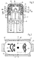
- Fig. 3 shows the cap 21 with molded symbol windows 25,26 and part of the reflector 19, in which the Luminous body 15 protrudes.
- the actuator 16 has the height of the vertical in Fig. 1 longitudinal axis penetrating point G to the viewer plane K two aligned bearing openings 29.30, in the corresponding stub shaft 32.33 of the housing are engaged. To facilitate snapping into place carry the stub axles 34.35, the corresponding Assigned slopes of the actuator 16 are.
Description
Die Erfindung betrifft eine elektrische Schalteranordnung zum Einbau in eine Aufnahme, wobei der Schalter bis auf einen Ausschnitt für die Betätigungskappe durch eine Blende der Aufnahme abdeckbar ist.The invention relates to an electrical switch arrangement for installation in a receptacle, the switch up on a cutout for the actuating cap by a Aperture of the recording can be covered.
Für den Einbau der Schalter in die Aufnahme, insbesondere, wenn mehrere Schalter eingebaut werden sollen, müssen Toleranzen vorgesehen sein. Dabei kann die Lage der zu der Aufnahme gehörenden Blende sich gegenüber dieser um einen bestimmten Betrag verschieben. Als Folge davon müßte auch die durch die Blende eingerahmte Betätigungskappe entsprechend verschoben werden. Dies ist bei üblichen Schaltern aber nicht möglich, weil die Betätigungskappe wieder fest mit dem Schaltergehäuse verbunden ist, so daß die Lage der Betätigungskappe durch die Lage der Schalter festgelegt ist.For the installation of the switches in the receptacle, in particular, if several switches are to be installed, Tolerances should be provided. The location of the aperture belonging to the recording is opposite this move by a certain amount. As a consequence of this would also need the actuating cap framed by the panel be moved accordingly. This is common Switches are not possible because of the actuation cap is firmly connected to the switch housing again, so that the location of the actuating cap by the location of the Switch is set.
Als Folge davon muß die Größe der Blendenöffnung für die Tastkappe entsprechend weit gewählt werden. Außerdem ist störend, daß insbesondere bei beleuchteten Schaltern, die Betätigungskappe innerhalb der Blendenöffnung versetzt liegt, was der dieser mit den Schaltern bestückten Aufnahme ein fehlerhaftes Aussehen verleiht. As a result, the size of the aperture for the Key cap can be chosen accordingly wide. Besides, is disturbing that especially with illuminated switches, the actuating cap is offset within the aperture lies what the of these equipped with the switches Recording gives a bad look.
Aus der DE-OS 42 14 794 ist es bekannt, die Betätigungskappe aus den o.g. Gründen gegenüber dem Schaltergehäuse schwimmend zu lagern. Das bedeutet, daß sich die Lage der Betätigungskappe unabhängig von der Lage des Schalters in gewissen Grenzen an die Lage der Blendenöffnung anzupassen vermag. Bei der bekannten Schalteranordnung ist die Betätigungskappe in Zapfen an dem Schaltergehäuse schwimmend gelagert. Die Kappe selbst stützt sich mit ihrem Boden an einem Betätigungsorgan ab, so daß die Kappe mittelbar über das Betätigungsorgan auf den Schalter einwirken kann. Nachteilig bei der bekannten Schalteranordnung ist es, daß die Lagerbereiche zwischen Betätigungskappe und Betätigungseinrichtung einerseits und Betätigungskappe und Gehäuse andererseits vergleichsweise weit auseinanderliegen, so daß bei tolerierter Fertigung unerwünschte Kippmomente und Materialspanungen entstehen können. Weiterhin ist die Betätigungseinrichtung gegenüber der Betätigungskappe in Nuten geführt, so daß die Betätigungseinrichtung gegenüber der Kappe nicht unverlierbar gehalten ist.From DE-OS 42 14 794 it is known the actuating cap from the above Reasons compared to the switch housing to store floating. That means the situation the actuating cap regardless of the position of the switch within certain limits to the position of the aperture is able to adapt. In the known switch arrangement is the actuating cap in the pin on the switch housing floating. The cap itself supports itself their bottom on an actuator, so that the Cap indirectly via the actuator on the switch can act. A disadvantage of the known switch arrangement it is that the bearing areas between the actuating cap and actuator on the one hand and Operating cap and housing, on the other hand, comparatively are far apart so that when tolerated Production of undesired tilting moments and material tensions can arise. Furthermore, the actuator guided in grooves relative to the actuating cap, see above that the actuator against the cap is not is held captive.
Ein weiterer Nachteil der bekannten Schaltungsanordnung wird darin gesehen, daß die Kappe vergleichsweise große Lageraugen zur Aufnahme der Gehäusezapfen besitzt, wobei die Randfläche der Lageraugen gleichzeitig zur seitlichen Abstützung der Kappe an der Blendenöffnung der die Kappe umgebenden Blende dient. Aufgrund der relativ großen Anlageflächen der Nutenführung sowie der großen Anlagefläche der Augen an der Blende, ist die Bewegung der Kappe mit einer vergleichsweise großen Reibung behaftet.Another disadvantage of the known circuit arrangement is seen in the fact that the cap is comparatively large Has bearing eyes for receiving the housing pin, wherein the edge surface of the bearing eyes simultaneously to the side Support the cap on the aperture of the Cap surrounding bezel is used. Because of the relatively large Contact surfaces of the groove guide and the large contact surface of the eyes on the bezel, is the movement of the Cap with a comparatively large friction.
Die Erfindung geht daher aus von einer Schalteranordnung der sich aus dem Oberbegriff des Anspruchs 1 ergebenden Gattung. Aufgabe der Erfindung ist es, den Betätiger gegenüber der Kappe unverlierbar anzuordnen und gleichzeitig die Lagerstellen zwischen Kappe, Betätiger und Gehäuse in unmittelbarer Nähe zueinander anzuordnen, um unerwünschte Kippmomente innerhalb des Schalters zu vermeiden.The invention is therefore based on a switch arrangement deriving from the preamble of claim 1 Genus. The object of the invention is to the actuator to arrange the cap captively and at the same time the bearing points between cap, actuator and Arrange housing in close proximity to each other to avoid undesired tilting moments within the switch.
Die Aufgabe wird durch die sich aus Anspruch 1 ergebende Merkmalskombination gelöst. Die Erfindung besteht im Prinzip also darin, den Betätiger nicht mehr zwischen Kappe und Gehäuse einzuklemmen, sondern unmittelbar am Gehäuse zu lagern. Der Vorteil besteht darin, daß gerade dasjenige Bauteil im Gehäuse gelagert wird, über welches die auf den Schalter unmittelbar zu übertragenden Schaltkräfte aufgebracht werden. Unabhängig davon ist auch in an sich bekannter Weise für eine Lagerung der Betätigungskappe gegenüber dem Gehäuse gesorgt.The task is characterized by the Resulting combination of features solved. In principle, the invention therefore consists in the No longer to pinch the actuator between the cap and the housing, but to store directly on the housing. Of the The advantage is that just that component in Housing is stored, through which the switch Switching forces to be transmitted immediately become. Regardless of this, is also known per se Way for a storage of the actuating cap opposite the housing.
Um zwischen Kappe, Betätiger und dem zu bedienenden
Schalter möglichst kurze Kraftwege zu haben, empfiehlt
sich in Weiterbildung der Erfindung die Merkmalskombination
nach Anspruch 2. Danach wird der Hebel für die über
beide Lager übertragende Kraft besonders kurz und die
erzeugten Kippmomente vergleichsweise vernachlässigbar.In order between cap, actuator and the one to be operated
It is recommended that switches have the shortest possible force paths
the combination of features in a development of the invention
according to
Um den Betätiger besonders einfach montieren zu können
und um über die Lagerung zwischen Betätigungskappe und
Betätiger ein zusätzliches Drehmoment übertragen zu können,
empfiehlt sich in Weiterbildung der Erfindung die
Merkmalskombination nach Anspruch 3. An sich wäre es
auch denkbar, daß die Kappe mit dem Betätiger über eine
kreisrunde Lagerstelle verbunden ist. Drehmomente im
Lagerbereich können auf diese Weise aber von der Kappe
nicht auf den Betätiger übertragen werden. Zum anderen
schafft die hier angegebene Konstruktion Raum für die im
Zusammenhang mit Anspruch 5 erläuterten Merkmale. Weiterhin
wird durch eine derartige Konstruktion die Verrastung
zwischen Betätigungskappe und Betätiger erreicht,
da die teilkreisförmigen Ansätze vorzugsweise so gelegt
werden, daß sie in Zusammenbaurichtung der beiden Bauelemente
möglichst wenig Dehnung für die überrastenden
Seitenwände der Betätigungskappe erfordern.In order to be able to mount the actuator particularly easily
and about the storage between the actuating cap and
Actuator to be able to transmit an additional torque,
is recommended in further development of the invention
Combination of features according to
Um die zentrierende Wirkung beim Zusammenbau zwischen Betätigungskappe und Betätiger zu erhöhen, empfiehlt sich in Weiterbildung der Erfindung die Merkmalskombination nach Anspruch 4. Da die Ausschnitte nur teilkreisförmig sind und somit beispielsweise die Form eines Halbrings besitzen, bleibt an den Seitenwänden in Verlängerung der Lagerachse der Betätigungskappe Material etwa in der Form eines kleinen Halbkreises stehen. Dies läßt sich vorteilhaft für die Anwendung der in Anspruch 5 aufgeführten Merkmale ausnutzen. Auf diese Weise läßt sich die durch die Anlage der Seitenwände der Kappe an der Innenwand der Blendenöffnung sich ergebende Reibung minimieren. Zum einen liegt nämlich die Spitze des Vorsprungs in der Verlängerung der Drehachse der Betätigungskappe, so daß der Vorsprung gegenüber der Blendenfläche nur eine Drehbewegung, aber keine Schwenkbewegung ausführt. Zum anderen ist die Anlagefläche der Vorsprünge an der Blendenfläche punktförmig, so daß auch hierdurch die Reibung vernachlässigbar klein wird (Merkmale nach Anspruch 6).To the centering effect when assembling between It is recommended to increase the actuating cap and actuator the combination of features in a development of the invention according to claim 4. Since the cutouts only part-circular are and thus, for example, the shape of a Own half rings, remains on the side walls in extension the bearing axis of the actuating cap material stand in the shape of a small semicircle. This can be advantageous for the application of the claim Take advantage of the 5 listed features. That way by the installation of the side walls of the cap resulting friction on the inner wall of the aperture minimize. On the one hand, the tip of the lead lies in the extension of the axis of rotation of the actuating cap, so that the protrusion against the aperture surface only a rotating movement, but no swiveling movement executes. On the other hand, the contact surface is the projections punctiform on the diaphragm surface, so that this too the friction becomes negligibly small (characteristics according to claim 6).
Um den Zusammenbau zwischen Betätiger und Schaltergehäuse zu vereinfachen, empfiehlt sich die Merkmalskombination nach Anspruch 7. Dabei geht man zweckmäßigerweise so vor, daß die Lageröffnungen des Betätigers die Achsstummel von außen umgreifen, so daß der Betätiger auf die Lagerstummel aufgerastet werden kann und so in einfacher Weise drehbar gelagert ist. Selbstverständlich ist es auch möglich, daß Achsstummel an dem Betätiger angeordnet werden, die in entsprechende Öffnungen des Gehäuses einrasten. Man erhält dann allerdings relativ kleine Führungsflächen für das zu spreizende Teil, was zu Beschädigungen der Lagerstelle führen kann.The assembly between the actuator and the switch housing To simplify the combination of features is recommended according to claim 7. It is convenient so that the bearing openings of the actuator stub the axle reach around from the outside, so that the actuator the bearing stub can be snapped on and thus in easier Way is rotatably mounted. Of course it is also possible that stub axles on the actuator are arranged in corresponding openings of the Snap the housing into place. However, you then get relative small guide surfaces for the part to be spread, what can damage the bearing.
Eine besonders einfache Form ergibt sich, wenn entsprechend
Anspruch 8 die Ansätze Teile eines verlängernden
Lagerauges für den Betätiger sind. Damit können die
Lagerstummel des Gehäuses ggf. an Teilen der Innenfläche
der Ansätze zur Anlage kommen und so die Lagerfläche
vergrößern. Auch hierdurch wird ein zusätzlicher
Toleranzausgleich erreicht.A particularly simple form is obtained if
Um das rastende Zusammenfügen der o.g. Einzelteile des Schalters zu erleichtern, empfiehlt sich die Anwendung der Merkmalskombination nach Anspruch 9. Danach sind im Prinzip die zu verrastenden Bauelemente mit Auflaufschrägen versehen, die zu der gewünschten Spreizwirkung führen. Nach Erreichen der aufgespreizten Lage werden die miteinander zu verbindenden Teile über entsprechende Hinterschneidungen miteinander verrastet. Die Auflaufschrägen sind dabei so gelegt, daß in Zusammenbaurichtung die miteinander zu verrastenden Flächen aus ihrer Ursprungslage so weit herausgebogen werden, bis sie nach Erreichen ihrer Endlage unter Aufnahme des entsprechenden Lagerkörpers zurückfedern können. To snap together the above Individual parts of the The application is recommended to facilitate the switch the combination of features according to claim 9 Principle of the components to be locked with bevels provided that to the desired spreading effect to lead. After reaching the spread position the parts to be connected to one another via corresponding Undercuts locked together. The ramp are placed so that in the direction of assembly the surfaces to be locked together from their Original position are bent out so far, until after Reaching their end position, including the corresponding one Can spring back bearing body.
Um das Aufbringen des Betätigers auf das Gehäuse zu vereinfachen,
empfiehlt sich die Verwendung der
Merkmalskombination nach Anspruch 10. Danach wird die
für den Zusammenbau zwischen Betätiger und Gehäuse benötigte
Kraft dadurch verringert, daß die Seitenflächen
des Betätigers über Stegen mit einer vergrößerten Elastizität
versehen werden, so daß ein Zerbrechen des Betätigers
beim Aufrasten auf das Gehäuse weitgehend ausgeschlossen
ist.To make it easier to attach the actuator to the housing,
it is recommended to use the
Combination of features according to
In Weiterbildung der Erfindung empfiehlt sich die Merkmalskombination
nach Anspruch 11 gemäß der der Betätiger
gleichzeitig als Reflektor für aus den zu betätigenden
Schaltern ragende Lampen verwendet wird. Dabei empfiehlt
es sich, den Betätiger bevorzugt aus hellem Kunststoff
zu fertigen, insbesondere durch ein Spritzgußverfahren.In a further development of the invention, the combination of features is recommended
according to
Um die Helligkeit in dem zwischen Betätiger und Kappe
liegenden Raum zu erhöhen, und um ggf. die Kappe mit
eingespritzten Symbolen zu versehen, empfiehlt sich in
Weiterbildung der Erfindung die Merkmalskombination nach
Anspruch 13.To the brightness in the between actuator and cap
to increase lying space, and if necessary with the cap
Providing injected symbols is recommended in
Development of the invention according to the combination of
Um unabhängig von der Formgestaltung der Kappe den gleichen
Betätiger einsetzen zu können und um den Betätiger
in mehreren Einbaulagen einbauen zu können, empfiehlt
sich in Weiterbildung der Erfindung die Merkmalskombination
nach Anspruch 14. Danach wird durch Stege in dem
Boden der Betätigungskappe der andererseits entstehende
Abstand zwischen Boden und Stirnfläche des Betätigers
überbrückt. Und gleichzeitig die Materialstärke der Kappe
ansonsten unbeeinflußt gelassen. To the same regardless of the shape of the cap
To be able to use the actuator and around the actuator
To be able to install in several installation positions is recommended
the combination of features in a development of the invention
according to
Ein Ausführungsbeispiel der Erfindung wird nachfolgend anhand der Zeichnung erläutert. Darin zeigt
- Fig. 1
- einen Längsschnitt durch eine erfindungsgemäße Schalteranordnung,
- Fig. 2
- eine Draufsicht auf die Schalteranordnung nach Fig. 1 etwas verkleinert dargestellt und
- Fig. 3
- einen Schnitt etwa längs der Linie A,B,C,D,E,F in Fig. 2.
- Fig. 1
- 2 shows a longitudinal section through a switch arrangement according to the invention,
- Fig. 2
- a top view of the switch assembly of FIG. 1 shown somewhat reduced and
- Fig. 3
- a section approximately along the line A, B, C, D, E, F in Fig. 2nd
Die Schaltungsanordnung gemäß Fig. 1 besitzt zwei Schalter
1,2 und ggf. einen dritten Schalter 3, die auf einer
Grundplatte 4 montiert und elektrisch verbunden sind.
Die Grundplatte 4 sitzt auf einer Anschlußplatte 5, welche
einen Stecker 6 mit Anschlußkontakten 7 trägt, die
in der Anschlußplatte 5 verankert sind und durch die
Grundplatte 4 ragen und dort mit elektrischen Leitungen
verbunden sind. Diese Leitungen führen dann in geeigneter
Weise zu den einzelnen Kontakten der Schalter 1,2
bzw. 3.1 has two
Auf die Anschlußplatte 5 ist ein Gehäuse 8 aufgesetzt
und mit dieser lösbar verbunden. Gleichfalls lösbar ist
über eine Schraubverbindung die Grundplatte 4 mit der
Anschlußplatte 5 verbunden. Man erhält so ein mit Schaltern
versehenes Gehäuse 8, welches über Rastfahnen 9 in
einer in Fig. 1 nicht dargestellte Aufnahme eingerastet
werden kann. Etwa in Höhe der Oberkante 10 des Gehäuses
8 ist von der Aufnahme eine Blende 11 (Fig. 2) gehalten,
die eine Blendenöffnung besitzt, die in Fig. 2 von oben
gesehen, Teile des Schalters abdeckt.A
Auf den Schaltern 1,2 befinden sich Betätigungshülsen
12,13, die zum Betätigen der Schalter 1,2 niedergedrückt
werden müssen. Aus der Mitte der Betätigungshülsen ragen
Leuchtkörper 14,15 hervor, die das Suchen des Schalters
und das Erkennen der augenblicklich eingenommenen Funktion
erleichtern sollen.There are actuating sleeves on the
Die Schalteranordnung ist weiterhin mit einem Betätiger
16 versehen, der zum einen schwenkbar in dem Punkt G
gegenüber dem Gehäuse gelagert ist und weiterhin dazu
dient, auf die Betätigungshülsen 12,13 einwirken zu können,
was mit Hilfe der Bodenflächen der zu dem Betätiger
16 gehörenden Reflektoren 18,19 geschieht. Die Reflektoren
18,19 besitzen Öffnungen, durch welche die Leuchtkörper
14,15 ragen und für die Beleuchtung der Bodenfläche
20 einer Betätigungskappe 21 sorgen. Die Betätigungskappe
21 wirkt über Querstege 22,23 auf den Betätiger
16 ein, indem diese in Fig. 1 sich senkrecht zur
Betrachterebene erstreckende Querstege an der Stirnfläche
der Reflektoren 18,19 angreifen. Zusätzlich stützt
sich der mittlere Bereich 24 der Betätigungskappe 16 an
einem gitterförmig ausgestalteten Abschnitt des Betätigers
16 ab.The switch arrangement is still with an
Für die Erfindung besonders wichtig ist nun die Lagerung
zwischen Gehäuse 8, Betätiger 16 und Kappe 21, die am
besten in Fig. 3 zu erkennen ist.Storage is particularly important for the invention
between
Fig. 3 zeigt die Kappe 21 mit eingegossenen Symbolfenstern
25,26 und einem Teil des Reflektors 19, in den der
Leuchtkörper 15 ragt. Fig. 3 shows the
Der Betätiger 16 besitzt in Höhe der in Fig. 1 senkrecht
zur Betrachterebene den Punkt G durchstoßenden Längsachse
K zwei miteinander fluchtende Lageröffnungen
29,30, in die entsprechende Achsstummel 32,33 des Gehäuses
eingerastet sind. Zur Erleichterung des Einrastens
tragen die Achsstummel Auflaufschrägen 34,35, dem entsprechende
Schrägen des Betätigers 16 zugeordnet
sind.The
Von den Lageröffnungen 29,30 erstrecken sich nach außen
halbschalenförmige Lagerschalen 36,37, die im Schnitt im
wesentlichen die Form eines halben Kreisrings aufweisen.
Diese Halbschalen ragen durch entsprechende Öffnungen in
der Kappe 21. Die die Lagerschalen 36, 37 bildenden Ansätze
durchdringen entsprechende bogenförmige Ausschnitte
38,39 in der Kappe 21, wobei es sich hierbei um Abschnitte
eines Kreisbogens, vorzugsweise um einen halbkreisförmigen,
Bogen handelt.From the bearing
Im Zentrum des halbkreisförmigen Bogens sind zwei
halbkugelförmige Vorsprünge 40,41 vorgesehen, die von
der Betätigungskappe 21 abstehen. Die über die Ansätze
des Betätigers 16 in Richtung der Lagerachse K
schwimmend gelagerte Betätigungskappe stützt sich mit
den Vorsprüngen 40,41 an den Innenflächen 42,43 der Öffnung
ab, die die Betätigungskappe 21 umgibt. Danach ist
die Betätigungskappe 21, unabhängig von der Lage des
Gehäuses 8 zu der Blende 11, immer axakt symmetrisch zu
den Innenflächen 42,43 ausgerichtet.In the center of the semicircular arch are two
Claims (14)
- An electric switch configuration comprising at least one switch (1, 2) carried in a housing, an actuator (16) directly acting on the switch (1, 2), and an actuation cap (21) pivotably mounted to the housing engaging the actuator (16), the cap is capable of moving transverse to the pivot plane of the cap relative to the actuator,
characterized in that the actuator (16) is directly pivotable mounted to the housing (8), that the actuation cap (21) has a bottom (20) which rests on the actuator (16) and that on the sidefaces of the actuation cap (21) which run parallel to the pivot plane tapered projections are provided which extend outwardly and which are adapted to abut to the inner wall of a shield opening. - An electric switch configuration as in claim 1,
characterized in that the actuation cap in the vicinity of the bearing of the actuator (16) in the housing (8) is carried such that the actuation cap (21) is movable against the actuator (16) in the direction of the bearing axis (K). - An electric switch configuration according to one of the preceding claims, characterized in that the actuator (16) having two circular-section projections (36, 37) engages corresponding arc-shaped cutaway portions (38, 39) of the actuation cap (21).
- An electric switch configuration as in claim 3,
characterized in that the centers of the circular-section projections (36, 37) lie on the bearing axis (K) of the actuator (16). - An electric switch configuration according to one of the preceding claims, characterized in that the projections have a tip or are formed semi-spherical.
- An electric switch configuration as in claim 5,
characterized in that the actuation cap (21) comprises a pair of projections (40, 41) which are arranged symmetrically and are located on the bearing axis (K) of the actuator (16). - An electric switch configuration according to one of the preceding claims, characterized in that the actuator (16) has a pair of support openings (30, 31) aligned with each other, on which a pair of associated projecting shaft ends (32, 33) of the housing (8) are locked.
- An electric switch configuration as in claim 7,
characterized in that the inner surfaces of the projections (36, 37) merge into the support surface of the support openings (30, 31) and have the same contour. - An electric switch configuration as in claim 7 or 8, characterized in that the projections (36, 37) of the actuator (16) and the pair of shaft ends (32, 33) of the housing (8) are inclined in the direction of assembly with the actuator.
- An electric switch configuration according to one of the preceding claims, characterized in that the surfaces of actuator (16) which have support openings (30, 31) are moulded to actuator (16) via a pair of webs (44, 45).
- An electric switch configuration according to one of the preceding claims, characterized in that the actuator (16) comprises reflectors (18, 19) for light elements (14, 15) carried by the switches and that the faces of the reflectors form the support surfaces of actuation cap (21) on actuator (16).
- A switch configuration as in claim 11, characterized in that the actuation cap (21) is formed from reflecting and/or transparent material, preferably from white plastic.
- A switch configuration as in claim 11 or 12,
characterized in that the actuation cap (21) consists of two plastic layers, such as a black outer plastic layer and a white transparent inner plastic layer. - An electric switch configuration according to one of the preceding claims, characterized in that the actuator (16) is configured essentially symmetrically, and the cap is provided with cross webs (22, 23) to ensure vertical compensation of the distance between the actuator cap bottom and the supporting surface of the actuator.
Applications Claiming Priority (3)
| Application Number | Priority Date | Filing Date | Title |
|---|---|---|---|
| DE4410697A DE4410697A1 (en) | 1994-03-28 | 1994-03-28 | Switch arrangement for built-in switches with floating actuation cap |
| DE4410697 | 1994-03-28 | ||
| PCT/EP1995/001063 WO1995026564A1 (en) | 1994-03-28 | 1995-03-22 | Switch assembly for a built-in switch with a float-mounted actuator cover |
Publications (2)
| Publication Number | Publication Date |
|---|---|
| EP0753198A1 EP0753198A1 (en) | 1997-01-15 |
| EP0753198B1 true EP0753198B1 (en) | 1999-07-14 |
Family
ID=6514039
Family Applications (1)
| Application Number | Title | Priority Date | Filing Date |
|---|---|---|---|
| EP95914286A Expired - Lifetime EP0753198B1 (en) | 1994-03-28 | 1995-03-22 | Switch assembly for a built-in switch with a float-mounted actuator cover |
Country Status (6)
| Country | Link |
|---|---|
| US (1) | US5850062A (en) |
| EP (1) | EP0753198B1 (en) |
| JP (1) | JPH09510823A (en) |
| DE (2) | DE4410697A1 (en) |
| ES (1) | ES2133758T3 (en) |
| WO (1) | WO1995026564A1 (en) |
Families Citing this family (14)
| Publication number | Priority date | Publication date | Assignee | Title |
|---|---|---|---|---|
| DE19718979B4 (en) * | 1997-05-05 | 2007-11-08 | Delphi Technologies, Inc., Troy | Multi-function |
| US6013885A (en) * | 1999-01-21 | 2000-01-11 | Carlingswitch, Inc. | Rocker switch with lamp module |
| JP3765683B2 (en) * | 1999-03-11 | 2006-04-12 | アルプス電気株式会社 | Illuminated switch device |
| US6160231A (en) * | 1999-12-03 | 2000-12-12 | Methode Electronics, Inc. | Button retention feature |
| DE20110507U1 (en) * | 2001-06-27 | 2002-09-05 | Grote & Hartmann | contacting |
| KR100593167B1 (en) * | 2004-07-20 | 2006-06-26 | 주식회사 현대오토넷 | Back lighting interference prevent button in heater control |
| US6933453B1 (en) * | 2004-10-20 | 2005-08-23 | Shin Chin Industrial Co., Ltd. | Switch capable of showing a circle of light thereon |
| JP4426952B2 (en) * | 2004-11-15 | 2010-03-03 | アルプス電気株式会社 | Illuminated slide switch device |
| US7629548B2 (en) * | 2005-07-14 | 2009-12-08 | Access Business Group International Llc | Control panel assembly |
| WO2007101674A1 (en) * | 2006-03-08 | 2007-09-13 | Rsl Rodust & Sohn Lichttechnik Gmbh | Mounting device |
| DE102007017710A1 (en) | 2007-04-14 | 2008-10-16 | Eao Automotive Gmbh & Co. Kg | Switching element i.e. illuminated push button switch, for e.g. passenger car, has enclosure snatching with its upper edge and bulge pointing in recess at tappet and/or at lower region of housing wall, and forms sealing screen for element |
| JP4642836B2 (en) * | 2007-12-27 | 2011-03-02 | 株式会社沖データ | Image forming apparatus |
| DE102008048708A1 (en) | 2008-09-24 | 2010-03-25 | Eao Automotive Gmbh & Co. Kg | Module-like element i.e. illuminated pushbutton switch, for e.g. indicating, operating condition of electrical assembly of motor vehicle, has switch elements connected with each other by connection element |
| US20180283100A1 (en) * | 2015-06-15 | 2018-10-04 | David R. Hall | Retractable privacy system and method |
Family Cites Families (11)
| Publication number | Priority date | Publication date | Assignee | Title |
|---|---|---|---|---|
| FR1558448A (en) * | 1967-12-15 | 1969-02-28 | ||
| SU1350686A1 (en) * | 1985-07-02 | 1987-11-07 | Предприятие П/Я В-8670 | Push-button switching device |
| DE3533055A1 (en) * | 1985-09-17 | 1987-03-26 | Swf Auto Electric Gmbh | SWITCHES, ESPECIALLY FOR MOTOR VEHICLES |
| SU1554042A1 (en) * | 1987-07-16 | 1990-03-30 | В.В. Ивановский, | Combination light signaling indicator |
| DE3844484C2 (en) * | 1988-12-31 | 1993-10-14 | Priesemuth W | Push button |
| DE3932872A1 (en) * | 1989-10-02 | 1991-04-11 | Rittershaus & Blecher Gmbh | METHOD AND DEVICE FOR MIXING A FLOCKING SOLUTION IN A TURBLE TO BE FILTRATED |
| DE3938872A1 (en) * | 1989-11-24 | 1991-05-29 | Bentz & Sohn Melitta | Switch for electric appts. with pushbutton - is of multipart type and has actuator in switch housing |
| US5187336A (en) * | 1990-05-30 | 1993-02-16 | The Cherry Corporation | Switch assembly with transfer actuator |
| DE4107182A1 (en) * | 1991-03-06 | 1992-09-10 | Daimler Benz Ag | Switch component with opaque sign on translucent coloured background - carries function symbol formed by deposition of opaque layer for visible contrast |
| DE4115741A1 (en) * | 1991-05-14 | 1992-11-19 | Hartmut S Engel | Tumbler switch with rocker pivoted about parallel axis - has closely fitting edges of rocker within cover over coupling recess having axis at lower level |
| DE4214794B4 (en) * | 1992-05-04 | 2005-03-24 | Marquardt Gmbh | Electrical switch arrangement |
-
1994
- 1994-03-28 DE DE4410697A patent/DE4410697A1/en not_active Withdrawn
-
1995
- 1995-03-22 WO PCT/EP1995/001063 patent/WO1995026564A1/en active IP Right Grant
- 1995-03-22 US US08/718,407 patent/US5850062A/en not_active Expired - Fee Related
- 1995-03-22 EP EP95914286A patent/EP0753198B1/en not_active Expired - Lifetime
- 1995-03-22 DE DE59506388T patent/DE59506388D1/en not_active Expired - Fee Related
- 1995-03-22 JP JP7524946A patent/JPH09510823A/en active Pending
- 1995-03-22 ES ES95914286T patent/ES2133758T3/en not_active Expired - Lifetime
Also Published As
| Publication number | Publication date |
|---|---|
| ES2133758T3 (en) | 1999-09-16 |
| WO1995026564A1 (en) | 1995-10-05 |
| DE4410697A1 (en) | 1995-10-05 |
| DE59506388D1 (en) | 1999-08-19 |
| EP0753198A1 (en) | 1997-01-15 |
| JPH09510823A (en) | 1997-10-28 |
| US5850062A (en) | 1998-12-15 |
Similar Documents
| Publication | Publication Date | Title |
|---|---|---|
| EP0753198B1 (en) | Switch assembly for a built-in switch with a float-mounted actuator cover | |
| EP0377116A2 (en) | Key switch | |
| DE10027446A1 (en) | Electrical switch | |
| EP0759206B1 (en) | Sealed rocker switch unit with built-in light | |
| EP0372160A1 (en) | Illuminated control device for regulating an air diffuser or the like in a motor vehicle | |
| EP0413776A1 (en) | Steering column switch for motor vehicles. | |
| EP2302655B1 (en) | Electric switch | |
| EP0902448A2 (en) | Electrical installation device in particular feeler, actuator or switch | |
| DE19602270C1 (en) | Electrical switching unit for motor vehicle sliding sun roof | |
| DE19514539C2 (en) | Multi-function switch, in particular mirror adjustment switch for a motor vehicle | |
| DE4243319A1 (en) | Rotary indexing electrical switch - has rotary contacts arranged around housing and operated by indexing cam that displaces plungers. | |
| DE19544467C1 (en) | Manually actuated electrical signal generator for such mirror control on motor vehicle | |
| EP0633586B1 (en) | Electrical switch device | |
| EP0726587B1 (en) | Rotary switch having two housing portions, each portion provided with a contact set | |
| DE4214794B4 (en) | Electrical switch arrangement | |
| DE2148921A1 (en) | Electric switch | |
| EP0777246B1 (en) | Electrical switch | |
| EP1008159A1 (en) | Switch with lifting ramp | |
| DE3817797C2 (en) | ||
| EP0673049B1 (en) | Electric push-button switch | |
| DE2625780C3 (en) | Electric switch with lighting device | |
| DE19727514C1 (en) | Electric switching device for motor vehicle | |
| DE202006014058U1 (en) | Electromechanical adjustment device for adjusting heat output for, e.g., hob, has housing separated into two parts with separation between housing parts, and supports running along separation of housing parts | |
| EP0593077B1 (en) | Apparatus switch | |
| DE3546625C2 (en) | Electrical rotary switch having illumination |
Legal Events
| Date | Code | Title | Description |
|---|---|---|---|
| PUAI | Public reference made under article 153(3) epc to a published international application that has entered the european phase |
Free format text: ORIGINAL CODE: 0009012 |
|
| 17P | Request for examination filed |
Effective date: 19961028 |
|
| AK | Designated contracting states |
Kind code of ref document: A1 Designated state(s): DE ES FR GB IT |
|
| 17Q | First examination report despatched |
Effective date: 19971119 |
|
| GRAG | Despatch of communication of intention to grant |
Free format text: ORIGINAL CODE: EPIDOS AGRA |
|
| ITF | It: translation for a ep patent filed |
Owner name: DE DOMINICIS & MAYER S.R.L. |
|
| GRAG | Despatch of communication of intention to grant |
Free format text: ORIGINAL CODE: EPIDOS AGRA |
|
| GRAH | Despatch of communication of intention to grant a patent |
Free format text: ORIGINAL CODE: EPIDOS IGRA |
|
| GRAH | Despatch of communication of intention to grant a patent |
Free format text: ORIGINAL CODE: EPIDOS IGRA |
|
| GRAA | (expected) grant |
Free format text: ORIGINAL CODE: 0009210 |
|
| AK | Designated contracting states |
Kind code of ref document: B1 Designated state(s): DE ES FR GB IT |
|
| GBT | Gb: translation of ep patent filed (gb section 77(6)(a)/1977) |
Effective date: 19990714 |
|
| REF | Corresponds to: |
Ref document number: 59506388 Country of ref document: DE Date of ref document: 19990819 |
|
| ET | Fr: translation filed | ||
| REG | Reference to a national code |
Ref country code: ES Ref legal event code: FG2A Ref document number: 2133758 Country of ref document: ES Kind code of ref document: T3 |
|
| PLBE | No opposition filed within time limit |
Free format text: ORIGINAL CODE: 0009261 |
|
| STAA | Information on the status of an ep patent application or granted ep patent |
Free format text: STATUS: NO OPPOSITION FILED WITHIN TIME LIMIT |
|
| 26N | No opposition filed | ||
| REG | Reference to a national code |
Ref country code: GB Ref legal event code: IF02 |
|
| PGFP | Annual fee paid to national office [announced via postgrant information from national office to epo] |
Ref country code: FR Payment date: 20020318 Year of fee payment: 8 |
|
| PGFP | Annual fee paid to national office [announced via postgrant information from national office to epo] |
Ref country code: ES Payment date: 20030325 Year of fee payment: 9 |
|
| REG | Reference to a national code |
Ref country code: GB Ref legal event code: 732E |
|
| PG25 | Lapsed in a contracting state [announced via postgrant information from national office to epo] |
Ref country code: ES Free format text: LAPSE BECAUSE OF NON-PAYMENT OF DUE FEES Effective date: 20040323 |
|
| PGFP | Annual fee paid to national office [announced via postgrant information from national office to epo] |
Ref country code: GB Payment date: 20040414 Year of fee payment: 10 |
|
| PG25 | Lapsed in a contracting state [announced via postgrant information from national office to epo] |
Ref country code: FR Free format text: LAPSE BECAUSE OF NON-PAYMENT OF DUE FEES Effective date: 20041130 |
|
| REG | Reference to a national code |
Ref country code: FR Ref legal event code: ST |
|
| PG25 | Lapsed in a contracting state [announced via postgrant information from national office to epo] |
Ref country code: IT Free format text: LAPSE BECAUSE OF NON-PAYMENT OF DUE FEES;WARNING: LAPSES OF ITALIAN PATENTS WITH EFFECTIVE DATE BEFORE 2007 MAY HAVE OCCURRED AT ANY TIME BEFORE 2007. THE CORRECT EFFECTIVE DATE MAY BE DIFFERENT FROM THE ONE RECORDED. Effective date: 20050322 Ref country code: GB Free format text: LAPSE BECAUSE OF NON-PAYMENT OF DUE FEES Effective date: 20050322 |
|
| REG | Reference to a national code |
Ref country code: ES Ref legal event code: FD2A Effective date: 20040323 |
|
| GBPC | Gb: european patent ceased through non-payment of renewal fee |
Effective date: 20050322 |
|
| PGFP | Annual fee paid to national office [announced via postgrant information from national office to epo] |
Ref country code: DE Payment date: 20080311 Year of fee payment: 14 |
|
| PG25 | Lapsed in a contracting state [announced via postgrant information from national office to epo] |
Ref country code: FR Free format text: LAPSE BECAUSE OF NON-PAYMENT OF DUE FEES Effective date: 20030331 |
|
| PG25 | Lapsed in a contracting state [announced via postgrant information from national office to epo] |
Ref country code: DE Free format text: LAPSE BECAUSE OF NON-PAYMENT OF DUE FEES Effective date: 20091001 |