EP0752068B1 - Bohrer, insbesondere bohrschraube - Google Patents
Bohrer, insbesondere bohrschraube Download PDFInfo
- Publication number
- EP0752068B1 EP0752068B1 EP95910561A EP95910561A EP0752068B1 EP 0752068 B1 EP0752068 B1 EP 0752068B1 EP 95910561 A EP95910561 A EP 95910561A EP 95910561 A EP95910561 A EP 95910561A EP 0752068 B1 EP0752068 B1 EP 0752068B1
- Authority
- EP
- European Patent Office
- Prior art keywords
- grooves
- drill
- shank
- prongs
- tines
- Prior art date
- Legal status (The legal status is an assumption and is not a legal conclusion. Google has not performed a legal analysis and makes no representation as to the accuracy of the status listed.)
- Expired - Lifetime
Links
- 238000005553 drilling Methods 0.000 title claims description 104
- 238000010079 rubber tapping Methods 0.000 claims abstract description 4
- 230000007423 decrease Effects 0.000 claims description 4
- 238000013461 design Methods 0.000 description 23
- 230000005540 biological transmission Effects 0.000 description 9
- 238000005520 cutting process Methods 0.000 description 9
- 238000003892 spreading Methods 0.000 description 8
- 230000007480 spreading Effects 0.000 description 8
- 238000003825 pressing Methods 0.000 description 7
- 238000005096 rolling process Methods 0.000 description 6
- 238000004519 manufacturing process Methods 0.000 description 5
- 230000008901 benefit Effects 0.000 description 3
- 238000000034 method Methods 0.000 description 3
- 238000010276 construction Methods 0.000 description 2
- 230000000694 effects Effects 0.000 description 2
- 238000003780 insertion Methods 0.000 description 2
- 230000037431 insertion Effects 0.000 description 2
- 238000004873 anchoring Methods 0.000 description 1
- 238000013459 approach Methods 0.000 description 1
- 230000015572 biosynthetic process Effects 0.000 description 1
- 238000007373 indentation Methods 0.000 description 1
- 238000009434 installation Methods 0.000 description 1
- 238000005304 joining Methods 0.000 description 1
- 238000003754 machining Methods 0.000 description 1
- 230000008569 process Effects 0.000 description 1
- 230000009467 reduction Effects 0.000 description 1
- 230000003716 rejuvenation Effects 0.000 description 1
- 238000012549 training Methods 0.000 description 1
- 230000007704 transition Effects 0.000 description 1
Images
Classifications
-
- F—MECHANICAL ENGINEERING; LIGHTING; HEATING; WEAPONS; BLASTING
- F16—ENGINEERING ELEMENTS AND UNITS; GENERAL MEASURES FOR PRODUCING AND MAINTAINING EFFECTIVE FUNCTIONING OF MACHINES OR INSTALLATIONS; THERMAL INSULATION IN GENERAL
- F16B—DEVICES FOR FASTENING OR SECURING CONSTRUCTIONAL ELEMENTS OR MACHINE PARTS TOGETHER, e.g. NAILS, BOLTS, CIRCLIPS, CLAMPS, CLIPS OR WEDGES; JOINTS OR JOINTING
- F16B25/00—Screws that cut thread in the body into which they are screwed, e.g. wood screws
- F16B25/0036—Screws that cut thread in the body into which they are screwed, e.g. wood screws characterised by geometric details of the screw
- F16B25/0094—Screws that cut thread in the body into which they are screwed, e.g. wood screws characterised by geometric details of the screw the screw being assembled or manufactured from several components, e.g. a tip out of a first material welded to shaft of a second material
-
- F—MECHANICAL ENGINEERING; LIGHTING; HEATING; WEAPONS; BLASTING
- F16—ENGINEERING ELEMENTS AND UNITS; GENERAL MEASURES FOR PRODUCING AND MAINTAINING EFFECTIVE FUNCTIONING OF MACHINES OR INSTALLATIONS; THERMAL INSULATION IN GENERAL
- F16B—DEVICES FOR FASTENING OR SECURING CONSTRUCTIONAL ELEMENTS OR MACHINE PARTS TOGETHER, e.g. NAILS, BOLTS, CIRCLIPS, CLAMPS, CLIPS OR WEDGES; JOINTS OR JOINTING
- F16B25/00—Screws that cut thread in the body into which they are screwed, e.g. wood screws
- F16B25/0036—Screws that cut thread in the body into which they are screwed, e.g. wood screws characterised by geometric details of the screw
- F16B25/0084—Screws that cut thread in the body into which they are screwed, e.g. wood screws characterised by geometric details of the screw characterised by geometric details of the tip
-
- F—MECHANICAL ENGINEERING; LIGHTING; HEATING; WEAPONS; BLASTING
- F16—ENGINEERING ELEMENTS AND UNITS; GENERAL MEASURES FOR PRODUCING AND MAINTAINING EFFECTIVE FUNCTIONING OF MACHINES OR INSTALLATIONS; THERMAL INSULATION IN GENERAL
- F16B—DEVICES FOR FASTENING OR SECURING CONSTRUCTIONAL ELEMENTS OR MACHINE PARTS TOGETHER, e.g. NAILS, BOLTS, CIRCLIPS, CLAMPS, CLIPS OR WEDGES; JOINTS OR JOINTING
- F16B25/00—Screws that cut thread in the body into which they are screwed, e.g. wood screws
- F16B25/10—Screws performing an additional function to thread-forming, e.g. drill screws or self-piercing screws
- F16B25/103—Screws performing an additional function to thread-forming, e.g. drill screws or self-piercing screws by means of a drilling screw-point, i.e. with a cutting and material removing action
-
- Y—GENERAL TAGGING OF NEW TECHNOLOGICAL DEVELOPMENTS; GENERAL TAGGING OF CROSS-SECTIONAL TECHNOLOGIES SPANNING OVER SEVERAL SECTIONS OF THE IPC; TECHNICAL SUBJECTS COVERED BY FORMER USPC CROSS-REFERENCE ART COLLECTIONS [XRACs] AND DIGESTS
- Y10—TECHNICAL SUBJECTS COVERED BY FORMER USPC
- Y10T—TECHNICAL SUBJECTS COVERED BY FORMER US CLASSIFICATION
- Y10T408/00—Cutting by use of rotating axially moving tool
- Y10T408/89—Tool or Tool with support
- Y10T408/909—Having peripherally spaced cutting edges
- Y10T408/9098—Having peripherally spaced cutting edges with means to retain Tool to support
Definitions
- the invention relates to a drill with a drill shaft, especially with a self-tapping thread Screw shaft, and one opposite the drive end of the shaft arranged fork-shaped drilling plates made of hard material, which is inserted into a holder in the shaft, the two diametrically opposed Grooves in the shank to accommodate the tines of the drilling plate has, the width of which corresponds to the diameter of the drill shaft.
- the drill can therefore be of a design of its shaft with a self-tapping thread also and preferably to be a self-drilling screw.
- Such a drill provided with a drilling plate is in the US-PS 3,715,952.
- This drill bit is in a continuous at the drill end of the drill shaft
- Cross slot used for the transmission of the torque on the Drill plate ensures and the bottom of the abutment for the recording the axial drilling force, since the drilling plate is in its middle Area against the bottom of the cross slot.
- the drilling plate has axially extending at its lateral edges to the drill shaft Arms that taper away from the drilling plate, whereby this rejuvenation apparently facilitated the insertion of the arms in additionally provided axial grooves in the drill shaft, which is wider than are the cross slot.
- one arm puts on one side at a time a wall of a groove and thus contributes to the transmission of the torque from the drill shaft to the drilling plate, but this is the case is limited to that area of the arms that does not have a taper having.
- the grooves are also used to remove drilling chips or other drilled material and therefore leave next to the Clear the arms of the platelet.
- the the end of the drill shaft facing the drilling plate is with its Transverse slot and the grooves widened compared to the drilling plate that is, shaped relatively complicated.
- a drill is known from US Pat. No. 2,621,548 which consists of a drill shaft and one inserted in its leading end There is a drilling plate.
- the drilling plate is in a continuous Cross slot of the drill shaft anchored, the width of the cross slot significantly exceeds the diameter of the drill shaft.
- the one intended to hold the drilling plate continuous slot gives the relevant end of the drill shaft relatively complex design.
- the bracket of the The drilling plate is additionally secured by a pin or a screw is what the effort for the manufacture of the drill shaft continues elevated.
- a different way of attaching a cutting tip to the drill shaft a self-drilling screw is disclosed in DE-PS 4 003 374, which on the The principle is based on one starting from the center of the drilling plate Hold continuation of the drilling plate, which is in a central recess of the end of the screw shaft facing the drilling plate is pressed in with a press fit. The transmission of the axial drilling force takes place from the front of the extension to the bottom of the recess. The torque created by the positive and non-positive Connection of projection and recess is transmitted to increase is the cutting plate next to the projection with the Provide cutting tip protruding strips, which according to FIG Print in appropriately shaped grooves in the relevant end of the screw shaft.
- the two strips run the same way like the grooves parallel to each other and have a length that is about the Depth of the recess corresponds, with the ends of the strips one keep a small distance from the end of the grooves, so that the recording the axial drilling force from the face of the extension over the The reason for the recess is made.
- This design of the relevant The end of the screw shaft is relatively complicated since it is not the Recess also has the two grooves.
- DE-PS 40 03 374 The design described above is based on DE-PS 40 03 374 on the basic consideration, the relevant end of the drill shaft with a central recess for holding the drilling plate to provide.
- the prior art shows two variants for this, namely a concentric hole with a drilling plate soldered into it (DE-OS 25 55 647) or a central continuous slot with these filling drilling plate (DE-PS 28 01 962).
- This basic Concept also follows DE-PS 40 03 374 based on the disclosed in it centric recess at the end of the drill shaft.
- the invention proposes a fundamentally different approach a. It is based on the task, the connection between one Drill shaft or screw shaft and a drilling plate under warranty the possibility of high torque transmission easier to design, with the centering of the drilling plate against the The axis of the drill or screw shaft must be guaranteed. According to the invention this happens because the shaft is blunt in a essentially radially flat end surface from which the grooves to Drive end run such that only those in the grooves axially pressed in and in these snug two prongs of the drilling plate hold this self-locking on the shaft, and that the torque transferred from the shaft to both tines via the walls of the grooves becomes.
- the blunt Is unproblematic to produce it is sufficient for the attachment of the Drilling plate only the two diametrically opposed grooves to provide.
- Such grooves can be made using appropriate tools be pressed in or beaten. It is also possible to use the grooves cutting or pushing in. Any particular complicated shape at the relevant end of the shaft not to be considered.
- the tile is correspondingly simple designed that only two teeth apart from its actual drilling part having. With these two prongs in connection with the grooves both the self-locking bracket of the drilling plate on the shaft as well as ensure the torque transmission without this further design elements are required.
- the grooves in the area where the tines are received can be placed that the grooves are parallel to each other, which is a simple manufacture of the grooves. This results in self-locking by adapting the tines to the cross-section of the grooves.
- the self-locking bracket of the tines in the grooves can be reinforce by choosing the width of the grooves so that the Tines are jammed from the walls of the grooves.
- the self-locking of the tines pressed into the grooves can be continue to guarantee as follows.
- they can Tines under tension against the reasons, on the other hand can to design the grooves so that the width of the grooves radially decreases enlarged on the outside and the tines adapted to the shape of the groove Have cross-section.
- the tines remain for transmission of the torque because they are independent of the special design of the starting area of the tines and their spacing from the reasons in the end area always on the walls of the Can support grooves. Under the starting area of the tines in the For example, a length of approximately one is close to the end face Understand thirds of the total length of the tines.
- the Appropriately rounded throat creating the tension lines a rounded, inexpensive inside the relevant end of the tines Course there.
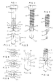
- a drill shaft 1 is shown in FIG. 1, which has a drive end 2 is provided with a hexagon head, e.g. serves in any Drive tool to be clamped.
- the lower part of the drill shaft 1 is shown in section, it contains the two grooves 3 and 4, which extends from the end face 5 of the drill shaft 1 in the direction extend to the hexagon head.
- the location and cross section of the grooves 3 and 4 can be seen from the end view according to FIG. 7, on the will be discussed in more detail below.
- the reasons 6 and 7 of the grooves 3 and 4 run over the essential Part of the length of the grooves 3 and 4 parallel to each other and parallel to the longitudinal axis of the drill shaft 1. They run in curves 8 and 9, which come here from the shape of a circular saw with which one can bring the grooves 3 and 4 into the drill shaft 1.
- the shape of the grooves 3 and 4 can also by others any methods are used, e.g. by pushing or pressing on what has already been pointed out above.
- the grooves 3 and 4 form the holder for that in FIGS. 2 and 3 illustrated drilling plate 10, which on its drilling side with the two Cutting edges 11 and 12 and on its cutting edges 11 and 12 Fork-shaped side with the two tines 13 and 14 is provided.
- the inner sides 15 and 16 of the two tines 13 and 14 run axially and parallel to each other and keep such a distance from each other, that the drilling plate is full on the between the can slide two grooves 3 and 4 stopped web 17, wherein due to an adjustment of the thickness of the drilling plate 10 to the width the grooves 3 and 4 or vice versa the prongs 13 and 14 with the Walls of grooves 3 and 4 come into contact.
- the tines 13 and 14 are so long that they are not in the Range of curves 8 and 9 extend so that for training the prongs 13 and 14 are only a space with parallel sides is to be produced. However, if the tines 13 and 14 continue into the Should protrude the area of the grooves 3 and 4, then if necessary Ends of the prongs 13 and 14 corresponding to curves 8 and 9 shape.
- FIG. 3 shows the side view of the drilling plate 10 according to FIG. 2, the is formed throughout with a constant thickness, that of the width the grooves 3 and 4 is adapted.
- a drilling plate can e.g. approx. 1 mm thick.
- Have holes to be drilled with such drilling platelets usually a diameter of up to approx. 5 mm.
- Drill plate 10 can be these two parts by pressing in Join the prongs 13 and 14 of the drilling plate 10 into the grooves 3 and 4, whereby the arrangement according to FIG. 4 arises, however compared to the drill shaft 1 shown smoothly in FIG. 1, the thread 18 carries, which is rolled to a corresponding diameter, with which then the screw shaft 19 shown in FIG. 4 is formed.
- the tines which here for the sake of better drawing on the side slightly over the outer diameter of the drill shaft 19
- FIG. 5 shows the arrangement according to FIG. 4 in a side view, from the clearly visible where the tines (here the tine 13) in the Grooves (here groove 3) end.
- FIG. 6 in which the screw shaft 19 with inserted drilling plate 10 from the side of the drilling plate is seen seen.
- the one to be transferred from the shaft 1 or 19 to the drilling plate 10 Torque is driven by the hexagon head 2 over the walls of the grooves 3 and 4 on the tines 13 and 14 pass, with which one Form and frictional connection results, the only grooves 3 and 4 and Tines 13 and 14 includes no other components.
- the tines 13 and 14 ensure the self-locking connection between Shank 1 or 19 and 10 drilling plate, so that the effect on the tines 13 and 14 the function of the self-locking connection and focused on torque transmission.
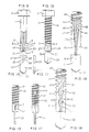
- FIG. 7 shows the drill shaft 1 in one Top view of the end face 5, namely without the drilling plate pressed in. From this it can be seen that the grooves 3 and 4 are rectangular Have cross-section, which is then when joining Drill shaft 1 and drill plate 10 of those not visible in FIG. 7 Tines 13 and 14 of the drilling plate 10 are filled in, whereby the self-locking connection between the drilling plate and Shaft is brought about.
- FIG. 8 shows a variant of the embodiment according to FIG. 7 shown, according to which the grooves 3 and 4 while increasing their Width are formed radially outwards.
- Grooves 3 and 4 accordingly have inclined walls 22 and 23 which the Cross section of the grooves 3 and 4 to a certain extent a wedge-shaped shape give, which causes a special pinching of the inserted in these grooves Tines are brought about.
- the inclined position of the walls 22 and 23 (and of course also the opposite walls) is in FIG. 8 exaggerated to clarify the illustration in the figure. In practice, it is only one of the straight line very slightly different inclination to make it a special one to achieve firm pinching.
- 9 to 12 is a variant of the embodiments according to 1 to 5, which is the grooves 3 and 4 to give a special design.
- That to this design of the holder of the drill shaft 1 matching drilling plate 26 is shown in FIGS. and side view (similar to the illustration in FIGS. 2 and 3).
- the drilling plate 26 has the two corresponding to the inclined position Reasons 24 and 25 correspondingly designed tines 27 and 28, their Insides 29 and 30 have essentially the same inclined position as reasons 24 and 25 of web 17.
- the drilling force occurring during drilling is in the embodiment 9 to 12 by the installation of the inner sides 29 and 30th the tines 27 and 28 caught against the grounds 24 and 25.
- the made of hard material drilling plate 26 can on the Normally absorb tines 27 and 28 applied forces. If however, particularly high drilling forces are to be transmitted, it can be useful be, also the embodiment according to FIGS. 9 to 12 with a To provide stop (similar to the effect of the end face 21 and the Throat 20 according to FIGS. 1 and 2).
- FIG. 13 A corresponding embodiment is shown in FIG. 13.
- the throat 33 contained here in the drilling plate 32 is essentially also provided with curves 34 and 35, but is between these two curves arranged the rounded projection 36, the serves when pressing the drilling plate 32 into the grooves 3 and 4 of the drill shaft 1 or the screw shaft 19 against the end face 21, which means particularly high drilling forces directly from the end face 21 can be transferred to the projection 36.
- the drilling plate 32 corresponds perfectly to this feature the drilling plate 26 according to FIGS. 10 and 11.
- FIG. 14 Another way of forming a stop is in FIG. 14 shown. This is formed here by the shoulders 37 and 38 from the material of the screw shaft 19 into the grooves 3 and 4 are pushed in. 14 keep the Shoulders 37 and 38 opposite ends of prongs 27 and 28 a small distance because in normal operation the strength the tines 27 and 28 are sufficient to withstand the drilling forces generated to catch up. However, if these drilling forces exceed a certain level, then the drilling plate 26 can continue into the grooves 3 and 4 push in until it ends with the ends of its tines 27 and 28 comes to rest on shoulders 37 and 38.
- FIG. 15 Another form of jamming between Drill plate and holder in the shaft is shown in FIG. 15.
- This shows the lower section of a screw shaft 19 with thread 18 and in its grooves 3 (not visible 4) inserted drilling plates 39.
- the figure shows that the width of the grooves 3 (and 4) in the direction reduced towards the drive end of the screw shaft 19, wherein the tines 27 (not visible 28) have the shape of the grooves 3 and 4 have adapted cross-section.
- the cross section of the grooves 3 and 4 and the tines 27 and 28 thus run like a wedge shape, with what when the tines 27 are pressed into the grooves 3 (not visible 28 and 4) strong wedging and thus self-locking of the tines 27 and 28 of the drilling plate 39 results.
- 16 is a connection of a screw shaft 40 with a Drill plate 41 shown, in which the thread 44 extends into the ends the tines 42 and 43 extend.
- the rolling tools also capture the Tines 42 and 43 and accordingly roll the thread 44 into them 16, so that the one shown in FIG. 16 follows the thread Longitudinal profile of the tines results.
- 16 is yet another special feature of the connection between the shaped shaft 40 and the drill plate 41.
- the tines 42 and 43 give way here to the screw shaft 40 End portion of the bottom of the grooves 45 and 46 back so that the gap 47 and 48 resulting from FIG. 16 between the inner sides the prongs 42 and 43 and the bases of the grooves 45 and 46 results. In this way it is achieved that the system of the tines 42 and 43 on the ends of the tines 42 facing the cutting edges 11 and 12 and 43 limited, whereby the result is that when the Boring plate 41 resulting spreading forces do not become too large.
- the method shown in connection with FIGS. 16 and 17 can also be used to roll the thread onto the ends of the tines take advantage of the drilling plate 53 through a special design its tines a special anchoring to the drill shaft 40 give. This is shown in FIG. 18.
- the tines 49 and 50 each have two recesses 51 and 52, into which material from the web 17 when rolling the thread 44 is pushed in. This results in a kind of entanglement between the tines 49 and 50 and the web 17 and thus opposite the Screw shaft 40.
Landscapes
- Engineering & Computer Science (AREA)
- General Engineering & Computer Science (AREA)
- Mechanical Engineering (AREA)
- Physics & Mathematics (AREA)
- Geometry (AREA)
- Drilling Tools (AREA)
- Soil Working Implements (AREA)
- Processing Of Stones Or Stones Resemblance Materials (AREA)
- Perforating, Stamping-Out Or Severing By Means Other Than Cutting (AREA)
- Earth Drilling (AREA)
Abstract
Description
- Fig. 1
- einen Bohrschaft mit einer im Schnitt gezeichneten Halterung für die Aufnahme eines Bohrplättchens mit parallel zueinander verlaufenden Zinken,
- Fig. 2
- das zu dem Bohrschaft gemäß Fig. 1 passende Bohrplättchen in einer Lage, aus der es in die Halterung des Bohrschaftes eingedrückt werden kann,
- Fig. 3
- das Bohrplättchen in Seitenansicht,
- Fig. 4
- den mit einem Gewinde versehenen Bohrschaft gemäß Fig. 1 zusammen mit dem Bohrplättchen gemäß Fig. 2,
- Fig. 5
- einen Ausschnitt aus der Darstellung gemäß Fig. 4 in einer Seitensicht,
- Fig. 6
- die Darstellung des Bohrers mit Schraubenschaft gemäß Fig. 4 mit axialer Blickrichtung auf die Schneiden des Bohrplättchens,
- Fig. 7
- einen Bohrschaft entsprechend der Darstellung gemäß Fig. 1 in gleicher Ansicht wie Fig. 6, allerdings ohne eingedrücktes Bohrplättchen mit Nuten mit rechteckförmigem Querschnitt,
- Fig. 8
- eine Abwandlung der Anordnung gemäß Fig. 7 mit Nuten mit etwa keilförmigem Querschnitt,
- Fig. 9
- einen Bohrschaft ähnlich der Darstellung gemäß Fig. 1 mit schräg verlaufenden Nuten,
- Fig. 10
- ein in den Bohrschaft gemäß Fig. 9 passendes Bohrplättchen,
- Fig. 11
- die Seitensicht des Bohrplättchens gemäß Fig. 10,
- Fig. 12
- einen Schraubenschaft entsprechend der Darstellung gemäß Fig. 9 mit eingedrücktem Bohrplättchen gemäß Fig. 10,
- Fig. 13
- ein Bohrplättchen ähnlich der Darstellung gemäß Fig. 10, und zwar mit einem Anschlag in der Kehle zwischen den Zinken,
- Fig. 14
- einen Ausschnitt aus einem Schraubenschaft mit eingedrücktem Bohrplättchen ähnlich der Anordnung gemäß Fig. 12, und zwar mit Anschlägen im Bereich der Nuten,
- Fig. 15
- eine Seitensicht eines Schraubenschaftes mit eingesetztem Bohrplättchen ähnlich der Darstellung gemäß Fig. 5, allerdings mit Nuten, deren Breite in Richtung zum Antriebsende hin sich verringert,
- Fig. 16
- einen Bohrschaft ähnlich der Darstellung gemäß Fig. 12 mit eingedrücktem Bohrplättchen, über dessen Zinken sich das Gewinde des Schraubenschaftes teilweise erstreckt,
- Fig. 17
- die Anordnung gemäß Fig. 16 in Seitensicht,
- Fig. 18
- eine Anordnung ähnlich der Fig. 16 mit inneren Ausnehmungen an den Zinken.
Claims (15)
- Bohrer mit einem Bohrschaft (1), insbesondere mit einem ein selbstfurchendes Gewinde (18) aufweisenden Schraubenschaft (19, 40), und einem dem Antriebsende (2) des Schaftes (1, 19, 40) gegenüberliegend angeordneten gabelförmigen Bohrplättchen (10, 26, 32, 39, 41, 53) aus hartem Material, das in eine Halterung im Schaft (1, 19, 40) eingesetzt ist, die zwei diametral zueinanderliegende Nuten (3, 4; 45, 46) im Schaft (1, 19, 40) zur Aufnahme von Zinken (13, 14; 27, 28; 42, 43; 49, 50) des Bohrplättchens (10, 26, 32, 39, 41, 53) aufweist, dessen Breite dem Durchmesser des Bohrschaftes (1) entspricht, dadurch gekennzeichnet, daß der Schaft (1, 19, 40) stumpf in einer im wesentlichen radial ebenen Abschlußfläche (5) endet, aus der die Nuten (3, 4; 45, 46) zum Antriebsende (2) hin derart verlaufen, daß allein die in die Nuten (3, 4; 45, 46) axial eingedrückten und in diesen satt sitzenden beiden Zinken (13, 14; 27, 28; 42, 43; 49, 50) des Bohrplättchens (10, 26, 32, 39, 41, 53) dieses selbsthemmend am Schaft (1, 19, 40) halten, und daß das Drehmoment vom Schaft (1, 19, 40) über die Wände der Nuten (3,4;45,46) auf beide Zinken (13,14; 27,28; 42,43; 49,50) übertragen wird.
- Bohrer nach Anspruch 1, dadurch gekennzeichnet, daß die Gründe (6, 7) der Nuten (3, 4) im Bereich ihrer Aufnahme der Zinken (13, 14) parallel zueinander verlaufen.
- Bohrer nach Anspruch 1, dadurch gekennzeichnet, daß die Nuten (3, 4) derart schräg zur Schaftachse in Richtung zum Antriebsende (2) mit derart zunehmendem Abstand ihrer Gründe (24, 25) verlaufen, daß die in die Nuten (3, 4) eingedrückten Zinken (27, 28) aufgrund der durch die Schräglage der Gründe (24, 25) auf die Zinken (27, 28) ausgeübten Spreizkraft in den Nuten (3, 4)selbsthemmend gehalten werden.
- Bohrer nach einem der Ansprüche 1 bis 3, dadurch gekennzeichnet, daß die Breite der Nuten (3, 4) so gewählt ist, daß die Zinken (13, 14) von den Wänden der Nuten (3, 4) eingeklemmt sind.
- Bohrer nach einem der Ansprüche 1 bis 4, dadurch gekennzeichnet, daß die Zinken (13, 14) unter Vorspannung an den Gründen (6, 7) der Nuten (3, 4) anliegen.
- Bohrer nach einem der Ansprüche 1 bis 5, dadurch gekennzeichnet, daß sich die Breite der Nuten (3, 4) radial nach außen vergrößert und die Zinken einen der Nutenform angepaßten Querschnitt aufweisen.
- Bohrer nach einem der Ansprüche 1 bis 6, dadurch gekennzeichnet, daß sich die Breite der Nuten (3, 4) in Richtung zum Antriebsende (2) verringert und die Zinken (27. 28) einen der Nutenform angepaßten Querschnitt aufweisen.
- Bohrer nach einem der Ansprüche 1 bis 7, dadurch gekennzeichnet, daß die radiale Anlage der Zinken (42, 43) an den Gründen bzw. Wänden der Nuten (45, 46) auf den Anfangsbereich der Zinken (42, 43) in der Nähe der Abschlußfläche (5) des Schaftes (40) beschränkt ist.
- Bohrer mit Schraubenschaft, dessen Gewinde kalt verformt, insbesondere gewalzt ist, nach einem der Ansprüche 1 bis 8, dadurch gekennzeichnet, daß sich die Nuten (45, 46) und die Zinken (42, 43) bis in das Gewinde (44) des Schraubenschaftes (40) erstrecken, wo das Längsprofil der Zinken (42, 43) dem Gewinde (44) folgt.
- Bohrer nach einem der Ansprüche 1 bis 9, dadurch gekennzeichnet, daß die Zinken (49, 50) auf ihrer dem Nutengrund zugewandten Seite mit Ausnehmungen (51, 52) versehen sind, in die bei einer Kaltverformung des Schraubenschaftes (40) verdrängtes Material eingedrückt ist.
- Bohrer nach einem der Ansprüche 1 bis 10, dadurch gekennzeichnet, daß zur Aufnahme einer axialen Bohrkraft ein Anschlag (37, 38) in einer Nut (3, 4) angeordnet ist.
- Bohrer nach einem der Ansprüche 1 bis 11, dadurch gekennzeichnet, daß die Zinken (27, 28) in einer Kehle (31) zusammenlaufen, die bei eingesetztem Bohrplättchen (26) einen Abstand von der Abschlußfläche (5) des Schaftes (1, 19) einhält.
- Bohrer nach einem der Ansprüche 1 bis 10, dadurch gekennzeichnet, daß die Zinken (27, 28) in einer Kehle (33) zusammenlaufen, die einen Anschlag (36) gegen die Abschlußfläche (21) des Schaftes (1, 19) zur Aufnahme einer axialen Bohrkraft bildet.
- Bohrer nach Anspruch 12 oder 13, dadurch gekennzeichnet, daß die Kehle (31) gerundet ausgebildet ist.
- Bohrer nach einem der Ansprüche 12 bis 14, dadurch gekennzeichnet, daß die Breite der Kehle (20, 31) kleiner ist als die Breite eines Zinkens (13, 14; 27, 28; 42, 43; 49, 50) im Bereich der Kehle.
Applications Claiming Priority (3)
| Application Number | Priority Date | Filing Date | Title |
|---|---|---|---|
| DE4410027 | 1994-03-23 | ||
| DE4410027A DE4410027A1 (de) | 1994-03-23 | 1994-03-23 | Bohrer, insbesondere Bohrschraube |
| PCT/EP1995/000841 WO1995025901A1 (de) | 1994-03-23 | 1995-03-07 | Bohrer, insbesondere bohrschraube |
Publications (2)
| Publication Number | Publication Date |
|---|---|
| EP0752068A1 EP0752068A1 (de) | 1997-01-08 |
| EP0752068B1 true EP0752068B1 (de) | 1998-10-07 |
Family
ID=6513625
Family Applications (1)
| Application Number | Title | Priority Date | Filing Date |
|---|---|---|---|
| EP95910561A Expired - Lifetime EP0752068B1 (de) | 1994-03-23 | 1995-03-07 | Bohrer, insbesondere bohrschraube |
Country Status (13)
| Country | Link |
|---|---|
| US (1) | US5749689A (de) |
| EP (1) | EP0752068B1 (de) |
| JP (1) | JPH10507246A (de) |
| KR (1) | KR970701838A (de) |
| CN (1) | CN1043677C (de) |
| AU (1) | AU1850795A (de) |
| BR (1) | BR9507151A (de) |
| CZ (1) | CZ275096A3 (de) |
| DE (2) | DE4410027A1 (de) |
| HU (1) | HUT74747A (de) |
| PL (1) | PL316312A1 (de) |
| TW (1) | TW272955B (de) |
| WO (1) | WO1995025901A1 (de) |
Families Citing this family (23)
| Publication number | Priority date | Publication date | Assignee | Title |
|---|---|---|---|---|
| DE4441716A1 (de) * | 1994-11-23 | 1996-05-30 | Ejot Verbindungstech Gmbh & Co | Selbstfurchende Schraube |
| US6296433B1 (en) | 2000-09-05 | 2001-10-02 | Illinois Tool Works Inc. | Large diameter tapcon with debris reservoir end or tip |
| DE10142560A1 (de) * | 2001-08-30 | 2003-03-20 | Hilti Ag | Bohrkopf mit einem Schneidelement |
| US6619899B1 (en) * | 2002-06-10 | 2003-09-16 | Power Products Iii, Llc | Cutting insert for fasteners |
| US20050117996A1 (en) * | 2003-12-02 | 2005-06-02 | Lemire Robert J. | Self-drilling fastener |
| US20060235415A1 (en) * | 2005-04-18 | 2006-10-19 | To-Ha Loi | Stainless self-tapping screw |
| US7686359B1 (en) * | 2006-04-03 | 2010-03-30 | Line Walker, LLC | Extraction tool |
| US20080008553A1 (en) * | 2006-07-10 | 2008-01-10 | Robert Andrew Gillis | Self-drilling anchor screw and method of using the same |
| EP2496166B1 (de) | 2009-11-05 | 2018-12-26 | Nimbus Concepts LLC | Systeme für wirbelsäulen-radiofrequenz-neurotomie |
| BR112012029263B8 (pt) | 2010-05-21 | 2022-08-16 | Nimbus Concepts Llc | Agulha de neurotomia por radiofrequência |
| DE102011053384A1 (de) * | 2011-09-08 | 2013-03-14 | Ejot Gmbh & Co. Kg | Verfahren zur Herstellung einer Schraube mit einem auf einen Dorn aufgesteckten hülsenförmigen Frontteil |
| US8882413B2 (en) | 2012-11-26 | 2014-11-11 | Iscar, Ltd. | Cutting tool and cutting insert with a rearward resilience slit |
| US10954988B2 (en) * | 2012-12-24 | 2021-03-23 | Shu-Chin Huang | Screw with flat drilling end |
| US20140178148A1 (en) * | 2012-12-24 | 2014-06-26 | Shu-Chin Huang | Flat drill end of a screw |
| AU2013200163B2 (en) * | 2013-01-14 | 2016-03-17 | Shu-Chin Huang | Flat drill end of a screw |
| FR3014726B1 (fr) * | 2013-12-18 | 2016-01-01 | Bollhoff Otalu Sa | Composant de fixation et assemblage auto perceur |
| DE102014204598A1 (de) * | 2014-03-12 | 2015-09-17 | Ejot Gmbh & Co. Kg | Zweistahlschraube mit Fließpressverbindung |
| BR112018003840B1 (pt) * | 2015-08-27 | 2022-09-06 | Ejot Baubefestigungen Gmbh | Parafuso perfurador e processo para a produção de um parafuso perfurador |
| CN109989978A (zh) * | 2018-01-02 | 2019-07-09 | 世铠精密股份有限公司 | 复合螺栓及其制造方法 |
| US10711820B2 (en) * | 2018-02-22 | 2020-07-14 | Shehkai Precision Co., Ltd. | Composite screw |
| PL3581319T3 (pl) | 2018-05-09 | 2024-07-08 | Brigham Young University | Układ i sposób spajania tarciowego za pomocą koronki tarciowej |
| US11692578B2 (en) * | 2018-09-26 | 2023-07-04 | Illinois Tool Works Inc. | Post-to-beam fastener |
| US12085108B2 (en) * | 2018-11-29 | 2024-09-10 | The Hillman Group, Inc. | Wallboard anchor |
Family Cites Families (14)
| Publication number | Priority date | Publication date | Assignee | Title |
|---|---|---|---|---|
| DE524677C (de) * | 1931-05-11 | Emil Kremer | Bohrer mit auswechselbaren Schneidmessern fuer Metallbearbeitung | |
| US2621548A (en) * | 1948-06-02 | 1952-12-16 | Warren W Williams | Mounting for cutting tools |
| DE1797505U (de) * | 1958-11-24 | 1959-10-08 | Odin Clorius As | Schraube. |
| US3715952A (en) * | 1969-09-19 | 1973-02-13 | Fischer Artur | Expansion anchor unit |
| DE2420191A1 (de) * | 1974-04-26 | 1975-11-13 | Krupp Gmbh | Bohrwerkzeug |
| US3859700A (en) * | 1974-05-07 | 1975-01-14 | Illinois Tool Works | Inserted blade cutter |
| DE2555647A1 (de) * | 1975-12-11 | 1977-06-16 | Jaeger Eberhard Gmbh | Bohrschraube |
| US4066379A (en) * | 1976-04-23 | 1978-01-03 | Prohaska Peter J H | Rotary tool assembly having removable working elements |
| AT350334B (de) * | 1977-01-19 | 1979-05-25 | Sfs Stadler Ag | Selbstbohrende schraube |
| AT369871B (de) * | 1980-09-30 | 1983-02-10 | Sfs Stadler Ag | Selbstbohrende schraube |
| DE4003375C1 (de) * | 1990-02-05 | 1991-05-23 | Sfs Stadler Holding Ag, Heerbrugg, Ch | |
| DE4003374C1 (de) * | 1990-02-05 | 1991-05-08 | Sfs Stadler Holding Ag, Heerbrugg, Ch | |
| US5184925A (en) * | 1992-01-10 | 1993-02-09 | Kennametal Inc. | Insert and insert support bar |
| DE4203949C2 (de) * | 1992-02-11 | 1996-06-05 | Sfs Ind Holding Ag | Selbstbohrender Befestiger |
-
1994
- 1994-03-23 DE DE4410027A patent/DE4410027A1/de not_active Withdrawn
-
1995
- 1995-03-07 EP EP95910561A patent/EP0752068B1/de not_active Expired - Lifetime
- 1995-03-07 PL PL95316312A patent/PL316312A1/xx unknown
- 1995-03-07 KR KR1019960705198A patent/KR970701838A/ko not_active Withdrawn
- 1995-03-07 US US08/704,769 patent/US5749689A/en not_active Expired - Fee Related
- 1995-03-07 DE DE59503857T patent/DE59503857D1/de not_active Expired - Fee Related
- 1995-03-07 HU HU9602501A patent/HUT74747A/hu unknown
- 1995-03-07 BR BR9507151A patent/BR9507151A/pt not_active Application Discontinuation
- 1995-03-07 WO PCT/EP1995/000841 patent/WO1995025901A1/de not_active Ceased
- 1995-03-07 CN CN95192206A patent/CN1043677C/zh not_active Expired - Fee Related
- 1995-03-07 JP JP7524335A patent/JPH10507246A/ja active Pending
- 1995-03-07 AU AU18507/95A patent/AU1850795A/en not_active Abandoned
- 1995-03-07 CZ CZ962750A patent/CZ275096A3/cs unknown
- 1995-03-18 TW TW084102642A patent/TW272955B/zh active
Also Published As
| Publication number | Publication date |
|---|---|
| DE4410027A1 (de) | 1995-09-28 |
| AU1850795A (en) | 1995-10-09 |
| MX9604233A (es) | 1998-05-31 |
| US5749689A (en) | 1998-05-12 |
| CZ275096A3 (en) | 1997-07-16 |
| HUT74747A (en) | 1997-02-28 |
| BR9507151A (pt) | 1997-09-02 |
| PL316312A1 (en) | 1997-01-06 |
| WO1995025901A1 (de) | 1995-09-28 |
| DE59503857D1 (de) | 1998-11-12 |
| TW272955B (en) | 1996-03-21 |
| KR970701838A (ko) | 1997-04-12 |
| HU9602501D0 (en) | 1996-11-28 |
| JPH10507246A (ja) | 1998-07-14 |
| CN1043677C (zh) | 1999-06-16 |
| CN1144555A (zh) | 1997-03-05 |
| EP0752068A1 (de) | 1997-01-08 |
Similar Documents
| Publication | Publication Date | Title |
|---|---|---|
| EP0752068B1 (de) | Bohrer, insbesondere bohrschraube | |
| DE2538139C2 (de) | Schraube | |
| DE2607338C2 (de) | Schlagdübel mit Spreizhülse und Spreizelement | |
| EP1531023B1 (de) | Bohrplatte welche klemmend in einem Grundkörper befestigt ist. | |
| DE1625417C3 (de) | Selbstbohrende und gewindeformende Schraube | |
| EP0466852B1 (de) | Selbstbohrender befestiger | |
| DE2216760C2 (de) | Gesteinsbohrer | |
| DE602004002611T2 (de) | Wanddübel für eine Schraube und die Anordnung, die durch solch einen Wanddübel und eine Schraube festgesetzt wird. | |
| EP3640487A1 (de) | Holzschraube mit bogenförmigem überstand zwischen gewindegängen | |
| EP0043000A1 (de) | Hinterschnitt-Bohrwerkzeug | |
| DE2917611C2 (de) | Dübel und Werkzeug zum Herstellen einer Bohrung für den Dübel | |
| DE3202280A1 (de) | Befestiger zum zusammensetzen von werkstuecken | |
| EP0292742A1 (de) | Distanzschraube | |
| DE3842683A1 (de) | Bohrvorrichtung zum herstellen von hinterschneidungen in nicht durchgehenden zylindrischen vorbohrungen und befestigungseinrichtung eines gewindebauteils in einer hinterschneidung | |
| DE2637350A1 (de) | Spreizduebel | |
| EP0947712B1 (de) | Spreizdübel | |
| DE3118691C2 (de) | ||
| EP0192914A1 (de) | Spreizdübel | |
| EP0605792B1 (de) | Oberflächenentwässerungseinrichtung | |
| DE2408625A1 (de) | Bohrer, besonders fuer schlagbohren | |
| DE4003375C1 (de) | ||
| DE4401908A1 (de) | Schraubbolzen | |
| DE4042399C1 (en) | Coupling sleeve between drill and drive shaft - has aperture retaining clamping stem head larger than sleeve bore | |
| EP0491153B1 (de) | Halter für einen Bohrer | |
| DE29705766U1 (de) | Seilverbindung für das Ende eines Drahtseils |
Legal Events
| Date | Code | Title | Description |
|---|---|---|---|
| PUAI | Public reference made under article 153(3) epc to a published international application that has entered the european phase |
Free format text: ORIGINAL CODE: 0009012 |
|
| 17P | Request for examination filed |
Effective date: 19961018 |
|
| AK | Designated contracting states |
Kind code of ref document: A1 Designated state(s): CH DE FR GB IT LI SE |
|
| GRAG | Despatch of communication of intention to grant |
Free format text: ORIGINAL CODE: EPIDOS AGRA |
|
| 17Q | First examination report despatched |
Effective date: 19980127 |
|
| GRAG | Despatch of communication of intention to grant |
Free format text: ORIGINAL CODE: EPIDOS AGRA |
|
| GRAH | Despatch of communication of intention to grant a patent |
Free format text: ORIGINAL CODE: EPIDOS IGRA |
|
| GRAH | Despatch of communication of intention to grant a patent |
Free format text: ORIGINAL CODE: EPIDOS IGRA |
|
| GRAA | (expected) grant |
Free format text: ORIGINAL CODE: 0009210 |
|
| AK | Designated contracting states |
Kind code of ref document: B1 Designated state(s): CH DE FR GB IT LI SE |
|
| REG | Reference to a national code |
Ref country code: CH Ref legal event code: NV Representative=s name: BRAUN & PARTNER PATENT-, MARKEN-, RECHTSANWAELTE Ref country code: CH Ref legal event code: EP |
|
| GBT | Gb: translation of ep patent filed (gb section 77(6)(a)/1977) |
Effective date: 19981008 |
|
| REF | Corresponds to: |
Ref document number: 59503857 Country of ref document: DE Date of ref document: 19981112 |
|
| ET | Fr: translation filed | ||
| PG25 | Lapsed in a contracting state [announced via postgrant information from national office to epo] |
Ref country code: SE Free format text: LAPSE BECAUSE OF NON-PAYMENT OF DUE FEES Effective date: 19990308 |
|
| PLBE | No opposition filed within time limit |
Free format text: ORIGINAL CODE: 0009261 |
|
| STAA | Information on the status of an ep patent application or granted ep patent |
Free format text: STATUS: NO OPPOSITION FILED WITHIN TIME LIMIT |
|
| 26N | No opposition filed | ||
| EUG | Se: european patent has lapsed |
Ref document number: 95910561.0 |
|
| EUG | Se: european patent has lapsed |
Ref document number: 95910561.0 |
|
| REG | Reference to a national code |
Ref country code: GB Ref legal event code: IF02 |
|
| PGFP | Annual fee paid to national office [announced via postgrant information from national office to epo] |
Ref country code: FR Payment date: 20020129 Year of fee payment: 8 |
|
| PGFP | Annual fee paid to national office [announced via postgrant information from national office to epo] |
Ref country code: GB Payment date: 20020211 Year of fee payment: 8 |
|
| PGFP | Annual fee paid to national office [announced via postgrant information from national office to epo] |
Ref country code: CH Payment date: 20020325 Year of fee payment: 8 |
|
| PG25 | Lapsed in a contracting state [announced via postgrant information from national office to epo] |
Ref country code: GB Free format text: LAPSE BECAUSE OF NON-PAYMENT OF DUE FEES Effective date: 20030307 |
|
| PG25 | Lapsed in a contracting state [announced via postgrant information from national office to epo] |
Ref country code: LI Free format text: LAPSE BECAUSE OF NON-PAYMENT OF DUE FEES Effective date: 20030331 Ref country code: CH Free format text: LAPSE BECAUSE OF NON-PAYMENT OF DUE FEES Effective date: 20030331 |
|
| GBPC | Gb: european patent ceased through non-payment of renewal fee |
Effective date: 20030307 |
|
| REG | Reference to a national code |
Ref country code: CH Ref legal event code: PL |
|
| PG25 | Lapsed in a contracting state [announced via postgrant information from national office to epo] |
Ref country code: FR Free format text: LAPSE BECAUSE OF NON-PAYMENT OF DUE FEES Effective date: 20031127 |
|
| REG | Reference to a national code |
Ref country code: FR Ref legal event code: ST |
|
| PG25 | Lapsed in a contracting state [announced via postgrant information from national office to epo] |
Ref country code: IT Free format text: LAPSE BECAUSE OF NON-PAYMENT OF DUE FEES Effective date: 20050307 |
|
| PGFP | Annual fee paid to national office [announced via postgrant information from national office to epo] |
Ref country code: DE Payment date: 20090313 Year of fee payment: 15 |
|
| PG25 | Lapsed in a contracting state [announced via postgrant information from national office to epo] |
Ref country code: DE Free format text: LAPSE BECAUSE OF NON-PAYMENT OF DUE FEES Effective date: 20101001 |