EP0747320A2 - Zusammensetzung zur Erzeugung eines phosphinhaltigen Gases - Google Patents
Zusammensetzung zur Erzeugung eines phosphinhaltigen Gases Download PDFInfo
- Publication number
- EP0747320A2 EP0747320A2 EP96108969A EP96108969A EP0747320A2 EP 0747320 A2 EP0747320 A2 EP 0747320A2 EP 96108969 A EP96108969 A EP 96108969A EP 96108969 A EP96108969 A EP 96108969A EP 0747320 A2 EP0747320 A2 EP 0747320A2
- Authority
- EP
- European Patent Office
- Prior art keywords
- metal phosphide
- phosphide
- phosphine
- metal
- composition
- Prior art date
- Legal status (The legal status is an assumption and is not a legal conclusion. Google has not performed a legal analysis and makes no representation as to the accuracy of the status listed.)
- Granted
Links
- XYFCBTPGUUZFHI-UHFFFAOYSA-N Phosphine Chemical compound P XYFCBTPGUUZFHI-UHFFFAOYSA-N 0.000 title claims abstract description 208
- 229910000073 phosphorus hydride Inorganic materials 0.000 title claims abstract description 107
- 239000000203 mixture Substances 0.000 title claims abstract description 101
- 229910052751 metal Inorganic materials 0.000 claims abstract description 138
- 239000002184 metal Substances 0.000 claims abstract description 138
- 239000007789 gas Substances 0.000 claims abstract description 105
- XLYOFNOQVPJJNP-UHFFFAOYSA-N water Substances O XLYOFNOQVPJJNP-UHFFFAOYSA-N 0.000 claims abstract description 90
- 238000000034 method Methods 0.000 claims abstract description 56
- 230000008569 process Effects 0.000 claims abstract description 51
- 238000006460 hydrolysis reaction Methods 0.000 claims abstract description 45
- 230000007062 hydrolysis Effects 0.000 claims abstract description 44
- 239000005953 Magnesium phosphide Substances 0.000 claims abstract description 35
- 239000002245 particle Substances 0.000 claims abstract description 31
- 239000000126 substance Substances 0.000 claims abstract description 23
- 238000006243 chemical reaction Methods 0.000 claims abstract description 18
- 230000002209 hydrophobic effect Effects 0.000 claims abstract description 18
- 239000000654 additive Substances 0.000 claims abstract description 17
- 238000000576 coating method Methods 0.000 claims abstract description 12
- 239000000428 dust Substances 0.000 claims abstract description 12
- 239000011777 magnesium Substances 0.000 claims abstract description 12
- FYYHWMGAXLPEAU-UHFFFAOYSA-N Magnesium Chemical compound [Mg] FYYHWMGAXLPEAU-UHFFFAOYSA-N 0.000 claims abstract description 11
- 239000000463 material Substances 0.000 claims abstract description 11
- 239000007788 liquid Substances 0.000 claims abstract description 10
- 229910052749 magnesium Inorganic materials 0.000 claims abstract description 10
- 239000003340 retarding agent Substances 0.000 claims abstract description 9
- 239000011261 inert gas Substances 0.000 claims abstract description 7
- 229910052782 aluminium Inorganic materials 0.000 claims abstract description 6
- OBSZRRSYVTXPNB-UHFFFAOYSA-N tetraphosphorus Chemical compound P12P3P1P32 OBSZRRSYVTXPNB-UHFFFAOYSA-N 0.000 claims abstract description 6
- 239000004411 aluminium Substances 0.000 claims abstract description 5
- XAGFODPZIPBFFR-UHFFFAOYSA-N aluminium Chemical compound [Al] XAGFODPZIPBFFR-UHFFFAOYSA-N 0.000 claims abstract description 5
- 239000011248 coating agent Substances 0.000 claims abstract description 5
- OYPRJOBELJOOCE-UHFFFAOYSA-N Calcium Chemical compound [Ca] OYPRJOBELJOOCE-UHFFFAOYSA-N 0.000 claims abstract description 4
- 239000011575 calcium Substances 0.000 claims abstract description 4
- 229910052791 calcium Inorganic materials 0.000 claims abstract description 4
- 239000003054 catalyst Substances 0.000 claims abstract description 3
- 238000004519 manufacturing process Methods 0.000 claims description 20
- 239000011236 particulate material Substances 0.000 claims description 15
- 239000005952 Aluminium phosphide Substances 0.000 claims description 8
- OAICVXFJPJFONN-UHFFFAOYSA-N Phosphorus Chemical compound [P] OAICVXFJPJFONN-UHFFFAOYSA-N 0.000 claims description 8
- PPNXXZIBFHTHDM-UHFFFAOYSA-N aluminium phosphide Chemical compound P#[Al] PPNXXZIBFHTHDM-UHFFFAOYSA-N 0.000 claims description 8
- 229910052698 phosphorus Inorganic materials 0.000 claims description 8
- 239000011574 phosphorus Substances 0.000 claims description 8
- 239000008187 granular material Substances 0.000 claims description 7
- 239000007787 solid Substances 0.000 claims description 7
- VURFVHCLMJOLKN-UHFFFAOYSA-N diphosphane Chemical compound PP VURFVHCLMJOLKN-UHFFFAOYSA-N 0.000 claims description 6
- 230000002708 enhancing effect Effects 0.000 claims description 6
- PGYDGBCATBINCB-UHFFFAOYSA-N 4-diethoxyphosphoryl-n,n-dimethylaniline Chemical compound CCOP(=O)(OCC)C1=CC=C(N(C)C)C=C1 PGYDGBCATBINCB-UHFFFAOYSA-N 0.000 claims description 5
- 239000006009 Calcium phosphide Substances 0.000 claims description 5
- OKTJSMMVPCPJKN-UHFFFAOYSA-N Carbon Chemical compound [C] OKTJSMMVPCPJKN-UHFFFAOYSA-N 0.000 claims description 5
- 150000003003 phosphines Chemical class 0.000 claims description 5
- 229910002804 graphite Inorganic materials 0.000 claims description 4
- 239000010439 graphite Substances 0.000 claims description 4
- 239000012535 impurity Substances 0.000 claims description 4
- 238000002844 melting Methods 0.000 claims description 4
- 230000008018 melting Effects 0.000 claims description 4
- 239000007795 chemical reaction product Substances 0.000 claims description 3
- 239000001257 hydrogen Substances 0.000 claims description 3
- 229910052739 hydrogen Inorganic materials 0.000 claims description 3
- QGZKDVFQNNGYKY-UHFFFAOYSA-O Ammonium Chemical compound [NH4+] QGZKDVFQNNGYKY-UHFFFAOYSA-O 0.000 claims description 2
- WKBOTKDWSSQWDR-UHFFFAOYSA-N Bromine atom Chemical compound [Br] WKBOTKDWSSQWDR-UHFFFAOYSA-N 0.000 claims description 2
- ZAMOUSCENKQFHK-UHFFFAOYSA-N Chlorine atom Chemical compound [Cl] ZAMOUSCENKQFHK-UHFFFAOYSA-N 0.000 claims description 2
- NINIDFKCEFEMDL-UHFFFAOYSA-N Sulfur Chemical compound [S] NINIDFKCEFEMDL-UHFFFAOYSA-N 0.000 claims description 2
- 239000005864 Sulphur Substances 0.000 claims description 2
- HCHKCACWOHOZIP-UHFFFAOYSA-N Zinc Chemical compound [Zn] HCHKCACWOHOZIP-UHFFFAOYSA-N 0.000 claims description 2
- GDTBXPJZTBHREO-UHFFFAOYSA-N bromine Substances BrBr GDTBXPJZTBHREO-UHFFFAOYSA-N 0.000 claims description 2
- 229910052794 bromium Inorganic materials 0.000 claims description 2
- 239000000460 chlorine Substances 0.000 claims description 2
- 229910052801 chlorine Inorganic materials 0.000 claims description 2
- PNDPGZBMCMUPRI-UHFFFAOYSA-N iodine Chemical class II PNDPGZBMCMUPRI-UHFFFAOYSA-N 0.000 claims description 2
- 150000002739 metals Chemical class 0.000 claims description 2
- 238000004806 packaging method and process Methods 0.000 claims description 2
- 229910052725 zinc Inorganic materials 0.000 claims description 2
- 239000011701 zinc Substances 0.000 claims description 2
- 125000004435 hydrogen atom Chemical class [H]* 0.000 claims 1
- 239000012159 carrier gas Substances 0.000 abstract description 32
- 238000003958 fumigation Methods 0.000 abstract description 26
- 238000002156 mixing Methods 0.000 abstract description 20
- 239000003085 diluting agent Substances 0.000 abstract description 5
- CURLTUGMZLYLDI-UHFFFAOYSA-N Carbon dioxide Chemical compound O=C=O CURLTUGMZLYLDI-UHFFFAOYSA-N 0.000 description 14
- 239000000843 powder Substances 0.000 description 14
- 238000003860 storage Methods 0.000 description 13
- 239000000356 contaminant Substances 0.000 description 9
- VEXZGXHMUGYJMC-UHFFFAOYSA-N Hydrochloric acid Chemical compound Cl VEXZGXHMUGYJMC-UHFFFAOYSA-N 0.000 description 8
- 239000000047 product Substances 0.000 description 8
- 239000001569 carbon dioxide Substances 0.000 description 7
- 229910002092 carbon dioxide Inorganic materials 0.000 description 7
- 238000005406 washing Methods 0.000 description 7
- XKRFYHLGVUSROY-UHFFFAOYSA-N Argon Chemical compound [Ar] XKRFYHLGVUSROY-UHFFFAOYSA-N 0.000 description 6
- 239000010802 sludge Substances 0.000 description 6
- 235000013339 cereals Nutrition 0.000 description 5
- 238000012544 monitoring process Methods 0.000 description 5
- 239000012188 paraffin wax Substances 0.000 description 5
- 230000009257 reactivity Effects 0.000 description 5
- 238000012360 testing method Methods 0.000 description 5
- 230000000007 visual effect Effects 0.000 description 5
- IJGRMHOSHXDMSA-UHFFFAOYSA-N Atomic nitrogen Chemical compound N#N IJGRMHOSHXDMSA-UHFFFAOYSA-N 0.000 description 4
- 230000008901 benefit Effects 0.000 description 4
- 238000004140 cleaning Methods 0.000 description 4
- 238000010586 diagram Methods 0.000 description 4
- 239000013505 freshwater Substances 0.000 description 4
- 210000002445 nipple Anatomy 0.000 description 4
- 238000012856 packing Methods 0.000 description 4
- 239000008188 pellet Substances 0.000 description 4
- 239000003380 propellant Substances 0.000 description 4
- 241000607479 Yersinia pestis Species 0.000 description 3
- 229910052786 argon Inorganic materials 0.000 description 3
- 230000015572 biosynthetic process Effects 0.000 description 3
- 230000005587 bubbling Effects 0.000 description 3
- 238000011109 contamination Methods 0.000 description 3
- 238000010790 dilution Methods 0.000 description 3
- 239000012895 dilution Substances 0.000 description 3
- 230000000694 effects Effects 0.000 description 3
- 239000001307 helium Substances 0.000 description 3
- 229910052734 helium Inorganic materials 0.000 description 3
- SWQJXJOGLNCZEY-UHFFFAOYSA-N helium atom Chemical compound [He] SWQJXJOGLNCZEY-UHFFFAOYSA-N 0.000 description 3
- 238000003825 pressing Methods 0.000 description 3
- 230000002035 prolonged effect Effects 0.000 description 3
- 230000001105 regulatory effect Effects 0.000 description 3
- 238000007789 sealing Methods 0.000 description 3
- QGZKDVFQNNGYKY-UHFFFAOYSA-N Ammonia Chemical compound N QGZKDVFQNNGYKY-UHFFFAOYSA-N 0.000 description 2
- 229920000742 Cotton Polymers 0.000 description 2
- 241001465754 Metazoa Species 0.000 description 2
- 229910019440 Mg(OH) Inorganic materials 0.000 description 2
- ATUOYWHBWRKTHZ-UHFFFAOYSA-N Propane Chemical compound CCC ATUOYWHBWRKTHZ-UHFFFAOYSA-N 0.000 description 2
- 230000035508 accumulation Effects 0.000 description 2
- 238000009825 accumulation Methods 0.000 description 2
- 238000013019 agitation Methods 0.000 description 2
- GZUXJHMPEANEGY-UHFFFAOYSA-N bromomethane Chemical compound BrC GZUXJHMPEANEGY-UHFFFAOYSA-N 0.000 description 2
- 238000001816 cooling Methods 0.000 description 2
- 238000004880 explosion Methods 0.000 description 2
- 239000012530 fluid Substances 0.000 description 2
- 239000002316 fumigant Substances 0.000 description 2
- 238000010438 heat treatment Methods 0.000 description 2
- 238000005470 impregnation Methods 0.000 description 2
- 230000006872 improvement Effects 0.000 description 2
- ZLNQQNXFFQJAID-UHFFFAOYSA-L magnesium carbonate Chemical compound [Mg+2].[O-]C([O-])=O ZLNQQNXFFQJAID-UHFFFAOYSA-L 0.000 description 2
- 239000001095 magnesium carbonate Substances 0.000 description 2
- 229910000021 magnesium carbonate Inorganic materials 0.000 description 2
- VTHJTEIRLNZDEV-UHFFFAOYSA-L magnesium dihydroxide Chemical compound [OH-].[OH-].[Mg+2] VTHJTEIRLNZDEV-UHFFFAOYSA-L 0.000 description 2
- 239000000347 magnesium hydroxide Substances 0.000 description 2
- 229910001862 magnesium hydroxide Inorganic materials 0.000 description 2
- 230000007246 mechanism Effects 0.000 description 2
- VNWKTOKETHGBQD-UHFFFAOYSA-N methane Chemical compound C VNWKTOKETHGBQD-UHFFFAOYSA-N 0.000 description 2
- 238000003801 milling Methods 0.000 description 2
- 238000012986 modification Methods 0.000 description 2
- 230000004048 modification Effects 0.000 description 2
- 229910052757 nitrogen Inorganic materials 0.000 description 2
- 150000003018 phosphorus compounds Chemical class 0.000 description 2
- 239000004065 semiconductor Substances 0.000 description 2
- 238000005496 tempering Methods 0.000 description 2
- 231100000331 toxic Toxicity 0.000 description 2
- 230000002588 toxic effect Effects 0.000 description 2
- 239000005997 Calcium carbide Substances 0.000 description 1
- 239000004215 Carbon black (E152) Substances 0.000 description 1
- BVKZGUZCCUSVTD-UHFFFAOYSA-L Carbonate Chemical compound [O-]C([O-])=O BVKZGUZCCUSVTD-UHFFFAOYSA-L 0.000 description 1
- 235000019733 Fish meal Nutrition 0.000 description 1
- 244000068988 Glycine max Species 0.000 description 1
- 235000010469 Glycine max Nutrition 0.000 description 1
- 229920004449 Halon® Polymers 0.000 description 1
- 241000238631 Hexapoda Species 0.000 description 1
- UFHFLCQGNIYNRP-UHFFFAOYSA-N Hydrogen Chemical compound [H][H] UFHFLCQGNIYNRP-UHFFFAOYSA-N 0.000 description 1
- 235000014647 Lens culinaris subsp culinaris Nutrition 0.000 description 1
- 244000043158 Lens esculenta Species 0.000 description 1
- 235000010627 Phaseolus vulgaris Nutrition 0.000 description 1
- 244000046052 Phaseolus vulgaris Species 0.000 description 1
- 240000004713 Pisum sativum Species 0.000 description 1
- 235000010582 Pisum sativum Nutrition 0.000 description 1
- 241000533293 Sesbania emerus Species 0.000 description 1
- 244000269722 Thea sinensis Species 0.000 description 1
- 230000002378 acidificating effect Effects 0.000 description 1
- 230000009471 action Effects 0.000 description 1
- HSFWRNGVRCDJHI-UHFFFAOYSA-N alpha-acetylene Natural products C#C HSFWRNGVRCDJHI-UHFFFAOYSA-N 0.000 description 1
- 150000001398 aluminium Chemical class 0.000 description 1
- 229910021529 ammonia Inorganic materials 0.000 description 1
- 238000004458 analytical method Methods 0.000 description 1
- 239000011230 binding agent Substances 0.000 description 1
- 230000000903 blocking effect Effects 0.000 description 1
- 238000009835 boiling Methods 0.000 description 1
- 229940036811 bone meal Drugs 0.000 description 1
- 239000002374 bone meal Substances 0.000 description 1
- 239000001273 butane Substances 0.000 description 1
- 238000004891 communication Methods 0.000 description 1
- 150000001875 compounds Chemical class 0.000 description 1
- 235000009508 confectionery Nutrition 0.000 description 1
- 230000002950 deficient Effects 0.000 description 1
- 230000003111 delayed effect Effects 0.000 description 1
- 238000013461 design Methods 0.000 description 1
- 238000011161 development Methods 0.000 description 1
- PXBRQCKWGAHEHS-UHFFFAOYSA-N dichlorodifluoromethane Chemical compound FC(F)(Cl)Cl PXBRQCKWGAHEHS-UHFFFAOYSA-N 0.000 description 1
- 235000011869 dried fruits Nutrition 0.000 description 1
- 239000000839 emulsion Substances 0.000 description 1
- 238000005516 engineering process Methods 0.000 description 1
- 230000007613 environmental effect Effects 0.000 description 1
- 125000002534 ethynyl group Chemical group [H]C#C* 0.000 description 1
- 239000002360 explosive Substances 0.000 description 1
- 239000012467 final product Substances 0.000 description 1
- 239000004467 fishmeal Substances 0.000 description 1
- 239000011888 foil Substances 0.000 description 1
- 235000011868 grain product Nutrition 0.000 description 1
- IXCSERBJSXMMFS-UHFFFAOYSA-N hcl hcl Chemical compound Cl.Cl IXCSERBJSXMMFS-UHFFFAOYSA-N 0.000 description 1
- 229930195733 hydrocarbon Natural products 0.000 description 1
- 150000002430 hydrocarbons Chemical class 0.000 description 1
- 150000002431 hydrogen Chemical class 0.000 description 1
- 238000010348 incorporation Methods 0.000 description 1
- 238000012423 maintenance Methods 0.000 description 1
- 150000004692 metal hydroxides Chemical group 0.000 description 1
- 229940102396 methyl bromide Drugs 0.000 description 1
- 238000012806 monitoring device Methods 0.000 description 1
- IJDNQMDRQITEOD-UHFFFAOYSA-N n-butane Chemical compound CCCC IJDNQMDRQITEOD-UHFFFAOYSA-N 0.000 description 1
- OFBQJSOFQDEBGM-UHFFFAOYSA-N n-pentane Natural products CCCCC OFBQJSOFQDEBGM-UHFFFAOYSA-N 0.000 description 1
- 235000012149 noodles Nutrition 0.000 description 1
- 235000019198 oils Nutrition 0.000 description 1
- 238000005192 partition Methods 0.000 description 1
- 235000015927 pasta Nutrition 0.000 description 1
- 239000004033 plastic Substances 0.000 description 1
- 229920003023 plastic Polymers 0.000 description 1
- 239000002244 precipitate Substances 0.000 description 1
- 238000002360 preparation method Methods 0.000 description 1
- 239000001294 propane Substances 0.000 description 1
- 238000003908 quality control method Methods 0.000 description 1
- 239000000376 reactant Substances 0.000 description 1
- 239000011541 reaction mixture Substances 0.000 description 1
- 238000009877 rendering Methods 0.000 description 1
- 238000011160 research Methods 0.000 description 1
- 239000011369 resultant mixture Substances 0.000 description 1
- 230000000979 retarding effect Effects 0.000 description 1
- 230000000630 rising effect Effects 0.000 description 1
- 238000000926 separation method Methods 0.000 description 1
- 235000013599 spices Nutrition 0.000 description 1
- 239000007858 starting material Substances 0.000 description 1
- CLZWAWBPWVRRGI-UHFFFAOYSA-N tert-butyl 2-[2-[2-[2-[bis[2-[(2-methylpropan-2-yl)oxy]-2-oxoethyl]amino]-5-bromophenoxy]ethoxy]-4-methyl-n-[2-[(2-methylpropan-2-yl)oxy]-2-oxoethyl]anilino]acetate Chemical compound CC1=CC=C(N(CC(=O)OC(C)(C)C)CC(=O)OC(C)(C)C)C(OCCOC=2C(=CC=C(Br)C=2)N(CC(=O)OC(C)(C)C)CC(=O)OC(C)(C)C)=C1 CLZWAWBPWVRRGI-UHFFFAOYSA-N 0.000 description 1
- 238000012546 transfer Methods 0.000 description 1
- 238000011144 upstream manufacturing Methods 0.000 description 1
- 235000013311 vegetables Nutrition 0.000 description 1
- 238000013022 venting Methods 0.000 description 1
- 239000002699 waste material Substances 0.000 description 1
- 239000002351 wastewater Substances 0.000 description 1
- 239000002023 wood Substances 0.000 description 1
Images

Classifications
-
- A—HUMAN NECESSITIES
- A23—FOODS OR FOODSTUFFS; TREATMENT THEREOF, NOT COVERED BY OTHER CLASSES
- A23B—PRESERVATION OF FOODS, FOODSTUFFS OR NON-ALCOHOLIC BEVERAGES; CHEMICAL RIPENING OF FRUIT OR VEGETABLES
- A23B2/00—Preservation of foods or foodstuffs, in general
- A23B2/70—Preservation of foods or foodstuffs, in general by treatment with chemicals
- A23B2/704—Preservation of foods or foodstuffs, in general by treatment with chemicals in the form of gases, e.g. fumigation; Compositions or apparatus therefor
-
- A—HUMAN NECESSITIES
- A23—FOODS OR FOODSTUFFS; TREATMENT THEREOF, NOT COVERED BY OTHER CLASSES
- A23B—PRESERVATION OF FOODS, FOODSTUFFS OR NON-ALCOHOLIC BEVERAGES; CHEMICAL RIPENING OF FRUIT OR VEGETABLES
- A23B2/00—Preservation of foods or foodstuffs, in general
- A23B2/70—Preservation of foods or foodstuffs, in general by treatment with chemicals
- A23B2/725—Preservation of foods or foodstuffs, in general by treatment with chemicals in the form of liquids or solids
- A23B2/788—Inorganic compounds
-
- A—HUMAN NECESSITIES
- A23—FOODS OR FOODSTUFFS; TREATMENT THEREOF, NOT COVERED BY OTHER CLASSES
- A23B—PRESERVATION OF FOODS, FOODSTUFFS OR NON-ALCOHOLIC BEVERAGES; CHEMICAL RIPENING OF FRUIT OR VEGETABLES
- A23B9/00—Preservation of edible seeds, e.g. cereals
- A23B9/16—Preserving with chemicals
- A23B9/18—Preserving with chemicals in the form of gases, e.g. fumigation; Compositions or apparatus therefor
-
- B—PERFORMING OPERATIONS; TRANSPORTING
- B01—PHYSICAL OR CHEMICAL PROCESSES OR APPARATUS IN GENERAL
- B01J—CHEMICAL OR PHYSICAL PROCESSES, e.g. CATALYSIS OR COLLOID CHEMISTRY; THEIR RELEVANT APPARATUS
- B01J4/00—Feed or outlet devices; Feed or outlet control devices
-
- B—PERFORMING OPERATIONS; TRANSPORTING
- B01—PHYSICAL OR CHEMICAL PROCESSES OR APPARATUS IN GENERAL
- B01J—CHEMICAL OR PHYSICAL PROCESSES, e.g. CATALYSIS OR COLLOID CHEMISTRY; THEIR RELEVANT APPARATUS
- B01J7/00—Apparatus for generating gases
- B01J7/02—Apparatus for generating gases by wet methods
-
- C—CHEMISTRY; METALLURGY
- C01—INORGANIC CHEMISTRY
- C01B—NON-METALLIC ELEMENTS; COMPOUNDS THEREOF; METALLOIDS OR COMPOUNDS THEREOF NOT COVERED BY SUBCLASS C01C
- C01B25/00—Phosphorus; Compounds thereof
- C01B25/06—Hydrogen phosphides
-
- C—CHEMISTRY; METALLURGY
- C01—INORGANIC CHEMISTRY
- C01B—NON-METALLIC ELEMENTS; COMPOUNDS THEREOF; METALLOIDS OR COMPOUNDS THEREOF NOT COVERED BY SUBCLASS C01C
- C01B25/00—Phosphorus; Compounds thereof
- C01B25/08—Other phosphides
- C01B25/081—Other phosphides of alkali metals, alkaline-earth metals or magnesium
-
- C—CHEMISTRY; METALLURGY
- C01—INORGANIC CHEMISTRY
- C01B—NON-METALLIC ELEMENTS; COMPOUNDS THEREOF; METALLOIDS OR COMPOUNDS THEREOF NOT COVERED BY SUBCLASS C01C
- C01B25/00—Phosphorus; Compounds thereof
- C01B25/08—Other phosphides
- C01B25/082—Other phosphides of boron, aluminium, gallium or indium
- C01B25/085—Other phosphides of boron, aluminium, gallium or indium of aluminium
-
- Y—GENERAL TAGGING OF NEW TECHNOLOGICAL DEVELOPMENTS; GENERAL TAGGING OF CROSS-SECTIONAL TECHNOLOGIES SPANNING OVER SEVERAL SECTIONS OF THE IPC; TECHNICAL SUBJECTS COVERED BY FORMER USPC CROSS-REFERENCE ART COLLECTIONS [XRACs] AND DIGESTS
- Y02—TECHNOLOGIES OR APPLICATIONS FOR MITIGATION OR ADAPTATION AGAINST CLIMATE CHANGE
- Y02P—CLIMATE CHANGE MITIGATION TECHNOLOGIES IN THE PRODUCTION OR PROCESSING OF GOODS
- Y02P20/00—Technologies relating to chemical industry
- Y02P20/141—Feedstock
- Y02P20/145—Feedstock the feedstock being materials of biological origin
Definitions
- the present invention relates to a metal phosphide composition for the production of phosphine by hydrolysis, comprising solid particles of metal phosphide selected from the group consisting of magnesium phosphide, aluminium phosphide and calcium phosphide and mixtures of these, more particularly presented in a form ready for use in a process and in a phosphine generator for generating a mixture of phosphine and diluent gas or gases, wherein such a hydrolysable metal phosphide is contacted with liquid water in a generating space, whereby the metal phosphide is hydrolysed to release phosphine which is withdrawn from the generating space and, where applicable, diluted from the time of its generation to its reaching its locality of use with a diluent gas to a composition which is non-ignitable under the conditions of use.
- the invention also relates to the use of the metal phosphide composition in such process and/or generator.
- Phosphine gas is a highly toxic and flammable gas used in large quantities in pest control, and in particular for the fumigation of agricultural bulk commodities, such as grain and grain products. Phosphine gas generation is also subject to some peculiarities giving rise to special problems which do not apply to the generation by hydrolysis of other gases, e.g. the well-known generation of acetylene gas by hydrolysis of calcium carbide as disclosed e.g. in British patent specifications 472 970 (Haworth), 776,070 (Union Carbide) and 291,997 (Haworth).
- compositions containing hydrolysable metal phosphides, in particular aluminium, magnesium and calcium phosphides have been used for this purpose, applied either in sachets or other dispenser devices or as moulded bodies (pellets or tablets).
- compositions are apportioned in sachets, bag-blankets, bag-chains or similar dispensers, the purpose is to divide the composition into small individual portions in order to reduce the hazards of large local accumulations of gas and heat build up and at the same time prevent direct contact of the compositions with the commodities.
- These devices must, after completion of the fumigation, be retrieved from the storage or like facility where the fumigation has taken place. This is often difficult and cumbersome. The spent devices must then be disposed of, a matter which nowadays may cause problems.
- US Patent 5,098,664 discloses a recent attempt to overcome the prejudice existing in the art against the generation of phosphine gas in an external generator apparatus, wherein relatively large concentrated batches of metal phosphide are hydrolysed by the passage therethrough of controlled amounts of water vapour dispersed in humid air, the air serving as a carrier gas.
- This proposal still suffers from certain potential shortcomings. That disclosure teaches interrupting the hydrolysis in the event of operational failures by displacing the humid air in the generator space by an inert fluid, (liquid or gas).
- magnesium hydroxide continues to react with not yet hydrolysed magnesium phosphide as follows: 3 Mg(OH) 2 + Mg 3 P 2 ⁇ 2PH 3 + 6 MgO
- prior art tablets are dropped periodically one by one at a controlled rate into a water bath inside a generating space.
- the compositions being in the form of compressed bodies, namely tablets, are specially compounded to reduce their reactivity. These tablets take a relatively long time to decompose when dropped into water, even if the water is heated, as proposed in this prior art. Accordingly this prior art process and apparatus suffers from the drawback that the gas generation is relatively slow and can only be accelerated by increasing the rate of feeding tablets into the water.
- the amount of metal phosphide submerged in the water bath at any one time is relatively large, and accordingly, if it becomes necessary to stop the gas generation because of some operational failure, it will take a long time before the gas generation stops, and large volumes of phosphine gas are generated during that period which have to be disposed of in some way or another.
- the phosphine is released into air and the risk of ignitable mixtures of phosphine and air being formed cannot be excluded.
- the gases released by such prior art composition when dropped into water have a greater or lesser tendency to autoignite.
- compositions used in that process release paraffin wax or other hydrophobic and other additives into the water bath.
- the hydrophobic contaminants in particular float on the water surface and interfere with the smooth progress of the process by forming emulsions and entrapping metal phosphide particles and generally contaminate the water in the apparatus and the apparatus itself, causing a disposal and cleaning problem.
- These problems also arise from the proposals in PCT application WO 93 25075 wherein an extrudable paste of the metal phosphide and a water-immiscible, grease-like substance is squeezed into water in a generator space.
- This material has, in the past, invariably been phlegmatised immediately after its formation by impregnation and coating with a hydrophobic substance, preferably hard paraffin in amounts of about 1 to 4 %, preferably 2 to 3,5 %, before any further handling or before storage prior to use in the manufacture of compositions for pest control purposes, such as the aforesaid "plates".
- a hydrophobic substance preferably hard paraffin in amounts of about 1 to 4 %, preferably 2 to 3,5 %
- the present invention now provides a metal phosphide composition as set out in the opening paragraph, comprising the feature that it is presented in a form ready for use in a hydrolysis process performed in a generator and is in the form of a free-flowing particulate metal phosphide material composed of loose particles of said metal phosphide essentially free of metal phosphide dust, essentially free of hydrolysis retarding agents and essentially free of hydrophobic substances in the form of coatings or hydrophobising additives.
- the present invention had to overcome several serious prejudices existing in the art, based on problems real or conceived.
- the invention when used as herein disclosed, can provide a number of safety features which each, taken alone constitute a great improvement over the prior art and which are preferably used in combination.
- a metal phosphide composition for the production of phosphine by hydrolysis comprising solid particles of metal phosphide selected from the group consisting of aluminium phosphide, calcium phosphide and magnesium phosphide and mixtures of these, free of impurities, which on hydrolysis liberate autoignitable phosphine homologues, phosphine derivatives, organophosphines, diphosphine or polyphosphines, in the form of a free-flowing powder essentially free-of metal phosphide dust, essentially free of hydrolysis retarding agents and essentially free of hydrophobic substance in the form of coatings or additives, which surprisingly can be used to produce phosphine gas safely by exposure to liquid water in the manner described further below.
- the phosphine formed is free of autoigniting contaminants, and the gas mixture formed was found to have no tendency to autoignite, even when released into air in such amounts that the concentration of the phosphine in air exceeds the ignition limit as known for mixtures of air and phosphine.
- a carrier gas is selected which is inert to the phosphine and preferably non-flammable, the gas mixture as such is quite safe.
- the particles contain more than 90%, preferably not less than 95% by weight pure metal phosphide.
- the composition may include a substance enhancing the free-flowing characteristics, which, however, should not be hydrophobic, at least not to any material extent.
- the substance enhancing free-flowing characteristics is graphite dust in an amount of from about 0,1 % by weight upwards, preferably up to 0,5% by weight.
- the preferred metal phosphide is essentially magnesium phosphide, more particularly produced from magnesium and yellow phosphorus at a temperature of from 350 to 550°C, throughout the reaction batch and more specifically in the manufacture of which care is taken that the temperature nowhere exceeds from 450 to 550°C.
- the reaction mixture at the end of the main reaction is subjected to tempering treatment at 530 - 550°C, preferably substantially at 550°C (i.e. just below the melting point of the phosphide) of 20 minutes to 3 hours, preferably about 1 hour in order for any unreacted phosphorus to become wholly reacted.
- tempering treatment at 530 - 550°C, preferably substantially at 550°C (i.e. just below the melting point of the phosphide) of 20 minutes to 3 hours, preferably about 1 hour in order for any unreacted phosphorus to become wholly reacted.
- the prior art metal phosphide e.g. as produced in accordance with the aforesaid references, is always, in normal conventional manufacture, impregnated with a hydrophobic substance, usually about 3,5% molten paraffin wax, immediately after leaving the reactor and whilst still hot, in order to reduce the reactivity of the metal phosphide and render it safer to handle, or so it was believed.
- a hydrophobic substance usually about 3,5% molten paraffin wax
- the preferred composition is composed of particles of which more than 90% by weight are in the particle size range of from 0,1 to 2,5 mm, preferably elongate particles having a length of about 0,8 - 1,4 mm and a thickness in the range of 0,1 - 0,3, say 0,2 mm. More particularly the manufacture is so controlled that the particles are composed of magnesium phosphide granules as directly formed in the magnesium phosphide production process, i.e. from magnesium particles having substantially the same particle dimensions. This offers the advantage that no milling is necessary which, apart from the costs and wear and tear involved, would give rise to undesirable dust formation.
- the composition is preferably sealed in a gastight dispenser container and preferably the gastight container contains an atmosphere of carrier gas inert to the metal phosphide. More particularly the container has a connection locality designed to be connected to a phosphine generator and said connection locality includes a region which, when opened, and after having been connected, releases the composition into the generator. Preferably the interior of the container tapers towards the said region in a funnel-like manner.
- the metal phosphide in contrast to all prior art metal phosphide compositions, in particular pest control compositions, does not have to contain the usual additives, helps to avoid the introduction of moisture into the container which conventionally gives rise to undesirable phosphine release during storage. Accordingly the compositions according to the invention have excellent storage characteristics.
- the metal phosphide composition may be used in a process, wherein the metal phosphide is released into liquid water in a free-flowing particulate form, composed of loose metal phosphide particles, essentially free of metal phosphide dust and of hydrolysis retarding agents and essentially free of hydrophobic substance in the form of coatings or hydrophobising additives, and, in the event that dilution commences already in the generating space, under an atmosphere comprising a carrier gas inert to the phosphine, forming at least part of the diluent gas.
- dilution commences already in the generating space and the carrier gas inert to the phosphine is also inert to the metal phosphide and the metal phosphide is maintained in an atmosphere of said carrier gas before entering the water.
- An advantageous feature is that the particulate metal phosphide released into the water, because of its small particle size, high reactivity and the absence of reaction retarding additives, in particular an absence of hydrophobic coatings, sinks in the water, becomes wholly submerged and hydrolyses almost immediately, and in any event in less than 3 minutes, preferably less than 1 minute. Indeed, using magnesium phosphide, the hydrolysis is normally complete within a few seconds.
- the rate of hydrolysis is preferably accelerated by acidifying the water, e.g. with 5 % HC l or rendering it alkaline. This may be preferred to heating the water as disclosed in the aforesaid PCT application WO 91/19671.
- cooling and/or recirculation of the water may sometimes be resorted to, to prevent undesirable rises in temperature. The reason is that at high temperature the water evaporates more rapidly, sometimes resulting in an undesirable moisture content of the generated gas mixture.
- the temperature of the water is preferably maintained at below 60°C. More preferably the temperature of the water is regulated to from 3 to 40°C.
- the water is also agitated with the carrier gas.
- the process is preferably carried out with the above-described embodiment of the metal phosphide composition which is sealed in a gastight dispenser container.
- the metal phosphide powder of the composition after having been discharged from the container is entrained in the carrier gas and thus entrained is carried into the generator space and there enters into the water.
- the contents of the dispenser container are introduced into the water in from 30 minutes to 30 hours.
- the nature of the carrier gas as well as the ratio of phosphine to carrier gas can be selected within wide limits to suit a desired purpose.
- a convenient upper limit has been about 75 % v/v phosphine gas.
- the metal phosphide composition may, for example, be introduced into the water at a rate adapted to the rate of admission of carrier gas and the rate of withdrawal of the mixture to produce said mixture in a ratio of from about 40:60 to 3:95 by volume of phosphine : carrier gas.
- said ratio is from 30:60 to 5:93, more particularly from 17:82 to 10:90, e.g. 13:87.
- a ratio of not more than 8:92 is preferred, because such mixture will no longer support a flame in an ordinary air atmosphere.
- the carrier gas is preferably non-flammable.
- the carrier gas inert to phosphine is selected from the group consisting of CO 2 , argon, helium, nitrogen, ammonia, methylbromide, freon and halon gases and mixtures of two or more of these.
- nitrogen or CO 2 particularly the latter, are particularly preferred, inter alia because CO 2 synergistically enhances the effectiveness of PH 3 as a fumigant.
- CO 2 in the process according to the invention offers the further advantage that it accelerates the hydrolysis of the metal phosphide.
- carrier gases heavier than air may be used.
- carrier gases may, for example, include hydrocarbon gases heavier than air such as propane and butane and their isomers.
- a gas lighter than air such as helium, methane or hydrogen may be employed, although in the latter two cases special precautions against fire and explosion hazards need to be taken, so that helium is generally preferred.
- the phosphine produced in accordance with the invention may be so pure that it can be used for semiconductor doping.
- the preferred carrier gas is argon.
- great savings of inert gas may be achieved and risks of operating with high concentrations of phosphine gas may be further reduced, in that the mixture of phosphine gas and carrier gas inert to phosphine, withdrawn from the generator space, is mixed with air in a ratio of phosphine to air below the ignition limit of phosphine in a mixing space isolated from the environment and upstream of a feed duct for the mixture.
- the mixing space is preferably temperature monitored, so that the admission of phosphine gas to the mixing space may be interrupted, preferably automatically in the event of a predetermined temperature limit being exceeded.
- water from the generator space is withdrawn and forwarded into an aerating space and air is bubbled through the water in the aerating space and from there is forwarded into the mixing space and mixed there with the phosphine gas and, where applicable, the mixture of phosphine gas and carrier gas inert to phosphine to form said non-ignitable mixture.
- the air is withdrawn from a closed fumigation space wherein fumigation is to take place and the non-ignitable mixture is fed into the fumigation space.
- the gas mixture may be introduced into a fumigating space containing a commodity to be fumigated with phosphine, where the phosphine is diluted by the atmosphere in that space to suitable concentration levels.
- the gas in the fumigating space, including the mixture is recirculated.
- the commodity is a bulk commodity and the gas recirculation is performed through the bulk commodity.
- the bulk commodity is a heaped particulate agricultural or forestry commodity.
- the bulk commodity is a commodity selected from the group consisting of grain, beans, peas, lentils, oil seeds, soya beans, nuts, coffee beans, tea, any of the aforegoing in comminuted, granulated, pelleted or flaked form, milling products of agricultural commodities, particulate or pelleted animal feeds, wood in a particulate form, animal or fish meal, bone meal, bark in a particulate form, cotton, cotton lint, dried fruit, dehydrated vegetables, spices, sago, farinaceous products and confectionery.
- the gas mixture may also be employed in the so-called SIROFLOW process, developed by the CSIRO in Australia.
- SIROFLOW so-called SIROFLOW process
- RG Winks "The Effect of Phosphine on Resistant Insects", GASGA Seminar on Fumigation Technology, Tropical Development and Research Institute, Storage Department, Slough 18-21 March, 1986 and RG Winks "Flow-Trough Phosphine Fumigation - A New Technique", Stored Grain Protection Conference, 1983 Section 5.1; WO 91/00017 (CSIRO)).
- This invention has also been found to be very useful for space fumigation, e.g. of storage sheds, but in particular of grain mills and factories e.g. for the manufacture of farinaceous products, e.g. noodles and other kinds of pasta.
- the mixture of phosphine and carrier gas which preferably consists of inert gas, e.g.
- CO 2 used in carrying out the hydrolysis with liquid water diluted with air to attain a phosphine concentration not exceeding 2,4 % v/v, a concentration of about 18000 ppm (parts per million) being preferred, is introduced from the generator into the space and distributed there by piping, preferably including an appropriate number and configuration of branch pipes leading to various parts, and where applicable different levels of the space(s) to be fumigated.
- a phosphine generator which comprises a phosphine generating chamber containing liquid water, optionally and preferably an inlet connected or adapted to be connected to a supply of a gas inert to phosphine and for introducing an atmosphere of said gas into the phosphine generating chamber, an inlet for admitting a hydrolysable metal phosphide composition into the water in the generating chamber, a gas outlet adapted to discharge the phosphine and, where applicable, a mixture of the phosphine and gas inert thereto from the generating chamber and feed means adapted for feeding the metal phosphide through the inlet at a controlled rate, characterized in that the feed means is adapted to feed said metal phosphide in a free-flowing particulate form, composed of loose metal phosphide particles.
- This generator is designed to use the free-flowing metal phosphide composition according to the invention.
- the invention also provides a process for the manufacture of a metal phosphide composition according to the invention which comprises reacting a finely divided metal, selected from the group consisting of aluminium, calcium and magnesium with yellow phosphorus in an inert gas atmosphere and in the presence of a catalyst, selected from the group consisting of chlorine, bromine, iodine, compounds of any of the aforegoing with one of phosphorus, sulphur, hydrogen, zinc, ammonium and the aforesaid metals and of water at a temperature between 300 and 600°C, characterized in that throughout the reaction batch and throughout the process, once reacting has commenced, said temperature is maintained within the range of 350°C to 550°C, that the metal phosphide is withdrawn as a particulate free-flowing material and is packaged ready for use in phosphine generation in such free-flowing condition, essentially free of dust, essentially free of hydrolysis retarding agents and essentially free of hydrophobising substance in the form of coating or hydrophobis
- the metal is magnesium.
- said temperature is nowhere outside the range of 450 to 550°C.
- the metal is employed with a particle size of from 0,1 to 2,5 mm and the particulate metal phosphide produced has essentially the same particle size.
- the reaction product is maintained just below its melting point of about 550°C, for a period of 20 minutes to 3 hours and residual traces of unreacted phosphorus are removed.
- the particulate metal phosphide is mixed with about 0,1 to 0,5% by weight of graphite or other suitable non-hydrophobic substance enhancing the free-flowing characteristics.
- the metal phosphide being substantially additive-free, decomposes substantially entirely, leaving behind only a harmless metal hydroxide residue which by the CO 2 is converted into carbonate in the form of an environmentally harmless sludge, which can be drawn off from time to time.
- Magnesium phosphide for use in the process and apparatus was produced by the method in accordance with US Patents 4,331,642, 4,412,979, GB application 2062602 and GB application 2097775 at a temperature between 450 and 550°C, great care being taken that nowhere in the reactor a temperature of 550°C was exceeded.
- Extremely pure magnesium powder having a particle size ranging from 0,1 to 2 mm was employed as the starting material and the resulting magnesium phosphide formed in the reactor in the form of a granulate having the same particle size. This granulate, after having been discharged from the reactor, was maintained at 550°C for a further 1 hour to cause residual traces of unconverted phosphorus to be converted as well.
- the metal phosphide composition is then filled into and sealed in a container as descrsibed with reference to Fig. 2 of the drawings.
- Aluminium phosphide and calcium phosphide are produced in substantially analogous manner.
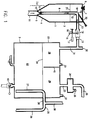
- the apparatus may be considered as comprising basically two parts.
- an apparatus 1 for feeding at a controlled rate a free-flowing particulate material, namely in the present instance the free-flowing metal phosphide material.
- the gas generator vessel proper generally denoted as 2.
- this includes a gastight closed supply vessel 3, the bottom 4 of which is funnel-shaped, terminating in an apex 5 and which contains a bed of particulate material.
- the top 6 of the supply vessel includes a feed inlet 7, closable in a gastight manner.
- a riser tube 8 is provided inside the supply vessel, starting from close to the apex 5 and rising vertically near the centre line of the vessel, a riser tube 8 is provided, its lower end near the apex 5 being open at its inlet region through apertures 9 to the supply vessel and facing a venturi nozzle 10 which is vertically upwardly directed into the riser tube 8 and forms the end of a propellant gas supply tube 11 passing through the apex 5 and leading to a propellant gas supply, not shown, for example a carbon dioxide bottle.
- a propellant gas supply tube 11 passing through the apex 5 and leading to a propellant gas supply, not shown, for example a carbon dioxide bottle.
- the inlet region is immersed in the bed of particulate material.
- the riser tube Shortly underneath the top 6 of the supply vessel the riser tube has a bend 12, leading by way of a duct 13 through the side wall of the supply vessel outside the latter.
- the duct 13 can be opened or closed by a valve or gate which in the present example is a ball valve 14 having an operating lever 15.
- the lever 15 is biased to the closed position by, for example, a spring 16.
- the spring 16 will automatically return the valve 14 to its closed position, thereby sealing off the supply vessel 1 from the continuation of the duct 13.
- valve means 14, 15, 16, 17 may be replaced by an electromagnetic valve device.
- an upwardly directed aperture 18 is provided on the upwardly facing side of the bend 12, at the beginning of the bend, in the outer periphery thereof, and in axial alignment with the riser tube 8, an upwardly directed aperture 18 is provided.
- Aperture 18 may be of fixed size but is preferably adjustable by means of an adjustment gate 19, operable by an adjustment screw 20 passing through the top 6 of the supply vessel. Aperture 18 enters the gas space of the supply vessel, i.e. above the level of the bed of particulate material.
- the venturi nozzle 10 is formed by a screw threaded insert screwed into the bottom spigot 5' to which the gas supply tube 11 is connected.
- the gas supply tube 11 is represented by a gas hose connector nipple 11' entering sideways into the tubular member 11'' welded at one end in axial alignment to the bottom spigot 5'.
- the opposite end terminates in a sliding seal 201 through which passes a needle valve needle 202, the tip 203 of which, in the closed position, as shown in the drawing, passes through and closes the venturi nozzle 10.
- the far end of the needle 202 is pivotally connected, diagrammatically shown at 204, to an operating lever 205, pivotally supported at 206 and having an operating handle 207. Movement of the handle in the direction of arrow 208 causes the withdrawal of the needle tip from the nozzle 10 and opening of the needle valve.
- the manual lever may be replaced by a pneumatically or electromagnetically operating mechanism which may optionally be programmed to operate automatically.
- the apparatus 1 operates as follows:
- An amount of free-flowing particulate material, a powder or granulate, is charged into the supply vessel 3 through the inlet 7.
- the inlet is appropriately closed in sealing relationship after the powder has been introduced, for example up to a level 21.
- the carrier gas supply is then opened to admit gas pressure to the carrier gas duct 11 and the device 17 which causes the valve 14 to open.
- the venturi effect of the nozzle 10 causes particulate material to be drawn into the riser tube 8 through the apertures 9 to be entrained in the riser tube and carried upwards. If the aperture 18 were to be completely closed, all the entrained particulate material would be carried through the bend and through the duct 13.
- the particulate material is a metal phosphide powder or granulate, e.g. magnesium phosphide, no humidity can enter the vessel 3 from the outside and the magnesium phosphide remains completely protected against atmospheric hydrolysis.
- the apparatus is equipped with a needle valve 10, 202, as shown in Fig. 1a, that needle valve is normally kept closed when the feeder device 1 is not in operation.
- the needle valve is opened prior to the admission of gas pressure to the gas supply duct 11. If the carrier gas is inert to the particulate material and the particulate material is to be kept under an inert atmosphere, the needle valve is opened prior to introducing the particulate material in order to flush the supply vessel 3 with inert gas admitted through the gas supply duct 11.
- the generator vessel 2 comprises a closed vessel 22 wherein a supply of water 23 is maintained up to a level 24 by supplying water through water supply spigot 25 up to the level 24 which is dictated by the water overflow device 26 which includes a drainage tube 27 leading from near the bottom of the vessel 22 to a pipe bend 28 leading horizontally outside through the side wall of the vessel 22 at a level which determines the water level 24 and leading into a downwardly directed drainpipe 29.
- the water overflow device 26 which includes a drainage tube 27 leading from near the bottom of the vessel 22 to a pipe bend 28 leading horizontally outside through the side wall of the vessel 22 at a level which determines the water level 24 and leading into a downwardly directed drainpipe 29.
- an upwardly directed vent pipe 30 is provided on the pipe bend 28.
- a gas outlet pipe 33 passes from the top of the vessel 22 through a droplet separator 34 into an outlet duct 35 through which the gas mixture generated in the generator is forwarded to wherever the gas is required, e.g. a silo, the contents of which are to be fumigated.
- a pipe nipple 36 on the droplet separator 34 serves for the withdrawal of gas samples for analysis.
- a further pipe nipple 37 on the righthand side of the top of the vessel 22 leads to a pressure monitoring device (not shown).
- the gas space 38, 39 above the water surface 24 in the top part of the vessel 22 is subdivided into two chambers 38 and 39 by a vertical partition 40 extending from the top of the vessel down to the water surface and physically separates the entry for the metal phosphide powder supplied by ducts 31, 13 from the exit region for the generated gas through the duct 33.
- a vertical partition 40 extending from the top of the vessel down to the water surface and physically separates the entry for the metal phosphide powder supplied by ducts 31, 13 from the exit region for the generated gas through the duct 33.
- an inlet duct 41 for carrier gas preferably CO 2
- a valve controlled water and sludge drainage spigot 42 is provided in the bottom of the vessel 22 at its lowest point.
- the apparatus functions as follows. Before the start of phosphine generation CO 2 is bubbled through the duct 41 to displace any air from the apparatus. Once this has happened feeding of particulate metal phosphide material, preferably very pure magnesium phosphide may commence from the feed device 1 through the duct 13, 31 into chamber 38 from where the magnesium phosphide particles drop into the water 23 and are almost instantly hydrolysed. Agitation by the continued admission of CO 2 through duct 41 continues and further CO 2 is admitted to the vessel 22 through the duct 31 together with the magnesium phosphide powder.
- particulate metal phosphide material preferably very pure magnesium phosphide may commence from the feed device 1 through the duct 13, 31 into chamber 38 from where the magnesium phosphide particles drop into the water 23 and are almost instantly hydrolysed. Agitation by the continued admission of CO 2 through duct 41 continues and further CO 2 is admitted to the vessel 22 through the duct 31 together with the magnesium phosphide powder.
- the resultant mixture of phosphine generated in the vessel and carbon dioxide admitted through ducts 31, 41 is so regulated that a desired ratio of phosphine to carbon dioxide accumulates in chamber 39 and is discharged through the outlet means 33, 34, 35.
- a desired ratio of phosphine to carbon dioxide accumulates in chamber 39 and is discharged through the outlet means 33, 34, 35.
- the overflowing water and sludge may be drained into a clarifying vessel, from where water, after the sludge has largely settled out, may be returned through a cooling system back to the water feed spigot 25.
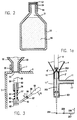
- a metal phosphide composition according to the invention 50 in an atmosphere 51 of the carrier gas CO 2 sealed in a gastight dispenser container in the form of an aluminium flask 52 of a size sufficiently large to hold a standardised quantity of the free-flowing magnesium phosphide composition 50.
- a gastight dispenser container in the form of an aluminium flask 52 of a size sufficiently large to hold a standardised quantity of the free-flowing magnesium phosphide composition 50.
- flasks holding, for example amounts of 1 kg, 2 kg and 5 kg respectively of the metal phosphide composition.
- the mouth of the flask is sealed with a gastight seal of aluminum foil 53 which is protected by a screw cap 54 screwed onto the threaded neck 55 of the flask.
- the screw threaded neck 55 of the flask 52 matches the internal thread and size of the inlet spigot 7 in the top 6 of the supply vessel 3 of the apparatus shown in Fig. 1.
- the flask 52 is shown screwed tightly into the spigot 7 at a stage when the seal 53 is still intact.
- a seal perforating device Inside the supply vessel there is mounted a seal perforating device, by the operation of which the seal 53 may be cut open. It includes a bush 56 in which is slidably mounted a plunger 57 carrying at its far end, upwardly directed and facing the seal 53, a punch bit 58 having sharp edges 59 similar to the punch bits of an office paper punch.
- the shoulder 60 rests on the upper edge of the bush 56, being biased into that position by a spring 61 between the lower edge of the bush 56 and a flange 62 near the bottom end of the plunger 57.
- the plunger 57 is engaged by the prongs of a fork-shaped end 64 of a lever arm 65 mounted irrotationally on a horizontal shaft 66 passing through the side wall of the supply vessel 3 in pivotal and sealing relationship, provided by a bush 67.
- a second lever arm 68 terminating in a handle 69 is irrotationally mounted on the shaft 66.
- the dimensions and design are so chosen that the punched out disk cannot interfere with the operation of the apparatus, e.g. by blocking the apertures 9.
- the apparatus is now ready for use. Once the contents of the flask 52 have been consumed, and if more metal phosphide is needed, the flask 52 may be screwed off, and a further flask may be screwed in place with a slight positive carbon dioxide pressure prevailing in the supply vessel so that no moisture can enter from the atmosphere. The seal is then again punched open.
- argon can be used as a carrier gas instead of CO 2 .
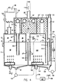
- the main difference resides in that the gas outlet pipe 33 leading from the gas space 39 above the water level 24 of the hydrolysis chamber 22 and the droplet separation chamber containing water disentrainment means 34 (any suitable packing for that purpose) is adjoined by and communicates with a gas mixing chamber 100 through a duct 35'.
- the mixing chamber is likewise packed with a water disentrainment packing 34'.
- the water collected in the packing 34 drains back into the water bath 23 through a draining pipe 101 extending well below the water level 24.
- any water collected in the mixing chamber 100 drains into a cavity 26' extending from the mixing chamber to near the bottom of the hydrolysis chamber 22 and separating in conjunction with an overflow weir 102 the water bath 23 from the water 103 in the aerating chamber 104.
- the overflow weir 102 extends up to the water level 24 and divides the cavity 26' into water inflow cavity 27' and outflow cavity 29' which communicate above the overflow weir 102 through the overflow and venting chamber 30' (28').
- an air distributor and bubbling device 105 is provided, connected to a source of air formed by an air duct 106, an air blower 107 and an air suction duct 108 connected to a fumigation space (109).
- An air space 110 above the water 103 in the aerating chamber discharges thereabove through a discharge duct 111 into a disentrainment chamber 112, containing a droplet separator packing 34'' and communicating with the gas mixing chamber 100 through an air passage 113.
- the mixing chamber has a gas mixture outlet 35'' connected by a feed duct 114 to the fumigation space (109) not shown as such.
- the aerating vessel 104 on its side opposite the overflow weir 102 and associated walls 27' and 29' is bordered by a similar overflow structure. This is formed by a wall 115 extending from the top of air chamber 110 down to near the bottom 116 of the aerating chamber, an overflow weir 117 and an overflow passage 118 leading into an outlet chamber 119 and outlet duct 120.
- the top of the outlet chamber 119 forms an air space 121 with a vent duct 122.
- the bottom of the hydrolysis chamber 22 slopes towards a drainage spigot 42 connected to a drainage pump 123.
- the bottom of the aerating chamber 104 slopes towards a draining spigot 124 connected to a drainage pump 125.
- the outlet duct 120 is connected to a drainage pump 126.
- 128 represents a feed tank for cleaning fluid (HC l ) which is introduced at the end of a generating cycle (or after 10 kg of magnesium phosphide have been consumed). Its contents are discharged through a hose 129 into the generator chamber 22 to assist the cleaning water to wash out solid precipitates of magnesium carbonate. 130 is a pressure equalisation hose.
- the air blower 107 can also be employed to apply recirculation of the mixture of phosphine and air and/or other diluent gas (e.g. CO 2 ) through a heaped bulk commodity (e.g. a particulate agricultural or forestry commodity) contained in the fumigating space (e.g. a silo or shiphold), e.g. in the manner known from the above-cited prior art.
- a heaped bulk commodity e.g. a particulate agricultural or forestry commodity contained in the fumigating space
- thermal switch 127 in the mixing chamber connected to switch off the supply of metal phosphide to the hydrolysis chamber from the feed device (1) and thereby, within seconds interrupting the supply of further phosphine in the event of an excessive temperature (more than 100°C) in the mixing chamber indicating fire or fire risk.
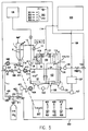
- FIG. 5 there is shown diagrammatically the apparatus in accordance with Figure 4 and its control means within the confines of a cabinet, diagrammatically indicated by the outlines 200.
- the apparatus is connected on the inlet side to a carbon dioxide bottle 210.
- water feed pipe 25 is connected to an outside source of fresh water, not shown.
- the space to be fumigated is diagrammatically shown by block-shaped outlines 109.
- the waste water outlet 120 leads to a drain or collecting vessel outside the apparatus.
- the cabinet has an electronic mode control panel 300 with four control buttons, a start button 301, a pause button 302, a restart button 303 and a washing mode button 304, each one adjoined by a pilot light 310 to indicate the particular operating mode which has been set.
- a general on/off switch is diagrammatically indicated as 311. Further, there is diagrammatically indicated a manual and visual flow control panel 400 on which is mounted the control lever 207 in accordance with Figure 1a and which includes manual flow regulating valves 401, 405 and 409 each associated with a visual flow indicator 402, 406 and 410 respectively. The functions of these will be explained in what follows.
- the CO 2 bottle 210 is connected by a gas hose 211 to a manifold 212, one arm of which leads into the CO 2 inlet duct 41, leading into the gas bubbling device at the bottom of the generator chamber 23.
- This duct includes the manual control valve 401 and the visual flow indicator 402 on the panel 400, an electronic flow monitor 403 and an electronically controlled regulator valve 404.
- Duct 11 includes the manual regulator valve 405 and visual flow indicator 406 of panel 400, an electronic flow monitor 407 and an electronically controlled regulator valve 408.
- the fresh water inlet 25 feeding water into the generator chamber 23 includes a manual flow control valve 409 and visual flow rate indicator 410 on panel 400 and an electronic flow monitor 411 and electronically controlled regulator flow valve 412. It furthermore optionally includes a fresh water temperature gauge 414, which serves for information only and has no control function.
- the wall temperature gauge 413 in the top part 38 of the generator vessel is purely for information purposes as is the water temperature gauge 415 inside the water bath of the generator chamber 23.
- the water level monitor 416 in the generator chamber is connected to the automatic electronic control means of the apparatus for automatic corrective action in the event of the water level 24 deviating from normal.
- the flow rate of air in the air duct 106, leading into the aerating chamber 103 of the generator, drawn through duct 108 from the fumigation space 109 by the blower 107 is automatically electronically monitored by the gas flow rate monitor 417.
- a further electronic gas flow rate monitor 418 is provided in the duct 33 leading from the generator gas space 39 into the water disentrainment chamber preceding the mixing chamber 100.
- the apparatus is programmed to operate fully automatically and the operator need only press the appropriate button on the panel 300.
- First the start button 301 is operated. This causes the water, CO 2 and air feeds and water pump 126 to be switched on. If the electronic monitoring means indicate that all four critical parameters are in order, the apparatus runs for about seven minutes as a pre-preparationary period, until the correct water level 24 has been attained. If in this respect any operational fault is detected, the apparatus is switched automatically to "pause" mode and an alarm is sounded. If everything is in order, the electronically controlled valves for CO 2 and magnesium phosphide are opened in the coupe of a period of about thirty seconds.
- the process can be interrupted at will by pressing the "pause” button 302, to be restarted if desired by pressing the "restart” button 303.
- the CO 2 valves and the electronically controlled valves for CO 2 and metal phosphide are automatically closed and the washing phase commences.
- the vessel 128 at a preprogrammed stage receives an appropriate volume of hydrochloric acid which is admitted to the generator space 24 where it mixes with washing water which is withdrawn by pump 123 and forwarded into the aerating chamber 103 from where in turn it is forwarded by pump 125 into the outlet chamber 119, 121 from where it is finally withdrawn by pump 126 and discharged through duct 120.
- the washing programme can also be started at will by pressing the "washing" button 304.
- the sub-headings of the vertical columns (t) represent the times in minutes for the various product phases (where x is variable).
- Aluminium phosphide can be used if the temperature of the water bath is preferably at least 60°C and if 5% HC l is added.
- the above apparatus was found to offer considerable advantages over the prior art. Because of the free-flowing nature of the metal phosphide it is possible to feed the metal phosphide accurately at the desired rate and in a form wherein it is hydrolysed and releases phosphine almost immediately.
- the feed means is completely isolated from moisture and before the metal phosphide enters the phosphine generating chamber it is maintained in a completely inert, moisture-free environment. The moment the propellant gas supply is interrupted - intentionally or otherwise - the feeding of metal phosphide composition is interrupted and the metal phosphide inside the feed device is isolated from the generating space.
Landscapes
- Chemical & Material Sciences (AREA)
- Organic Chemistry (AREA)
- Life Sciences & Earth Sciences (AREA)
- Engineering & Computer Science (AREA)
- Inorganic Chemistry (AREA)
- Zoology (AREA)
- Polymers & Plastics (AREA)
- Chemical Kinetics & Catalysis (AREA)
- Food Science & Technology (AREA)
- Wood Science & Technology (AREA)
- General Life Sciences & Earth Sciences (AREA)
- Geology (AREA)
- Environmental & Geological Engineering (AREA)
- General Chemical & Material Sciences (AREA)
- Agricultural Chemicals And Associated Chemicals (AREA)
- Catching Or Destruction (AREA)
- Physical Or Chemical Processes And Apparatus (AREA)
- Organic Low-Molecular-Weight Compounds And Preparation Thereof (AREA)
- Manufacture Of Metal Powder And Suspensions Thereof (AREA)
- Catalysts (AREA)
Applications Claiming Priority (2)
| Application Number | Priority Date | Filing Date | Title |
|---|---|---|---|
| GB9511495 | 1995-06-07 | ||
| GBGB9511495.5A GB9511495D0 (en) | 1995-06-07 | 1995-06-07 | Composition, process and apparatus for producing phosphine - containing gas |
Publications (3)
| Publication Number | Publication Date |
|---|---|
| EP0747320A2 true EP0747320A2 (de) | 1996-12-11 |
| EP0747320A3 EP0747320A3 (de) | 1997-02-26 |
| EP0747320B1 EP0747320B1 (de) | 2008-08-06 |
Family
ID=10775648
Family Applications (2)
| Application Number | Title | Priority Date | Filing Date |
|---|---|---|---|
| EP96109145A Expired - Lifetime EP0747319B1 (de) | 1995-06-07 | 1996-06-05 | Verfahren und Vorrichtung zur Erzeugung eines phosphinhaltigen Gases |
| EP96108969A Expired - Lifetime EP0747320B1 (de) | 1995-06-07 | 1996-06-05 | Zusammensetzung zur Erzeugung eines phosphinhaltigen Gases |
Family Applications Before (1)
| Application Number | Title | Priority Date | Filing Date |
|---|---|---|---|
| EP96109145A Expired - Lifetime EP0747319B1 (de) | 1995-06-07 | 1996-06-05 | Verfahren und Vorrichtung zur Erzeugung eines phosphinhaltigen Gases |
Country Status (19)
| Country | Link |
|---|---|
| US (3) | US6027667A (de) |
| EP (2) | EP0747319B1 (de) |
| JP (1) | JP4282776B2 (de) |
| CN (2) | CN1163408C (de) |
| AR (2) | AR002386A1 (de) |
| AT (2) | ATE403629T1 (de) |
| AU (2) | AU712536B2 (de) |
| BR (2) | BR9602718A (de) |
| CA (2) | CA2178545C (de) |
| DE (2) | DE69638039D1 (de) |
| DK (1) | DK0747319T3 (de) |
| ES (2) | ES2333920T3 (de) |
| GB (1) | GB9511495D0 (de) |
| IL (1) | IL118592A (de) |
| MX (2) | MX9602168A (de) |
| PT (1) | PT747319E (de) |
| RU (1) | RU2238905C2 (de) |
| UA (1) | UA49798C2 (de) |
| ZA (1) | ZA964713B (de) |
Cited By (1)
| Publication number | Priority date | Publication date | Assignee | Title |
|---|---|---|---|---|
| CN110097989A (zh) * | 2018-01-31 | 2019-08-06 | 中国辐射防护研究院 | 一种用于球床高温气冷堆的去石墨粉尘污染方法 |
Families Citing this family (28)
| Publication number | Priority date | Publication date | Assignee | Title |
|---|---|---|---|---|
| GB9511495D0 (en) | 1995-06-07 | 1995-08-02 | Degesch De Chile Ltda | Composition, process and apparatus for producing phosphine - containing gas |
| US5916856A (en) * | 1996-10-16 | 1999-06-29 | Lever Brothers Company | Pourable cast melt bar compositions comprising low levels of water and minimum ratios of polyol to water |
| AU1997799A (en) | 1997-12-23 | 1999-07-12 | Gary B Carman | Dynamic ox biological burden reduction |
| US6955786B2 (en) * | 1997-12-23 | 2005-10-18 | Cosmed Group, Inc. | Gaseous blend of CO2 and Ox and its use for biological burden reduction |
| US6334979B1 (en) | 1997-12-23 | 2002-01-01 | Cosmed Group, Inc. | Gaseous blend of Ox and its use for biological burden reduction |
| RU2145784C1 (ru) * | 1998-05-14 | 2000-02-27 | Товарищество с ограниченной ответственностью Научно-производственная фирма "Малахит" | Способ выработки газа-фумиганта, устройство и композиция для его осуществления, способ фумигации, способ фумигации объекта в виде массива продукта (варианты) |
| DE19839385A1 (de) * | 1998-08-28 | 2000-03-23 | Horn Pedro Miguel | Verfahren und Vorrichtung zur Verdünnung von Phosphorwasserstoff mit Luft ohne Entzündungsgefahr |
| US6380393B1 (en) | 1999-03-19 | 2002-04-30 | San Diego State University Foundation | Ligands, transition metal complexes and methods of using same |
| US6627758B2 (en) | 1999-03-19 | 2003-09-30 | San Diego State University Foundation | Compositions and methods for hydration of terminal alkynes |
| JP2001070471A (ja) * | 1999-07-07 | 2001-03-21 | Teijin Chem Ltd | リン化金属化合物製剤残渣の除害方法および除害システム |
| DE10062563A1 (de) * | 2000-12-15 | 2002-06-20 | Linde Ag | Schutzgas und Verfahren zum Lichtbogenschweißen |
| DE10062564A1 (de) * | 2000-12-15 | 2002-06-20 | Linde Ag | Schutzgas und Verfahren zum Lichtbogenschweißen |
| US7556785B2 (en) * | 2003-05-12 | 2009-07-07 | United Phosphorus, Ltd. | Apparatus and method for rapid and continuous generation of phosphine gas |
| RU2248733C2 (ru) * | 2003-06-10 | 2005-03-27 | Арямкин Александр Александрович | Способ выработки газа-фумиганта (варианты), устройство для его осуществления (варианты), композиция для выработки газа-фумиганта (варианты) и способ фумигации (варианты) |
| RU2248734C1 (ru) * | 2003-08-07 | 2005-03-27 | Арямкин Александр Александрович | Способ выработки газа-фумиганта (варианты), композиция для выработки газа-фумиганта (варианты) и способ фумигации (варианты) |
| US20060013745A1 (en) * | 2004-07-16 | 2006-01-19 | Yi-Rong Chen | Enhanced PFC waste-gas treating system |
| US7621668B2 (en) * | 2006-11-14 | 2009-11-24 | Rensselaer Polytechnic Institute | Methods and apparatus for handling or treating particulate material |
| US8235577B2 (en) * | 2006-11-14 | 2012-08-07 | Rensselaer Polytechnic Institute | Methods and apparatus for coating particulate material |
| GB2454902B (en) * | 2007-11-22 | 2012-12-05 | Ct Fa R Angewandte Nanotechnologie Can Gmbh | A method for the manufacture of III-V particles |
| RU2395220C2 (ru) * | 2008-07-17 | 2010-07-27 | Людмила Александровна Тихонова | Способ выработки газа фумиганта и устройство для его осуществления (варианты) |
| JP5124521B2 (ja) * | 2009-04-28 | 2013-01-23 | 池田興業株式会社 | 燻蒸装置および燻蒸方法 |
| CN102217585B (zh) * | 2011-05-18 | 2012-11-21 | 山东省农作物种质资源中心 | 磷化氢发生器 |
| CN102351158B (zh) * | 2011-07-14 | 2013-02-13 | 马文忠 | 利用黄磷生产磷化铝同时回收副产品的工艺方法 |
| WO2019204877A1 (en) * | 2018-04-27 | 2019-10-31 | Gasapps Australia Pty Ltd | Gas supply system |
| CN109270209B (zh) * | 2018-10-16 | 2024-02-09 | 中国科学技术大学 | 磷化氢气体熏蒸环境下粮食多因素耦合引燃机理研究实验平台 |
| JP7469234B2 (ja) * | 2018-12-27 | 2024-04-16 | 日本化学工業株式会社 | 燻蒸用ホスフィン及びその製造方法、並びに燻蒸方法 |
| US20230266194A1 (en) * | 2022-02-18 | 2023-08-24 | Upl Limited | Apparatus for detecting leakage of a gas and a method and a system thereof |
| WO2024243018A1 (en) * | 2023-05-19 | 2024-11-28 | Found Energy Co | Systems and methods for continuous fuel addition |
Family Cites Families (20)
| Publication number | Priority date | Publication date | Assignee | Title |
|---|---|---|---|---|
| GB291897A (en) * | 1927-03-17 | 1928-06-14 | John Haworth | Improvements in apparatus for the generation of acetylene gas under low or high pressure |
| GB472970A (en) * | 1936-04-01 | 1937-10-01 | John Haworth | Improvements in acetylene gas generation |
| US2246734A (en) * | 1939-01-26 | 1941-06-24 | Kleijn Adrianus | Apparatus for charging a current of air with a volatile substance |
| GB776070A (en) * | 1953-07-07 | 1957-06-05 | Union Carbide & Carbon Corp | Improved method and apparatus for generating gas |
| US3179378A (en) * | 1962-12-26 | 1965-04-20 | Ducon Co | Apparatus for mixing and transporting finely divided solids |
| GB1175511A (en) * | 1966-01-10 | 1969-12-23 | Albright & Wilson Mfg Ltd | Manufacture of Metal Phosphides |
| DE1567520B2 (de) * | 1966-04-07 | 1973-01-04 | Freyberg, Werner, Dr., 6149 Kirschhausen | Verfahren zur Herstellung von Magnesiumphosphid |
| DE2945647C2 (de) * | 1979-11-12 | 1990-01-04 | Degesch Gmbh, 6000 Frankfurt | Verfahren zur Herstellung von Aluminiumphosphid und/oder Magnesiumphosphid |
| DE3047373A1 (de) * | 1979-12-18 | 1982-07-15 | Dr. Werner Freyberg Chemische Fabrik Delitia Nachf., 6941 Laudenbach | Phosphorwasserstoff freisetzende zusammensetzung und verfahren zu ihrer herstellung |
| DE3117393A1 (de) * | 1981-05-02 | 1982-11-11 | Degesch Gmbh, 6000 Frankfurt | Verfahren zur herstellung der phosphide von aluminium oder magnesium |
| NZ216661A (en) * | 1985-06-27 | 1989-10-27 | New Zealand Ind Gases | Fumigant composition containing phosphine |
| DE3618297A1 (de) * | 1986-05-30 | 1987-12-03 | Deutsche Ges Schaedlingsbek | Verfahren und vorrichtung zur herstellung eines entwesungsfluids |
| US5260022A (en) * | 1987-11-27 | 1993-11-09 | Detia Freyberg Gmbh | Process for generating a pesticidal gas |
| AR248331A1 (es) * | 1987-11-27 | 1995-08-18 | Detia Freyberg Gmbh | Procedimiento y aparato para generar una mezcla plaguicida gaseosa de fosfina gaseosa y aire para fumigar con fosfina un ambiente cerrado. |
| AR244505A1 (es) * | 1988-05-14 | 1993-11-30 | Deutsche Ges Schaedlingsbek | Metodo para impedir o retardar la formacion de niveles indeseables de fosfina en un espacio o ambiente, y producto plaguicida para llevar a cabo dicho metodo. |
| US5145253A (en) * | 1990-05-21 | 1992-09-08 | Fuller Company | Blender for particulate material |
| ATE166326T1 (de) * | 1990-06-21 | 1998-06-15 | Commw Scient Ind Res Org | Verfahren und apparat zum erzeugen von phosphin sowie sicherheitssystem für phosphinerzeuger |
| ES2147199T3 (es) * | 1992-06-05 | 2000-09-01 | Commw Scient Ind Res Org | Formulaciones, metodo y aparato para la generacion controlada de fosfina. |
| OA10182A (en) * | 1994-09-22 | 1996-12-18 | Deutsche Ges Schaedlingsbek | A fumigation chamber |
| GB9511495D0 (en) | 1995-06-07 | 1995-08-02 | Degesch De Chile Ltda | Composition, process and apparatus for producing phosphine - containing gas |
-
1995
- 1995-06-07 GB GBGB9511495.5A patent/GB9511495D0/en active Pending
-
1996
- 1996-06-05 DE DE69638039T patent/DE69638039D1/de not_active Expired - Lifetime
- 1996-06-05 EP EP96109145A patent/EP0747319B1/de not_active Expired - Lifetime
- 1996-06-05 EP EP96108969A patent/EP0747320B1/de not_active Expired - Lifetime
- 1996-06-05 AT AT96108969T patent/ATE403629T1/de not_active IP Right Cessation
- 1996-06-05 ES ES96109145T patent/ES2333920T3/es not_active Expired - Lifetime
- 1996-06-05 AT AT96109145T patent/ATE444260T1/de active
- 1996-06-05 ES ES96108969T patent/ES2313724T3/es not_active Expired - Lifetime
- 1996-06-05 DE DE69637623T patent/DE69637623D1/de not_active Expired - Lifetime
- 1996-06-05 MX MX9602168A patent/MX9602168A/es unknown
- 1996-06-05 MX MX9602167A patent/MX9602167A/es active IP Right Grant
- 1996-06-05 PT PT96109145T patent/PT747319E/pt unknown
- 1996-06-05 DK DK96109145T patent/DK0747319T3/da active
- 1996-06-06 ZA ZA9604713A patent/ZA964713B/xx unknown
- 1996-06-06 CN CNB96107633XA patent/CN1163408C/zh not_active Expired - Fee Related
- 1996-06-06 IL IL11859296A patent/IL118592A/xx not_active IP Right Cessation
- 1996-06-06 CN CN96107632A patent/CN1080702C/zh not_active Expired - Fee Related
- 1996-06-06 UA UA96062245A patent/UA49798C2/uk unknown
- 1996-06-07 JP JP14615396A patent/JP4282776B2/ja not_active Expired - Fee Related
- 1996-06-07 RU RU96111417A patent/RU2238905C2/ru not_active IP Right Cessation
- 1996-06-07 AR ARP960103029A patent/AR002386A1/es active IP Right Grant
- 1996-06-07 US US08/659,911 patent/US6027667A/en not_active Expired - Lifetime
- 1996-06-07 BR BR9602718A patent/BR9602718A/pt not_active IP Right Cessation
- 1996-06-07 CA CA002178545A patent/CA2178545C/en not_active Expired - Fee Related
- 1996-06-07 AU AU55848/96A patent/AU712536B2/en not_active Ceased
- 1996-06-07 AU AU55854/96A patent/AU711520B2/en not_active Ceased
- 1996-06-07 CA CA002178542A patent/CA2178542C/en not_active Expired - Fee Related
- 1996-06-07 US US08/659,916 patent/US5820840A/en not_active Expired - Lifetime
- 1996-06-07 AR ARP960103030A patent/AR002387A1/es active IP Right Grant
- 1996-06-07 BR BR9602717A patent/BR9602717A/pt not_active IP Right Cessation
-
1999
- 1999-07-12 US US09/351,129 patent/US6315965B1/en not_active Expired - Lifetime
Cited By (2)
| Publication number | Priority date | Publication date | Assignee | Title |
|---|---|---|---|---|
| CN110097989A (zh) * | 2018-01-31 | 2019-08-06 | 中国辐射防护研究院 | 一种用于球床高温气冷堆的去石墨粉尘污染方法 |
| CN110097989B (zh) * | 2018-01-31 | 2022-11-18 | 中国辐射防护研究院 | 一种用于球床高温气冷堆的去石墨粉尘污染方法 |
Also Published As
Similar Documents
| Publication | Publication Date | Title |
|---|---|---|
| EP0747320B1 (de) | Zusammensetzung zur Erzeugung eines phosphinhaltigen Gases | |
| RU96111417A (ru) | Состав, способ и устройство для получения фосфинсодержащего газа и способ получения состава на основе фосфина металла | |
| US5662865A (en) | Fumigation chamber | |
| US4989363A (en) | Bulk material treatment and apparatus | |
| JP2001501086A (ja) | ガスの制御持続放出をもたらす粉末 | |
| JPS632910A (ja) | 害虫駆除流体の調製法及びその装置 | |
| US4889708A (en) | Fumigant system | |
| AU722658B2 (en) | Phosphine generator for producing phosphine-containing gas | |
| WO2001037979A1 (en) | Process and apparatus for supplying a gaseous mixture | |
| GB2177004A (en) | Fumigation | |
| US4349493A (en) | Briquets of hydrated calcium hypochlorite | |
| KR100860779B1 (ko) | 이산화염소 발생 장치 및 이를 이용한 이산화염소 발생방법 | |
| US1806823A (en) | Gas generator | |
| AU2003265065A1 (en) | Apparatus and method for rapid and continuous generation of phosphine gas | |
| AU4456999A (en) | Process for thinning of phosphine with air without danger of burning and device for carrying out this process | |
| US6547948B1 (en) | Method of increasing the concentration of dilute brine in NaCl electrolysis plants using the membrane process | |
| JP3587401B2 (ja) | 燻蒸方法および燻蒸システム | |
| CZ910685A3 (en) | Process of evaporating additives in molten metal | |
| US2758016A (en) | Apparatus for dispensing chlorine dioxide | |
| WO2026058111A1 (en) | A system and method for safe generation of phosphine gas | |
| MXPA99007749A (en) | Procedure for the dilution of phosphine with air without danger of combustion and device to carry out this procedimie | |
| RO116723B1 (ro) | Procedeu si instalatie de obtinere a sulfatului de aluminiu granulat | |
| Healy | The handling and storage of raw materials for soaps and detergents | |
| FR2515002A1 (fr) | Appareillage pour la maturation acceleree des fruits et legumes | |
| JP2005238077A (ja) | 有機物残渣の貯留方法および貯留装置 |
Legal Events
| Date | Code | Title | Description |
|---|---|---|---|
| PUAI | Public reference made under article 153(3) epc to a published international application that has entered the european phase |
Free format text: ORIGINAL CODE: 0009012 |
|
| AK | Designated contracting states |
Kind code of ref document: A2 Designated state(s): AT BE CH DE DK ES FR GB GR IE IT LI LU MC NL PT SE |
|
| PUAL | Search report despatched |
Free format text: ORIGINAL CODE: 0009013 |
|
| AK | Designated contracting states |
Kind code of ref document: A3 Designated state(s): AT BE CH DE DK ES FR GB GR IE IT LI LU MC NL PT SE |
|
| 17P | Request for examination filed |
Effective date: 19970313 |
|
| 17Q | First examination report despatched |
Effective date: 19980603 |
|
| APAB | Appeal dossier modified |
Free format text: ORIGINAL CODE: EPIDOS NOAPE |
|
| APAB | Appeal dossier modified |
Free format text: ORIGINAL CODE: EPIDOS NOAPE |
|
| APAD | Appeal reference recorded |
Free format text: ORIGINAL CODE: EPIDOS REFNE |
|
| APAF | Appeal reference modified |
Free format text: ORIGINAL CODE: EPIDOSCREFNE |
|
| APBT | Appeal procedure closed |
Free format text: ORIGINAL CODE: EPIDOSNNOA9E |
|
| 17Q | First examination report despatched |
Effective date: 19980603 |
|
| GRAP | Despatch of communication of intention to grant a patent |
Free format text: ORIGINAL CODE: EPIDOSNIGR1 |
|
| GRAS | Grant fee paid |
Free format text: ORIGINAL CODE: EPIDOSNIGR3 |
|
| GRAA | (expected) grant |
Free format text: ORIGINAL CODE: 0009210 |
|
| AK | Designated contracting states |
Kind code of ref document: B1 Designated state(s): AT BE CH DE DK ES FR GB GR IE IT LI LU MC NL PT SE |
|
| REG | Reference to a national code |
Ref country code: GB Ref legal event code: FG4D |
|
| REG | Reference to a national code |
Ref country code: CH Ref legal event code: EP |
|
| REG | Reference to a national code |
Ref country code: IE Ref legal event code: FG4D |
|
| REF | Corresponds to: |
Ref document number: 69637623 Country of ref document: DE Date of ref document: 20080918 Kind code of ref document: P |
|
| PG25 | Lapsed in a contracting state [announced via postgrant information from national office to epo] |
Ref country code: NL Free format text: LAPSE BECAUSE OF FAILURE TO SUBMIT A TRANSLATION OF THE DESCRIPTION OR TO PAY THE FEE WITHIN THE PRESCRIBED TIME-LIMIT Effective date: 20080806 |
|
| PG25 | Lapsed in a contracting state [announced via postgrant information from national office to epo] |
Ref country code: AT Free format text: LAPSE BECAUSE OF FAILURE TO SUBMIT A TRANSLATION OF THE DESCRIPTION OR TO PAY THE FEE WITHIN THE PRESCRIBED TIME-LIMIT Effective date: 20080806 |
|
| REG | Reference to a national code |
Ref country code: ES Ref legal event code: FG2A Ref document number: 2313724 Country of ref document: ES Kind code of ref document: T3 |
|
| PG25 | Lapsed in a contracting state [announced via postgrant information from national office to epo] |
Ref country code: BE Free format text: LAPSE BECAUSE OF FAILURE TO SUBMIT A TRANSLATION OF THE DESCRIPTION OR TO PAY THE FEE WITHIN THE PRESCRIBED TIME-LIMIT Effective date: 20080806 |
|
| PG25 | Lapsed in a contracting state [announced via postgrant information from national office to epo] |
Ref country code: DK Free format text: LAPSE BECAUSE OF FAILURE TO SUBMIT A TRANSLATION OF THE DESCRIPTION OR TO PAY THE FEE WITHIN THE PRESCRIBED TIME-LIMIT Effective date: 20080806 |
|
| PG25 | Lapsed in a contracting state [announced via postgrant information from national office to epo] |
Ref country code: PT Free format text: LAPSE BECAUSE OF FAILURE TO SUBMIT A TRANSLATION OF THE DESCRIPTION OR TO PAY THE FEE WITHIN THE PRESCRIBED TIME-LIMIT Effective date: 20090106 |
|
| PLBE | No opposition filed within time limit |
Free format text: ORIGINAL CODE: 0009261 |
|
| STAA | Information on the status of an ep patent application or granted ep patent |
Free format text: STATUS: NO OPPOSITION FILED WITHIN TIME LIMIT |
|
| 26N | No opposition filed |
Effective date: 20090507 |
|
| PG25 | Lapsed in a contracting state [announced via postgrant information from national office to epo] |
Ref country code: SE Free format text: LAPSE BECAUSE OF FAILURE TO SUBMIT A TRANSLATION OF THE DESCRIPTION OR TO PAY THE FEE WITHIN THE PRESCRIBED TIME-LIMIT Effective date: 20081106 Ref country code: MC Free format text: LAPSE BECAUSE OF NON-PAYMENT OF DUE FEES Effective date: 20090630 |
|
| REG | Reference to a national code |
Ref country code: CH Ref legal event code: PL |
|
| REG | Reference to a national code |
Ref country code: IE Ref legal event code: MM4A |
|
| PG25 | Lapsed in a contracting state [announced via postgrant information from national office to epo] |
Ref country code: LI Free format text: LAPSE BECAUSE OF NON-PAYMENT OF DUE FEES Effective date: 20090630 Ref country code: IE Free format text: LAPSE BECAUSE OF NON-PAYMENT OF DUE FEES Effective date: 20090605 Ref country code: CH Free format text: LAPSE BECAUSE OF NON-PAYMENT OF DUE FEES Effective date: 20090630 |
|
| PG25 | Lapsed in a contracting state [announced via postgrant information from national office to epo] |
Ref country code: GR Free format text: LAPSE BECAUSE OF FAILURE TO SUBMIT A TRANSLATION OF THE DESCRIPTION OR TO PAY THE FEE WITHIN THE PRESCRIBED TIME-LIMIT Effective date: 20081107 |
|
| PG25 | Lapsed in a contracting state [announced via postgrant information from national office to epo] |
Ref country code: LU Free format text: LAPSE BECAUSE OF NON-PAYMENT OF DUE FEES Effective date: 20090605 |
|
| PGFP | Annual fee paid to national office [announced via postgrant information from national office to epo] |
Ref country code: ES Payment date: 20120628 Year of fee payment: 17 |
|
| PGFP | Annual fee paid to national office [announced via postgrant information from national office to epo] |
Ref country code: GB Payment date: 20130620 Year of fee payment: 18 |
|
| PGFP | Annual fee paid to national office [announced via postgrant information from national office to epo] |
Ref country code: IT Payment date: 20130624 Year of fee payment: 18 Ref country code: FR Payment date: 20130703 Year of fee payment: 18 |
|
| PGFP | Annual fee paid to national office [announced via postgrant information from national office to epo] |
Ref country code: DE Payment date: 20131112 Year of fee payment: 18 |
|
| REG | Reference to a national code |
Ref country code: DE Ref legal event code: R119 Ref document number: 69637623 Country of ref document: DE |
|
| GBPC | Gb: european patent ceased through non-payment of renewal fee |
Effective date: 20140605 |
|
| REG | Reference to a national code |
Ref country code: FR Ref legal event code: ST Effective date: 20150227 |
|
| REG | Reference to a national code |
Ref country code: DE Ref legal event code: R119 Ref document number: 69637623 Country of ref document: DE Effective date: 20150101 |
|
| PG25 | Lapsed in a contracting state [announced via postgrant information from national office to epo] |
Ref country code: DE Free format text: LAPSE BECAUSE OF NON-PAYMENT OF DUE FEES Effective date: 20150101 Ref country code: IT Free format text: LAPSE BECAUSE OF NON-PAYMENT OF DUE FEES Effective date: 20140605 |
|
| PG25 | Lapsed in a contracting state [announced via postgrant information from national office to epo] |
Ref country code: GB Free format text: LAPSE BECAUSE OF NON-PAYMENT OF DUE FEES Effective date: 20140605 Ref country code: FR Free format text: LAPSE BECAUSE OF NON-PAYMENT OF DUE FEES Effective date: 20140630 |
|
| REG | Reference to a national code |
Ref country code: ES Ref legal event code: FD2A Effective date: 20150728 |
|
| PG25 | Lapsed in a contracting state [announced via postgrant information from national office to epo] |
Ref country code: ES Free format text: LAPSE BECAUSE OF NON-PAYMENT OF DUE FEES Effective date: 20140606 |