EP0742853B1 - Bügelmaschine mit spann- und streckvorrichtung - Google Patents
Bügelmaschine mit spann- und streckvorrichtung Download PDFInfo
- Publication number
- EP0742853B1 EP0742853B1 EP95911251A EP95911251A EP0742853B1 EP 0742853 B1 EP0742853 B1 EP 0742853B1 EP 95911251 A EP95911251 A EP 95911251A EP 95911251 A EP95911251 A EP 95911251A EP 0742853 B1 EP0742853 B1 EP 0742853B1
- Authority
- EP
- European Patent Office
- Prior art keywords
- ironing
- tensioning
- machine according
- ironing machine
- struts
- Prior art date
- Legal status (The legal status is an assumption and is not a legal conclusion. Google has not performed a legal analysis and makes no representation as to the accuracy of the status listed.)
- Expired - Lifetime
Links
- 238000010409 ironing Methods 0.000 title claims description 119
- 238000000034 method Methods 0.000 claims description 17
- 230000004888 barrier function Effects 0.000 claims description 13
- 238000003825 pressing Methods 0.000 claims description 2
- 210000003127 knee Anatomy 0.000 description 19
- 239000000463 material Substances 0.000 description 18
- 210000002414 leg Anatomy 0.000 description 6
- XEEYBQQBJWHFJM-UHFFFAOYSA-N Iron Chemical compound [Fe] XEEYBQQBJWHFJM-UHFFFAOYSA-N 0.000 description 4
- 230000037303 wrinkles Effects 0.000 description 4
- 230000000903 blocking effect Effects 0.000 description 3
- 230000000694 effects Effects 0.000 description 3
- 239000002184 metal Substances 0.000 description 3
- 229910052751 metal Inorganic materials 0.000 description 3
- 239000004744 fabric Substances 0.000 description 2
- 229910052742 iron Inorganic materials 0.000 description 2
- 230000008719 thickening Effects 0.000 description 2
- 238000009423 ventilation Methods 0.000 description 2
- 206010016352 Feeling of relaxation Diseases 0.000 description 1
- 238000009825 accumulation Methods 0.000 description 1
- 239000002585 base Substances 0.000 description 1
- 239000003637 basic solution Substances 0.000 description 1
- 230000001419 dependent effect Effects 0.000 description 1
- 238000009434 installation Methods 0.000 description 1
- 238000004519 manufacturing process Methods 0.000 description 1
- 230000002040 relaxant effect Effects 0.000 description 1
- 238000013022 venting Methods 0.000 description 1
- 230000000007 visual effect Effects 0.000 description 1
Images

Classifications
-
- D—TEXTILES; PAPER
- D06—TREATMENT OF TEXTILES OR THE LIKE; LAUNDERING; FLEXIBLE MATERIALS NOT OTHERWISE PROVIDED FOR
- D06F—LAUNDERING, DRYING, IRONING, PRESSING OR FOLDING TEXTILE ARTICLES
- D06F71/00—Apparatus for hot-pressing clothes, linen or other textile articles, i.e. wherein there is substantially no relative movement between pressing element and article while pressure is being applied to the article; Similar machines for cold-pressing clothes, linen or other textile articles
- D06F71/18—Apparatus for hot-pressing clothes, linen or other textile articles, i.e. wherein there is substantially no relative movement between pressing element and article while pressure is being applied to the article; Similar machines for cold-pressing clothes, linen or other textile articles specially adapted for pressing particular garments or parts thereof
- D06F71/28—Apparatus for hot-pressing clothes, linen or other textile articles, i.e. wherein there is substantially no relative movement between pressing element and article while pressure is being applied to the article; Similar machines for cold-pressing clothes, linen or other textile articles specially adapted for pressing particular garments or parts thereof for pressing sleeves, trousers, or other tubular garments or tubular parts of garments
- D06F71/29—Trousers
Definitions
- the invention relates to an ironing machine according to the preamble of the claim 1, each with one or more upper and lower forms, the are arranged to be pressed against each other and on their facing each other Sides have an ironing surface, at least one, preferably each of the upper and lower forms at least two to the ironing surface Movable clamping bars with an elastic in between stretchable cover are assigned.
- Such an ironing machine is known from EP-0 253 048.
- the one described there Ironing machine has an upper plate and a lower plate, that are on top of each other and perpendicular to each other, i.e. towards each other are movable.
- the top plate and the bottom plate are each one with associated with a stretchable cover provided stenter.
- stenter frames are roughly stretched at the height of the ironing surface, due to the side surfaces facing each other is formed by the top and bottom plate.
- everyone is the Tensioning frame, between which the ironing material, for example a Pants, lies. movably guided on a vertical guide.
- the ironing process is carried out in the following way: A pair of pants is placed on the cover frame of the lower plate. Then it will be the tensioning frame of the top plate is guided onto the pants so that they are between the elastic covers of the lower and the upper clamping frame. This is followed by an adjustment of the two clamping frames the vertical guides downwards, whereby the covers are stretched and with their edge areas over the edges of the lower plate slide down. You are practicing from the center of the base plate in the the trouser seams are in the direction of the crease pull the pants out towards them so that they are held tight becomes. Now the top plate is lowered onto the bottom plate and presses the stretched pants. The opening takes place after the ironing process the press plates, i.e. The top plate will be in its starting position Move the retracting stenter upwards and possibly swung away, whereupon from the reference also in its starting position the back frame of the lower plate moves the pants is removable.
- the invention has for its object to provide an ironing machine where the items to be ironed can be stretched flat before ironing and a pile of fabric - Even with multilayered ironing goods - is avoided.
- the elastic cover is no longer in a rigid, only vertical Movable stretcher is attached, it is possible to pull on the ironing goods, e.g. on pants, the respective circumstances adapt. In the prior art, this was not possible because here the Pull from the center of the ironing boards towards the edges, i.e. in the direction of the downward moving stenter was limited.
- the tension bars on the side facing the knee of the pants at height the ironing surface are held while the clamping bars on the Back of the knee facing side. This will the pants stretched from the knee towards the back of the knee and the knee lining in Pulled towards the back of the knee. An accumulation of knee lining in the area this will fix the knee, causing a clean crease can be obtained.
- an upper and a sub-mold each one between two Spanholmen existing, elastically stretchable cover is assigned, wherein the two clamping bars on one side of the upper and lower mold their respective drive device regardless of the two Clamping spars can be moved on the other side of the upper and lower mold are.
- This embodiment of the ironing machine is inexpensive to manufacture and meets most requirements.
- the clamping bars are preferably parallel to one another and also parallel arranged to the associated edges of the ironing surface. So they can elastic covers pulled evenly over the edges of the ironing surface will.
- the ironing machine is a Control electronics controllable. This relieves the user of the task coordinate the movement of the tenter frames and the ironing plates, causing incorrect operation of the machine and resulting damage machine and items to be ironed are avoided.
- the elastically stretchable cover is a stretch cord is.
- This stretch cord has the necessary stretch properties on and is also heat-resistant, so that even with a high number of pieces has a long service life.
- the Clamping system has two each between the upper and lower mold two sheets of existing sheet metal pairs, one sheet pair each by moving the two sheets apart in a transverse direction Trouser cover stretches, and the two pairs of sheets in a longitudinal direction are movable away from each other.
- the pants are through one Slit inserted in the bottom mold and the pants envelopes through each a pair of sheets stretched. After moving the sheet metal pairs apart in the longitudinal direction of the lower form, the pants are already largely flat the elastic cover of the lower mold and can then by means of the elastic Covers can be stretched further in the transverse direction.
- the drive devices are pneumatic piston-cylinder units are and that a control circuit is provided for Connect the piston-cylinder units with a compressed air supply or Vents.
- the piston-cylinder units of the lower ones Drive devices belonging to the spar can have a valve arrangement with the compressed air supply or the ventilation openings be connected.
- the valve arrangement for each of the lower spars belonging drive devices each have a check valve and one connected in parallel, one of the existence of a photoelectric barrier indicating a controlled goods solenoid valve.
- the solenoid valves are in the blocking position when the light barrier does Indicates the presence of items to be ironed.
- This embodiment enables that after the ironing process Upper form together with the upper stretchable cover from the ironing surface and is lifted from the ironing while the ironing continues remains on the stretched lower stretchable cover. Thereby wrinkles and wrinkles can be avoided. Only after removal of the ironing material from the ironing machine can be the lower stretchable cover relaxed by upward movement of the lower drive devices will.
- FIG. 1 is a schematic perspective view of an ironing machine according to FIG the invention.
- the ironing machine has an upper shape or top plate 1 and a lower mold or lower plate 2 and an upper one stretchable cover 3 and a lower stretchable cover 4.
- the top plate 1 has an ironing surface on its underside which corresponds to a corresponding one
- the ironing surface on the top of the lower plate 2 faces stretchable cover 3 is an upper front spar 5 and one upper rear spar 6 worn. Accordingly, the lower one stretchable cover 4 of a lower front spar 7 and one lower rear spar 8 worn.
- the clamping bars 5,6,7,8 are made in a simple manner from a tube material, for example made of light metal, producible and each vertically movable and are each driven by their own drive devices 9, 10, 11, 12. Hydraulic are preferably suitable as the drive device or pneumatic actuators, e.g. Cylinder-piston units. Likewise Electric drives with vertical movement are conceivable is realized for example by spindle gear.
- Fig. 1 schematically shown - a piece of iron 13, for example pants, inserted.
- This in 1 recognizable ironing material 13 consequently corresponds to a trouser leg, which by sheets 14 and 15 parallel to the top and bottom plates is excited.
- the sheets 14 produce with their narrow end faces and 15 in the trouser leg 13 a fracture, on which later after ironing a crease arises.
- the clamping bars are in an initial position of the ironing machine 5 and 6 and thus also the upper stretchable cover 3 approximately at the level of Ironing surface of the top plate 1.
- the clamping bars 7 and 8 are located with the lower one stretchable cover 4 at the level of the ironing surface of the lower plate 2.
- the top plate 1 is not in the starting position Lower plate 2, but is by means of a rotary guide, not shown swung away to the side. Only after placing the ironing material 13 is the Upper plate 1 pivoted over the lower plate 2 and can then be vertical be moved onto the lower plate 2.
- the ironing material 13 is first on the lower stretchable cover 4 and thus placed on the ironing surface of the lower plate 2. Then will the upper stretchable cover 3 so far by means of the drive devices 9 and 10 and the clamping bars 5 and 6 moved vertically downwards until it touches the ironing material 13. Then the upper front spar 5 and the lower front clamping bar 7 by means of the drive devices 9 and 12 continued to move vertically downward, making the stretchable Covers 3 and 4 are stretched and the ironing material in between 13 is smoothed. Thereafter, the top plate 1 can not by means of a shown drive device are moved vertically downwards, until finally the ironing material 13 by means of pressure, heat and / or moisture is pressed.
- a one-sided Train to exert ironing 13, for example, multi-layer Items to be ironed, e.g. one made of an outer fabric and a knee lining existing pants can be pulled smoothly in the desired manner.
- FIGS 2a, 2b and 2c show schematic side views as through different movement of the clamping bars 5,6,7,8 different Drafts can be exerted on the ironing material 13.
- Fig. 2a shows the principle described above, in which the front clamping bars 5.7 vertically and to a location below the ironing surface of the lower plate 2 are guided, while the rear spars 6,8 approximately be held at the height of the lower plate 2.
- the course of the stretchy References 3 and 4 can also be seen in Fig. 2a.
- the pulling action on the ironing 13 takes place in this arrangement to the right, as by an arrow P1 is shown.
- the ironing material 13 is a pair of trousers, and the trousers are open the lower stretchable cover 4 rests that the knee area to the left in 2a shows, the pants are tightened in the direction of arrow P1 to the right.
- the subsequent ironing process can therefore be a clean one Crease without thickening due to the knee lining in the knee area be generated.
- Fig. 2b shows schematically an inverted arrangement in which the front Tension bars 5.7 held at the level of the ironing surface of the lower plate 2 while the rear spars 6,8 continue vertically down can be moved by means of the drive devices 10 and 11. Thereby there is a pulling effect to the left in the direction of arrow P2.
- FIG. 2c schematically shows the prior art, in which all clamping bars 5,6,7,8 are moved downwards, whereby one of train going left and right in the middle of the ironing surface Direction of arrows P3 and P4.
- FIG. 3a to 3c schematically show the method already described above for ironing with the ironing machine according to the invention.
- the top plate 1 is with the top stretchable cover 3 in a pivoted position, so that the lower plate 2nd to put on the pants 13 is easily accessible.
- top plate 1 is pivoted over the bottom plate 2 Span 5 and 6 by means of the drive devices 9 and 10 vertically moved down until the upper stretchable cover 3 touches the ironing 13 and then the front spars 5 and 7 over the front Edge of the lower plate 2 moves further down, so that the ironing material below unilateral tensile effect is stretched smooth (Fig. 3b).
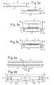
- FIG. 4a shows a schematic side view
- FIG. 4b shows a schematic top view of part of a particularly advantageous embodiment of the ironing machine.
- the lower plate 2 has a slot 16 through which the pants 13 are inserted so that the waistband in the slot 16 hangs down.
- Two trouser legs 13a and 13b are each stretched in the transverse direction by moving the sheets 14 and 15 apart and then smoothed in the longitudinal direction by moving the pairs of sheets 14, 15 between the elastically stretchable covers 3, 4. This procedure is common in double leg ironing machines and results in pants lying largely flat on the lower plate.
- a light barrier 17 it may be necessary for a light barrier 17 to indicate the presence of the trousers 13. The further tensioning and ironing processes take place in the manner described above.
- the clamping bars 5,6,7,8 are not only vertical but can also be moved horizontally to the ironing surface. Also in this embodiment can thus obtain a desired tensile effect on the ironing material 13 However, there is a larger installation space for the movement of the clamping bars 5,6,7,8 required.
- control of the drive devices 9, 10, 11, 12, i.e. the control and the coordination of the pneumatic or hydraulic cylinders or the electric motors, is carried out by means of suitable control circuits, as they are commonly used.
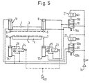
- FIG. 5 schematically shows an example of a circuit for a pneumatic system for driving the tensioning device.
- a printing unit 18 supplies the entire system with constant air pressure.
- Via two 5/2-way valves 19, 20 can each drive devices 9, 10, 11, 12 Clamping bars 5,6,7,8 can be controlled.
- the 5/2-way valves are 19.20 each actuated by a solenoid valve 21, 22, the solenoid valves 21,22 electrically switched into a blocking and a passage position can be operated, whereby the 5/2-way valves 19, 20 against spring force will.
- the upper chambers of cylinders 9 and 10 are via the 5/2-way valves 19 and 20 each vented.
- solenoid valves 23 and 24 are over the light barrier 17 operated, as will be explained later. They are parallel to the check valves 25,26 switched.
- the drive devices 9 and 12 are supplied with compressed air and the pistons pressed down accordingly.
- the compressed air supply to the upper one Chamber of the drive device 12 takes place via the check valve 25, because the solenoid valve 23 is already based on the signal from the light barrier 17 was closed.
- the stretchable covers 3 and 4 are over the Draw the edge of the lower plate 2 and tension it - as already described several times - The intermediate pants 13, so that the Upper plate 1 can iron the pants 13.
- the top plate 1 is raised again and also the solenoid valve 21 returns to its original position, so that the 5/2-way valve 19 comes into position 19a by means of spring force.
- the Solenoid valve 23 is still kept closed, which leads to the fact that only the upper chamber in the cylinder of the drive device 9, but not in the cylinder of the drive device 12 is vented.
- the upper chamber in the cylinder of the drive device 12 can not be vented because on the one hand the solenoid valve 23 is closed and on the other hand the check valve 25 blocks in venting direction. As a result, only that rises upper front spar 5 and detaches from the pants 13, while the lower front clamping bar 7 remains in the cocked position.
Landscapes
- Engineering & Computer Science (AREA)
- Textile Engineering (AREA)
- Treatment Of Fiber Materials (AREA)
- Treatment And Processing Of Natural Fur Or Leather (AREA)
- Irons (AREA)
Description
- Spannen von jedem Hosenumschlag mittels des Spannsystems durch Auseinanderbewegen der beiden Bleche jedes Blechpaars in Querrichtung;
- Längsspannen der Hosenbeine durch Auseinanderbewegen der Blechpaare in Längsrichtung; und
- Schließen der Bügelflächen durch Aufeinanderbewegen von Ober- und Unterform und Anwenden von Wärme, Druck und/oder Feuchtigkeit, ist dadurch gekennzeichnet, daß vor dem Schließen der Bügelflächen ein einseitiger Zug auf das Bügelgut ausgeübt wird durch:
- Bewegen der beiden Spannholme der einen Seite von Ober- und Unterform auf eine Niveau unterhalb der Unterform oder oberhalb der Oberform; und
- Halten der beiden Spannholme auf der anderen Seite von Ober- und Unterform auf Höhe der Unterform.
- nach dem Bügeln des Bügelguts die Oberform angehoben wird;
- der obere dehnbare Bezug mit den oberen Spannholmen vom Bügelgut abgehoben und entspannt wird; während
- der untere dehnbare Bezug mit den unteren Spannholmen gespannt gehalten wird, bis die Lichtschranke anzeigt, daß das Bügelgut aus der Bügelmaschine herausgenommen wurde, wodurch die Magnetventile in Durchlaßstellung geschaltet und die unteren Spannholme nach oben bewegt werden.
- Fig. 1
- eine schematische Perspektivdarstellung einer Bügelmaschine gemäß der Erfindung;
- Fig. 2a bis c
- schematische Seitenansichten von verschiedenen Spannmöglichkeiten bei der erfindungsgemäßen Bügelmaschine;
- Fig. 3a bis c
- Verfahrensschritte beim Bügeln mit der erfindungsgemäßen Bügelmaschine in schematischen Seitenansichten;
- Fig. 4a und 4b
- eine Seit- und eine Draufsicht von einer anderenAusführungsform der erfindungsgemäßen Bügelmaschine mit einem Spannsystem zum Spannen von Hosenumschlägen; und
- Fig. 5
- eine schematische Darstellung einer Pneumatikschaltung für die erfindungsgemäße Bügelmaschine.
Fig. 4a zeigt eine schematische Seitansicht und Fig. 4b eine schematische Draufsicht auf einen Teil einer besonders vorteilhaften Ausführungsform der Bügelmaschine. Es ist zu erkennen, daß die Unterplatte 2 einen Schlitz 16 aufweist, durch den die Hose 13 eingeführt wird, so daß der Hosenbund im Schlitz 16 nach unten hängt. Zwei Hosenbeine 13a und 13b werden jeweils durch Auseinanderbewegen der Bleche 14 und 15 in Querrichtung gespannt und anschließend durch Auseinanderbewegen der Blechpaare 14,15 zwischen den elastisch dehnbaren Bezügen 3,4 in Längsrichtung glattgezogen. Dieses Verfahren ist bei Doppelbeinbügelmaschinen üblich und führt zu einer weitgehend flachliegenden Hose auf der Unterplatte. Für die Steuerelektronik kann es notwendig sein, daß eine Lichtschranke 17 das Vorhandensein der Hose 13 anzeigt. Die weiteren Spann- und Bügelvorgänge erfolgen in der oben beschriebenen Weise.
Claims (14)
- Bügelmaschine mit je einer oder mehreren Ober- und Unterformen (1,2), die gegeneinander preßbar angeordnet sind und an ihren einander zugekehrten Seiten eine Bügelfläche aufweisen, wobei mindestens einer, vorzugsweise jeder der Ober- und Unterformen (1,2) mindestens zwei senkrecht zur Bügelfläche bewegbare Spannholme (5,6,7,8) mit einem dazwischen angebrachten, elastisch dehnbaren Bezug (3,4) zugeordnet sind, dadurch gekennzeichnet, daß jedem Spannholm (5,6,7,8) jeweils eine eigene Antriebseinrichtung (9,10,11,12) derart zugeordnet ist, daß jeder Spannholm unabhängig von dem oder den anderen Spannholm(en) (5,6,7,8) im wesentlichen senkrecht zur Bügelfläche bewegbar ist.
- Bügelmaschine nach Anspruch 1, dadurch gekennzeichnet, daß eine Ober- (1) und eine Unterform (2) vorhanden sind, denen jeweils ein zwischen jeweils zwei Spannholmen (5,6,7,8) vorhandener, elastisch dehnbarer Bezug (3,4) zugeordnet ist, wobei die beiden Spannholme (5,7) auf einer Seite von Ober- und Unterform (1,2) mittels ihrer jeweiligen Antriebseinrichtung (9,12) unabhängig von den beiden Spannholmen (6,8) auf der anderen Seite von Ober- und Unterform (1,2) bewegbar sind.
- Bügelmaschine nach Anspruch 1 oder 2, dadurch gekennzeichnet, daß die Spannholme (5,6,7,8) parallel zueinander angeordnet sind und vorzugsweise auch parallel zu den zugeordneten Kanten der Bügelfläche liegen.
- Bügelmaschine nach einem der Ansprüche 1 bis 3, dadurch gekennzeichnet, daß die Antriebseinrichtung (9,10,11,12) hydraulische, pneumatische oder elektrische Stellglieder aufweist.
- Bügelmaschine nach einem der Ansprüche 1 bis 4, dadurch gekennzeichnet, daß die Bügelmaschine durch eine Steuerelektronik steuerbar ist.
- Bügelmaschine nach einem der Ansprüche 1 bis 5, dadurch gekennzeichnet, daß der elastisch dehnbare Bezug (3,4) ein Stretchcord ist.
- Bügelmaschine nach einem der vorstehenden Ansprüche, dadurch gekennzeichnet, daß ein Spannsystem (14,15) zum Spannen von Hosenumschlägen vorhanden ist.
- Bügelmaschine nach Anspruch 7, dadurch gekennzeichnet, daß das Spannsystem zwischen Ober- und Unterform (1,2) zwei aus jeweils zwei Blechen (14,15) bestehende Blechpaare aufweist, wobei jeweils ein Blechpaar durch Auseinanderbewegen der beiden Bleche (14,15) in einer Querrichtung einen Hosenumschlag spannt, und die beiden Blechpaare in einer Längsrichtung voneinander wegbewegbar sind.
- Bügelmaschine nach einem der vorstehenden Ansprüche, dadurch gekennzeichnet, daß die Antriebseinrichtungen (9,10,11,12) pneumatische Kolben-Zylinder-Einheiten sind und daß eine Steuerschaltung (19,20,21,22) vorhanden ist zum Verbinden der Kolben-Zylinder-Einheiten mit einer Druckluftzufuhr (18) oder Entlüftungsöffnungen.
- Bügelmaschine nach Anspruch 9, dadurch gekennzeichnet, daß die Kolben-Zylinder-Einheiten der zu den unteren Spannholmen (7,8) gehörenden Antriebseinrichtungen (11,12) über eine Ventilanordnung (23,25; 24,26) mit der Druckluftzufuhr (18) oder den Entlüftungsöffnungen verbunden sind.
- Bügelmaschine nach Anspruch 10, dadurch gekennzeichnet, daß die Ventilanordnung für jede der zu den unteren Spannholmen (7,8) gehörenden Antriebseinrichtungen (11,12) jeweils ein Rückschlagventil (25; 26) und ein parallel dazu geschaltetes, von einer das Vorhandensein eines Bügelguts (13) anzeigenden Lichtschranke (17) gesteuertes Magnetventil (23; 24) aufweist.
- Bügelmaschine nach Anspruch 11, dadurch gekennzeichnet, daß die Magnetventile (23,24) in Sperrstellung stehen, wenn die Lichtschranke (17) das Vorhandensein von Bügelgut (13) anzeigt.
- Verfahren zum Pressen von Bügelgut (13), insbesondere Hosen, mit einer Bügelmaschine nach einem der Ansprüche 1 bis 12, mit den Schritten:dadurch gekennzeichnet, daß vor dem Schließen der Bügelflächen ein einseitiger Zug auf das Bügelgut (13) ausgeübt wird durch:Spannen von jedem Hosenumschlag mittels des Spannsystems durch Auseinanderbewegen der beiden Bleche (14,15) jedes Blechpaars in Querrichtung;Längsspannen der Hosenbeine durch Auseinanderbewegen der Blechpaare (14,15) in Längsrichtung; undSchließen der Bügelflächen durch Aufeinanderbewegen von Ober- und Unterform (1,2) und Bügeln des Bügelguts (13) durch Anwenden von Wärme, Druck und/oder Feuchtigkeit,Bewegen der beiden Spannholme (5,7) der einen Seite von Ober- und Unterform (1,2) auf ein Niveau unterhalb der Unterform (2) oder oberhalb der Oberform (1); undHalten der beiden Spannholme (6,8) der anderen Seite von Ober- und Unterform (1,2) auf Höhe der Unterform (2).
- Verfahren nach Anspruch 13 mit einer Bügelmaschine nach einem der Ansprüche 11 oder 12, dadurch gekennzeichnet, daßnach dem Bügeln des Bügelguts (13) die Oberform (1) angehoben wird;der obere dehnbare Bezug (3) mit den oberen Spannholmen (5,6) vom Bügelgut (13) abgehoben und entspannt wird; währendder untere dehnbare Bezug (4) mit den unteren Spannholmen (7,8) gespannt gehalten wird, bis die Lichtschranke (17) anzeigt, daß das Bügelgut (13) aus der Bügelmaschine herausgenommen wurde, wodurch die Magnetventile (23,24) in Durchlaßstellung geschaltet und die unteren Spannholme (7,8) nach oben bewegt werden.
Applications Claiming Priority (3)
| Application Number | Priority Date | Filing Date | Title |
|---|---|---|---|
| DE4409876 | 1994-03-22 | ||
| DE4409876A DE4409876C1 (de) | 1994-03-22 | 1994-03-22 | Bügelmaschine mit Spann- und Streckvorrichtung und Bügelverfahren |
| PCT/EP1995/000645 WO1995025839A1 (de) | 1994-03-22 | 1995-02-22 | Bügelmaschine mit spann- und streckvorrichtung |
Publications (2)
| Publication Number | Publication Date |
|---|---|
| EP0742853A1 EP0742853A1 (de) | 1996-11-20 |
| EP0742853B1 true EP0742853B1 (de) | 1998-04-29 |
Family
ID=6513521
Family Applications (1)
| Application Number | Title | Priority Date | Filing Date |
|---|---|---|---|
| EP95911251A Expired - Lifetime EP0742853B1 (de) | 1994-03-22 | 1995-02-22 | Bügelmaschine mit spann- und streckvorrichtung |
Country Status (6)
| Country | Link |
|---|---|
| EP (1) | EP0742853B1 (de) |
| JP (1) | JPH10500317A (de) |
| CN (1) | CN1144546A (de) |
| DE (2) | DE4409876C1 (de) |
| ES (1) | ES2116079T3 (de) |
| WO (1) | WO1995025839A1 (de) |
Families Citing this family (4)
| Publication number | Priority date | Publication date | Assignee | Title |
|---|---|---|---|---|
| DE29511292U1 (de) * | 1995-07-12 | 1996-11-07 | Brisay Maschinen GmbH, 63741 Aschaffenburg | Bügelmaschine |
| CN107299511B (zh) * | 2017-07-06 | 2023-08-04 | 浙江凌志智能科技有限公司 | 一种绳带烫平机 |
| CN110371746A (zh) * | 2019-07-18 | 2019-10-25 | 上海航星机械(集团)有限公司 | 一种熨平机的涨紧结构 |
| CN112981890B (zh) * | 2021-02-04 | 2022-06-14 | 郑州市娅丽达服饰有限公司 | 一种服装设计衣服熨烫装置 |
Family Cites Families (6)
| Publication number | Priority date | Publication date | Assignee | Title |
|---|---|---|---|---|
| DE1157192B (de) * | 1962-03-27 | 1963-11-14 | Kannegiesser & Co Maschinenfab | Buegelpresse zum Buegeln von mit zwei roehrenfoermigen Fortsaetzen versehenen Bekleidungsstuecken, insbesondere Hosen |
| US3126658A (en) * | 1964-03-26 | 1964-03-31 | carskadon | |
| US3685179A (en) * | 1971-03-30 | 1972-08-22 | Strauss Levi & Co | Garment spreading apparatus |
| US4137655A (en) * | 1976-10-16 | 1979-02-06 | Euro Pressing Group Limited | Apparatus for pressing trousers |
| ATE44057T1 (de) * | 1986-07-18 | 1989-06-15 | Texma Textilmasch & Armaturen | Buegelmaschine. |
| JPH06104157B2 (ja) * | 1990-01-12 | 1994-12-21 | 幸男 宮田 | 刺繍用アイロン仕上げ装置 |
-
1994
- 1994-03-22 DE DE4409876A patent/DE4409876C1/de not_active Expired - Fee Related
-
1995
- 1995-02-22 DE DE59502053T patent/DE59502053D1/de not_active Expired - Fee Related
- 1995-02-22 ES ES95911251T patent/ES2116079T3/es not_active Expired - Lifetime
- 1995-02-22 CN CN95192170A patent/CN1144546A/zh active Pending
- 1995-02-22 JP JP7524322A patent/JPH10500317A/ja active Pending
- 1995-02-22 WO PCT/EP1995/000645 patent/WO1995025839A1/de not_active Ceased
- 1995-02-22 EP EP95911251A patent/EP0742853B1/de not_active Expired - Lifetime
Also Published As
| Publication number | Publication date |
|---|---|
| EP0742853A1 (de) | 1996-11-20 |
| JPH10500317A (ja) | 1998-01-13 |
| CN1144546A (zh) | 1997-03-05 |
| WO1995025839A1 (de) | 1995-09-28 |
| DE59502053D1 (de) | 1998-06-04 |
| DE4409876C1 (de) | 1995-05-18 |
| ES2116079T3 (es) | 1998-07-01 |
Similar Documents
| Publication | Publication Date | Title |
|---|---|---|
| EP0253048B1 (de) | Bügelmaschine | |
| EP0742853B1 (de) | Bügelmaschine mit spann- und streckvorrichtung | |
| DE3119661C2 (de) | Vorrichtung zum Zuführen von Wäschestücken zu einer Mangel | |
| DE3507757C2 (de) | Maschine zum Dämpfen und Glätten von Bekleidungsstücken und Verfahren zum Betrieb einer solchen Maschine | |
| DE3531954C1 (de) | Vorrichtung zum Glaetten von Oberbekleidungsstuecken wie Sakkos,Maentel und dergl. | |
| EP0508211B1 (de) | Vorrichtung zum Halten und Führen von Material an Stickmaschinen | |
| DE19629071C1 (de) | Vorrichtung zum Fangen einer gerissenen Bedruckstoffbahn | |
| DE2847805A1 (de) | Verfahren und vorrichtung zum dampfbuegeln der saumbereiche von rohrfoermigen kleidungsstuecken | |
| DE102020209819A1 (de) | Folienklemmung | |
| DE60127242T2 (de) | Automatische Maschine zum Bügeln von Hosen und Jeans oder elastischen Hosen oder Sporthosen | |
| AT388189B (de) | Buegelmaschine | |
| DE2723596A1 (de) | Buegelvorrichtung | |
| DE1460996A1 (de) | Verfahren und Vorrichtung zum Buegeln von Hosen | |
| DE2646764A1 (de) | Verfahren und vorrichtung zum buegeln von hosen | |
| DE2612322A1 (de) | Presse | |
| DE3228622C2 (de) | Vorrichtung zum Bügeln von Nähten an rohrförmig geschlossenen Bekleidungsstücken, wie Hosenbeinen, Ärmeln o. dgl. | |
| DE1962611C (de) | Bügelpresse mit mehreren Arbeits- und Preßstationen | |
| DE1962611A1 (de) | Buegelmaschine fuer Oberbekleidungsstuecke | |
| DE8713696U1 (de) | Ärmelspannvorrichtung für Bügelmaschinen | |
| DE924024C (de) | Verfahren zur Endbehandlung roehrenfoermiger Teile von Kleidungs-stuecken und Vorrichtung zur Durchfuehrung des Verfahrens | |
| DE2636463A1 (de) | Vorrichtung zum verformen von platten aus thermoplastischem kunststoff | |
| DE219798C (de) | ||
| DE1962611B (de) | Bügelpresse mit mehreren Arbeits- und Preßstationen | |
| DE550052C (de) | Einrichtung an einer Buegelmaschine, um Luft durch das Werkstueck hindurchzutreiben | |
| DE1137413B (de) | Buegelpresse fuer Kleidungsstuecke od. dgl. |
Legal Events
| Date | Code | Title | Description |
|---|---|---|---|
| PUAI | Public reference made under article 153(3) epc to a published international application that has entered the european phase |
Free format text: ORIGINAL CODE: 0009012 |
|
| 17P | Request for examination filed |
Effective date: 19960730 |
|
| AK | Designated contracting states |
Kind code of ref document: A1 Designated state(s): DE ES FR GB IT PT SE |
|
| GRAG | Despatch of communication of intention to grant |
Free format text: ORIGINAL CODE: EPIDOS AGRA |
|
| 17Q | First examination report despatched |
Effective date: 19970610 |
|
| GRAG | Despatch of communication of intention to grant |
Free format text: ORIGINAL CODE: EPIDOS AGRA |
|
| GRAH | Despatch of communication of intention to grant a patent |
Free format text: ORIGINAL CODE: EPIDOS IGRA |
|
| GRAH | Despatch of communication of intention to grant a patent |
Free format text: ORIGINAL CODE: EPIDOS IGRA |
|
| GRAA | (expected) grant |
Free format text: ORIGINAL CODE: 0009210 |
|
| AK | Designated contracting states |
Kind code of ref document: B1 Designated state(s): DE ES FR GB IT PT SE |
|
| REF | Corresponds to: |
Ref document number: 59502053 Country of ref document: DE Date of ref document: 19980604 |
|
| GBT | Gb: translation of ep patent filed (gb section 77(6)(a)/1977) |
Effective date: 19980521 |
|
| REG | Reference to a national code |
Ref country code: ES Ref legal event code: FG2A Ref document number: 2116079 Country of ref document: ES Kind code of ref document: T3 |
|
| ET | Fr: translation filed | ||
| ITF | It: translation for a ep patent filed | ||
| REG | Reference to a national code |
Ref country code: PT Ref legal event code: SC4A Free format text: AVAILABILITY OF NATIONAL TRANSLATION Effective date: 19980430 |
|
| PLBE | No opposition filed within time limit |
Free format text: ORIGINAL CODE: 0009261 |
|
| STAA | Information on the status of an ep patent application or granted ep patent |
Free format text: STATUS: NO OPPOSITION FILED WITHIN TIME LIMIT |
|
| 26N | No opposition filed | ||
| PGFP | Annual fee paid to national office [announced via postgrant information from national office to epo] |
Ref country code: GB Payment date: 20000128 Year of fee payment: 6 |
|
| PGFP | Annual fee paid to national office [announced via postgrant information from national office to epo] |
Ref country code: PT Payment date: 20000131 Year of fee payment: 6 Ref country code: FR Payment date: 20000131 Year of fee payment: 6 |
|
| PGFP | Annual fee paid to national office [announced via postgrant information from national office to epo] |
Ref country code: SE Payment date: 20000203 Year of fee payment: 6 |
|
| PGFP | Annual fee paid to national office [announced via postgrant information from national office to epo] |
Ref country code: ES Payment date: 20000207 Year of fee payment: 6 |
|
| PG25 | Lapsed in a contracting state [announced via postgrant information from national office to epo] |
Ref country code: GB Free format text: LAPSE BECAUSE OF NON-PAYMENT OF DUE FEES Effective date: 20010222 |
|
| PG25 | Lapsed in a contracting state [announced via postgrant information from national office to epo] |
Ref country code: SE Free format text: LAPSE BECAUSE OF NON-PAYMENT OF DUE FEES Effective date: 20010223 Ref country code: ES Free format text: LAPSE BECAUSE OF NON-PAYMENT OF DUE FEES Effective date: 20010223 |
|
| PG25 | Lapsed in a contracting state [announced via postgrant information from national office to epo] |
Ref country code: PT Free format text: LAPSE BECAUSE OF NON-PAYMENT OF DUE FEES Effective date: 20010831 |
|
| EUG | Se: european patent has lapsed |
Ref document number: 95911251.7 |
|
| GBPC | Gb: european patent ceased through non-payment of renewal fee |
Effective date: 20010222 |
|
| PG25 | Lapsed in a contracting state [announced via postgrant information from national office to epo] |
Ref country code: FR Free format text: LAPSE BECAUSE OF NON-PAYMENT OF DUE FEES Effective date: 20011031 |
|
| REG | Reference to a national code |
Ref country code: FR Ref legal event code: ST |
|
| REG | Reference to a national code |
Ref country code: PT Ref legal event code: MM4A Free format text: LAPSE DUE TO NON-PAYMENT OF FEES Effective date: 20010831 |
|
| PGFP | Annual fee paid to national office [announced via postgrant information from national office to epo] |
Ref country code: DE Payment date: 20020430 Year of fee payment: 8 |
|
| REG | Reference to a national code |
Ref country code: ES Ref legal event code: FD2A Effective date: 20021016 |
|
| PG25 | Lapsed in a contracting state [announced via postgrant information from national office to epo] |
Ref country code: DE Free format text: LAPSE BECAUSE OF NON-PAYMENT OF DUE FEES Effective date: 20030902 |
|
| PG25 | Lapsed in a contracting state [announced via postgrant information from national office to epo] |
Ref country code: IT Free format text: LAPSE BECAUSE OF NON-PAYMENT OF DUE FEES;WARNING: LAPSES OF ITALIAN PATENTS WITH EFFECTIVE DATE BEFORE 2007 MAY HAVE OCCURRED AT ANY TIME BEFORE 2007. THE CORRECT EFFECTIVE DATE MAY BE DIFFERENT FROM THE ONE RECORDED. Effective date: 20050222 |