EP0742734B1 - Karussell - Google Patents
Karussell Download PDFInfo
- Publication number
- EP0742734B1 EP0742734B1 EP95908232A EP95908232A EP0742734B1 EP 0742734 B1 EP0742734 B1 EP 0742734B1 EP 95908232 A EP95908232 A EP 95908232A EP 95908232 A EP95908232 A EP 95908232A EP 0742734 B1 EP0742734 B1 EP 0742734B1
- Authority
- EP
- European Patent Office
- Prior art keywords
- carousel according
- rotor
- carousel
- ground
- radial
- Prior art date
- Legal status (The legal status is an assumption and is not a legal conclusion. Google has not performed a legal analysis and makes no representation as to the accuracy of the status listed.)
- Expired - Lifetime
Links
- 230000008878 coupling Effects 0.000 claims description 6
- 238000010168 coupling process Methods 0.000 claims description 6
- 238000005859 coupling reaction Methods 0.000 claims description 6
- 238000007373 indentation Methods 0.000 claims description 3
- 208000027418 Wounds and injury Diseases 0.000 description 7
- 230000006378 damage Effects 0.000 description 7
- 208000014674 injury Diseases 0.000 description 7
- 230000002093 peripheral effect Effects 0.000 description 6
- 229910000831 Steel Inorganic materials 0.000 description 3
- 239000012530 fluid Substances 0.000 description 3
- 239000010959 steel Substances 0.000 description 3
- 239000000969 carrier Substances 0.000 description 2
- 230000002349 favourable effect Effects 0.000 description 2
- 230000004888 barrier function Effects 0.000 description 1
- 238000011109 contamination Methods 0.000 description 1
- 238000005260 corrosion Methods 0.000 description 1
- 230000007797 corrosion Effects 0.000 description 1
- 239000002184 metal Substances 0.000 description 1
- 239000000725 suspension Substances 0.000 description 1
Images




Classifications
-
- A—HUMAN NECESSITIES
- A63—SPORTS; GAMES; AMUSEMENTS
- A63G—MERRY-GO-ROUNDS; SWINGS; ROCKING-HORSES; CHUTES; SWITCHBACKS; SIMILAR DEVICES FOR PUBLIC AMUSEMENT
- A63G1/00—Roundabouts
- A63G1/12—Roundabouts rotated by the passengers themselves
- A63G1/16—Roundabouts rotated by the passengers themselves rotated by means of grip-rings
Definitions
- the invention relates to a carousel for people, in particular for children, with one standing still relative to the ground Substructure which is provided substantially perpendicular to the floor Stator axis and one essentially parallel to the ground provided support star, and one around the stator axis rotatable rotor with a rotating part to take away of people.
- Carousels of this type such as those from the DE-GM 18 06 045 are known, in particular as children's play equipment known from public playgrounds or from the private sector. For one, these carousels must be the most professional as well take care of improper use by small children and provide adequate security. On the other hand, they have to Carousels should be designed so that even when used by young people or adults the higher loads then occurring be included.
- the invention has for its object a carousel to create the type mentioned, that with easy handling and versatility sufficient security with proper and improper use.
- the star in the recesses of the base plate in can be used essentially positively.
- the star therefore no longer poses a risk of injury the supporting star about its form-fitting definition the base plate arranged against rotation, so that on the Substructure acting torque on the edges of the recesses is supported.
- the profiling of the base plate ensures that the on the Transfer the forces acting on the base plate to the surface will.
- the profile is a good anchor for the bottom the bottom plate with the ground, for example the ground.
- the base plate sinks slightly into the ground the base plate is practically form-fitting on the floor fixed.
- the base plate increases the contact area of the substructure on the floor, causing excessive sinking of the substructure in a possibly damp floor prevents.
- the base plate advantageously forms a fluid-tight seal down and protects against contamination of the supporting star.
- the support star which is often made of metal, is therefore against Corrosion influences protected from the underground.
- the carousel is also below through the base plate locked childproof around, so that actually one undesired turning of the carousel no risk of injury consists.
- centering shoulder is provided on the support star, for example, so the central recording is provided on the base plate, and vice versa.
- This alignment of the support star and base plate over the centering heel-central adapter combination ensures that the base plate is always in a precise position with respect to the rotating rotor is arranged.
- a circular base plate can be arranged concentrically to the rotor or stator axis will. This centering is particularly favorable for one exact completion of the base plate with an adjacent rotor part. The parts of the rotor close to the base plate are therefore at Turning the rotor at a radially constant distance from the base plate, so that injuries are prevented.
- the centering shoulder is preferably molded into the base plate Centering pin executed. This allows the centering heel trained together with the profiling of the base plate are.
- the base plate can be made particularly circular and at least on the circumference of an apron of the rotating part to some extent. This creates an overlap area created between the turned part and the base plate, the one molded end between the rotating rotating part and the forms a fixed substructure. Only appears to the outside the apron so that operators between injuries rotating and stationary parts are protected.
- the bottom plate can be circumferentially one have peripheral edge facing the turned part.
- the perimeter can additionally surround the support star and protect it in radial direction outwards.
- Circumferential edge and apron of the turned part together form a kind of labyrinth barrier through which a Access for user, especially children, impossible is.
- the rotor support the rotating part radial support has an angle with the horizontal plane including upward are arranged. Below the horizontal plane is in this context a parallel level to the Floor, and under pointing upwards, the direction away from the floor directed to understand. Due to the angled arrangement of the Radial carriers can do this when there is a load, for example with people occupied, rotor slightly lowered be without the radial support with the base plate or Tragstern collide. The turned part receives through this angled arrangement a certain suspension, which is in comfort for users. Understandably are a substructure for this angled arrangement of the radial supports, a rotor with a rotating part and the radial supports are necessary.
- the angle can advantageously be 1 ° to 5 °.
- the angle can expediently be approximately 2 °.
- the angle is dimensioned such that that the radial beam above the fully loaded rotating part contained their respective starting point on a rotor axis Horizontal plane are arranged. This ensures that the radial struts never fall below a certain one as a result of the load Level decrease so that there is no risk of collision with the Base plate or the support star is made.
- the height of the overlapping corresponds Part of the apron at least the height difference of the radial beams between fully loaded and unloaded rotor.
- the clear distance between the peripheral edge the base plate and the overlapping apron in the loaded and unloaded Condition of the rotor should not exceed three millimeters.
- This small distance is possible between the rotor and the substructure without these two parts turning or turning on one side touch the loaded rotating part.
- the distance of three millimeters is particularly favorable to reach through between the base plate and prevent apron.
- a handwheel is preferably at the upper end of the status axis intended. On the handwheel can be located on the carousel Attack people and turn themselves around with the turned part set the stator axis and the handwheel in rotation.
- the handwheel can be particularly advantageously directed towards the floor have circumferential edge. At this edge, people can attack particularly well with their hands.
- the circumferential edge can advantageously be provided with indentations on the circumference be provided. This makes the handwheel special handy.
- the handwheel can essentially shape a bottle cap.
- this is otherwise ergonomically special shape only suitable for bottle caps cheap and handy.
- the edge is at the bottom of one continuous circular edge completed. Thereby the recesses or the crown cap shape are closed in a circle, so that no injuries when turning around the handwheel can arise.
- the substructure and the rotor can be conceivable via a speed limiting device be connected. This will in particular improper use of the carousel excessive speeds avoided. On the one hand, this means that Limited load protected components protected. On the other hand the speed limiting device can be set so that the maximum speed is just acceptable for small Children is. When mixed with different people Age becomes an acceptable one for the weakest of the passengers None exceed the speed of rotation. For the Speed limitation devices are the substructure and the rotor of the carousel necessary.
- the speed limiting device is a variant of the invention designed as a viscous coupling. Is under viscous coupling in this context to understand a fluid coupling in which a fluid is stirred while rotating the rotor, with the increasing viscosity increases the viscosity of the fluid and the Rotor rotation provides a higher resistance.
- Common Viscous couplings are from the field of automotive engineering known. The viscous coupling has proven to be particularly effective space-saving and inexpensive speed limiting device proved the amazing way in the inventive Carousel is usable.
- the speed limiting device on the handwheel is conceivable be coupled.
- the handwheel is preferably via a limit torque release device connected to the stator axis.
- the limit torque release device creates a non-rotatable until a limit torque is reached Connection between the handwheel and the stator axis.
- the handwheel is opposite the limit torque stationary stator axis rotatable. This ensures that a person rotating with the rotating part turns Gripping the handwheel does not injure it, but it does when the limit torque is exceeded with the person. Thereby injuries are prevented.
- the handwheel can expediently be used by means of an adapter piece be connected to the stator axis.
- the limit torque release device a wedge element that protrudes into the stator axis Adapter piece, at least in some areas, for a friction-locked system expanded on the substructure.
- This is a particularly simple but effective limit torque release device, the limit torque acting between the stator axis and the adapter piece Friction force is determined.
- the limiting torque of the limiting torque releasing device can advantageously be adjustable via an actuator.
- an actuator For example can push the limit torque in or out of the wedge element can be set in the adapter piece.
- the adapter piece can interact with the wedge element Have slots that this adapter piece in divided several tabs.
- the rotor axis be in the upper range via a radial bearing and in the lower area via an axial-radial bearing is stored on the substructure.
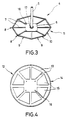
- the substructure 4 has one arranged perpendicular to the floor 1 Stator axis 5, which is perpendicular to a base plate 6 arranged.
- the stator axis is in the center of the surface of the base plate 6 5 is welded with its lower end.
- Of the Base plate 6 extends eight radial struts in a star shape, whose ends 8 lie approximately on a circular path.
- the ends two adjacent radial struts 7 are each one Cross strut 9 connected to each other. All cross struts form together a circumferential polygon 10.
- the base plate 6 with the Radial struts 7 are arranged and form approximately in one plane together a supporting star 11.
- the bottom plate 12 has a circular shape External shape and corresponds to the shape of the Carrying star 11 arranged recesses 13. Circumferential the base plate 12 has a peripheral edge directed away from the base 1 14 on. Elevations are between the depressions 13 15 trained.
- the base plate 6 has a hole in the area of each of its corners 16 to which corresponds to a hole 16 in the base plate 12 is provided. Concentric around the stator axis An axial needle bearing 17 is inserted around the base plate 6.
- the cross struts 9, the radial struts 7 and the base plate 6 are made of individual parts and welded together.
- the cross struts 9 and the radial struts 7 are made of rectangular steel tubing with the cross-sectional dimensions 30 x 20 mm at 2 mm Wall thickness made.
- the stator axis consists of a steel tube with cross-sectional dimensions ⁇ 40 x 7 mm.
- the base plate has the dimensions 400 x 400 x 20 mm.
- the rotor has a rotor tube arranged coaxially to the stator axis 5 18 on.
- the rotor tube 18 consists of a steel tube with dimensions ⁇ 100 x 10 mm.
- the rotor tube 18 is on the Stator axis 5 via two radial bearings 19 and an axial bearing 17 stored.
- the radial bearings 19 are designed as deep groove ball bearings. They are arranged far apart from each other, so that a radial bearing 19 as far away from the floor 1 in upper area of the rotor tube 18 and the other radial bearing 19 arranged near the bottom 1 in the lower region of the rotor tube 18 is.
- the end face of the rotor tube 18 is supported on the axial bearing 17 used in the base plate 6.
- the rotor tube 18 is axially immovable, but coaxial the stator axis 5 rotatably supported.
- the thrust bearing 17 and the lower radial bearing also in a combined Axial-radial bearing can be summarized.
- the stator axis 5 protrudes a little from the rotor tube 18 with its upper end forth.
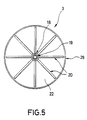
- radial supports are attached to the rotor tube 18 in a star shape 20 welded.
- a circular stiffening plate on the radial supports 20 22 attached.
- the stiffening plate 22 can on the radial supports 20 glued, riveted or screwed to it be. Through the center of the circular stiffening plate 22 enters the rotor tube 18.
- the rotating part 23 On the stiffening plate 22 is the rotating part 23 for Taking people with you.
- the rotating part 23 is formed in two parts and has a base plate 24 with seat support 25 and a seat pan 26 with a backrest 27.
- the footplate 24 extends parallel to the stiffening plate 22 and is with this glued.
- the rotary part 23 has a the circumference Stiffening plate 22 with the radial beams 20 overlapping outside Apron 28 on.
- the seat shell 26 with the Backrest 27 put on.
- the seat shell has an in Circumferential direction of the rotating part 23 circumferential paragraph 29 on the overlaps the seat support 25 on the outside. This is the Seat shell 26 radially immovable to the seat support 25.
- the seat shell 26 is additionally on the seat support 25 glued on.
- the foot plate 24 with seat support 25 and the seat pan 26 with backrest 27 are each as Plastic deep-drawn part.
- seat support 25, seat shell 26 with backrest 27 form together a seat 30 which is circular around the rotor tube 18 and facing it.
- the circular bench 30 is from a sector-shaped entry opening 31 interrupted.
- Side regions 32 of the manhole are the backrest 27 partially continued as a side rest 33.
- a handwheel 34 is arranged at the upper end of the stator axis 5 facing away from the bottom 1 .
- the handwheel 34 is via an adapter piece 35 connected to the end face of the stator axis 5.
- the handwheel 34 extends essentially perpendicular to the Stator axis 5. It is essentially circular and has an edge 36 directed towards the bottom 1.
- the edge 36 has indentations 41 distributed over the circumference, so that the handwheel 34 takes on the overall shape of a crown cap.
- the edge 36 is one continuous circular edge 42 completed.
- the handwheel 34 is designed as a plastic deep-drawn part.
- the apron 28 of the rotating part 23 overlaps the peripheral edge 14 of the base plate 12.
- peripheral edge 14 and apron 28 are spaced from each other by a gap s.
- the gap s when the rotating part is relieved and loaded, i.e. with Turned part 23 occupied by people, maximum 3 mm.
- FIG. 7 shows an exemplary embodiment of a limit torque release device 38 shown.
- This has a wedge element 39, the is arranged within the stator axis 5 and in the lower arranged hollow conical end of the adapter piece 35 is.
- Through the adapter piece 35 extends as Screw 40 trained actuator.
- the screw 40 is screwed in the wedge element 39 and is based on their Head on the slewing ring 34.
- By turning the screw 40 can the wedge element 39 is axially displaced within the stator axis 5 will.
- By moving the wedge element 39 the lower End of the adapter piece 35 expanded accordingly and against pressed the inner wall of the stator axis 5.
- Figure 8 shows the elements for determining the position of the base plate 12 on the substructure 4.
- the base plate 12 has a coaxial to the stator axis 5 arranged centering pin 43, which in the base plate 12 is molded as a projection.
- the centering pin 43 positively engages in a central receptacle 44 bottom end of the stator 5. This is the bottom plate 12 centered on the base 4 in the radial direction.
- the radial support 20 supporting the rotating part 23 is on one Starting point 46 welded to the rotor axis 18. Through the starting point 46 is a horizontal plane running parallel to the floor 1 45 drawn. The radial carrier 20 are opposite the horizontal plane 45 at an angle ⁇ upwards, that is away from the floor. Accordingly, the stiffening plate 25 and the base plate 24 are arranged. The angle ⁇ is 2 °.
- All outward edges of the rotating part 23 are rounded designed with relatively large radius of curvature to prevent injuries to prevent.
Landscapes
- Connection Of Motors, Electrical Generators, Mechanical Devices, And The Like (AREA)
- Transition And Organic Metals Composition Catalysts For Addition Polymerization (AREA)
- Toys (AREA)
- Permanent Magnet Type Synchronous Machine (AREA)
- Arrangement Or Mounting Of Propulsion Units For Vehicles (AREA)
- Handcart (AREA)
- Iron Core Of Rotating Electric Machines (AREA)
Description
- Fig. 1
- einen Vertikalschnitt durch ein erfindungsgemäßes Karussell längs der Schnittlinie I-I in Figur 2,
- Fig. 2
- eine Draufsicht auf ein erfindungsgemäßes Karussell,
- Fig. 3
- eine perspektivische Ansicht eines Standfusses mit senkrecht dazu angeordneter Statorachse,
- Fig. 4
- eine Draufsicht auf eine Bodenplatte mit ausgebildeten Vertiefungen,
- Fig. 5
- eine Unteransicht des Drehteils gemäß der Ansicht der Schnittlinie V-V in Figur 1 mit sternförmig um die Rotorachse angeordneten Radialträgern,
- Fig. 6
- die Einzelheit VI aus Figur 1 in vergrößerter Darstellung,
- Fig. 7
- die Einzelheit VII aus Figur 1 in vergrößerter Darstellung, und
- Fig. 8
- die Einzelheit VIII aus Figur 1 in vergrößerter Darstellung.
Claims (23)
- Karussell für Personen, insbesondere für Kinder, mit einem relativ zum Boden (1) stillstehenden Unterbau (4), der eine im wesentlichen senkrecht zum Boden (1) vorgesehene Statorachse (5) und einen im wesentlichen parallel zum Boden (1) vorgesehenen Tragstern (11) aufweist, und einem um die Statorachse (5) drehbeweglichen Rotor (3) mit einem Drehteil (23) zum Mitnehmen von Personen,
dadurch gekennzeichnet,
daß der Tragstern (11) in im wesentlichen seiner Form entsprechenden Vertiefungen (13) einer profilierten Bodenplatte (12) angeordnet ist, und an Tragstern (11) oder Bodenplatte (12) ein zentraler Zentrierabsatz (43) vorgesehen ist, der in einer am jeweils anderen Teil vorgesehenen Zentralaufnahme (44) eingreifend ausgerichtet ist. - Karussel nach Anspruch 1,
dadurch gekennzeichnet,
daß der Zentrierabsatz als in die Bodenplatte eingeformter Zentrierbolzen (43) ausgeführt ist. - Karussell nach Anspruch 1 oder 2,
dadurch gekennzeichnet,
daß die Bodenplatte (12) kreisrund ausgeführt ist und von einer Schürze (28) des Drehteils (23) umfangsseitig wenigstens ansatzweise übergriffen ist. - Karussell nach einem der vorhergehenden Ansprüche,
dadurch gekennzeichnet,
daß die Bodenplatte (12) umfangsseitig einen zum Drehteil (23) gerichteten Umfangsrand (14) aufweist. - Karussell nach einem der vorhergehenden Ansprüche,
dadurch gekennzeichnet,
daß der Rotor das Drehteil (23) stützende Radialträger (20) aufweist, die einen Winkel (α) mit der Horizontalebene (45) einschließend nach oben gerichtet angeordnet sind. - Karussell nach Anspruch 5,
dadurch gekennzeichnet,
daß der Winkel (α) 1° bis 5° beträgt. - Karussel nach Anspruch 5 oder 6,
dadurch gekennzeichnet,
daß der Winkel (α) ca. 2° beträgt. - Karussell nach einem der Ansprüche 5 bis 7,
dadurch gekennzeichnet,
daß der Winkel (α) derart bemessen ist, daß die Radialträger (20) bei voll belastetem Drehteil (23) oberhalb der ihren jeweiligen Ansatzpunkt (46) an einer Rotorachse (18) enthaltenden Horizontalebene (45) angeordnet sind. - Karussell nach einem der vorhergehenden Ansprüche,
dadurch gekennzeichnet,
daß die Höhe des übergreifenden Teils der Schürze (28) wenigstens der Höhendifferenz der Radialträger (20) zwischen voll belastetem und entlastetem Rotor (3) entspricht. - Karussell nach einem der vorhergehenden Ansprüche,
dadurch gekennzeichnet,
daß der lichte Abstand (s) zwischen dem Umfangsrand (14) der Bodenplatte (12) und der übergreifenden Schürze (28) in be- und entlastetem Zustand des Rotors (3) höchstens 3 mm beträgt. - Karussell nach einem der vorhergehenden Ansprüche,
dadurch gekennzeichnet,
daß am oberen Ende der Statorachse (5) ein Handrad (34) vorgesehen ist. - Karussell nach Anspruch 11,
dadurch gekennzeichnet,
daß das Handrad (34) einen zum Boden (1) gerichteten umlaufenden Rand (36) aufweist. - Karussell nach Anspruch 12,
dadurch gekennzeichnet,
daß der umlaufende Rand (36) umfangsseitig mit Einbuchtungen (41) versehen ist. - Karussell nach einem der Ansprüche 11 bis 13,
dadurch gekennzeichnet,
daß das Handrad (34) im wesentlichen die Form eines Kornkorkens aufweist. - Karussell nach einem der Ansprüche 11 bis 14,
dadurch gekennzeichnet,
daß der Rand (36) bodenseitig von einem durchgehend umlaufenden Kreisrand (42) abgeschlossen ist. - Karussell nach einem der vorhergehenden Ansprüche,
dadurch gekennzeichnet,
daß der Unterbau (4) und der Rotor (3) über eine Drehzahlbegrenzungseinrichtung miteinander verbunden sind. - Karussell nach Anspruch 16,
dadurch gekennzeichnet,
daß die Drehzahlbegrenzungseinrichtung als Visko-Kupplung ausgebildet ist. - Karussell nach einem der Ansprüche 11 bis 17,
dadurch gekennzeichnet,
daß die Drehzahlbegrenzungseinrichtung an das Handrad (34) gekoppelt ist. - Karussell nach einem der Ansprüche 11 bis 18,
dadurch gekennzeichnet,
daß das Handrad (34) über eine Grenzmomentlöseeinrichtung (38) mit der Statorachse (5) verbunden ist. - Karussell nach einem der Ansprüche 11 bis 19,
dadurch gekennzeichnet,
daß das Handrad (34) mittels eines Adapterstücks (35) mit der Statorachse (5) verbunden ist. - Karussell nach einem der Ansprüche 19 oder 20,
dadurch gekennzeichnet,
daß die Grenzmomentlöseeinrichtung (38) ein Keilelement (39) aufweist, das das in die Statorachse (5) hineinragende Adapterstück (35) zumindest bereichsweise zur reibschlüssigen Anlage an dem Unterbau (4) aufweitet. - Karussell nach einem der Ansprüche 19 bis 21,
dadurch gekennzeichnet,
daß das Grenzmoment der Grenzmomentlöseeinrichtung (38) über eine Stellvorrichtung (40) einstellbar ist. - Karussell nach einem der vorhergehenden Ansprüche,
dadurch gekennzeichnet,
daß die Rotorachse (18) im oberen Bereich über ein Radiallager (18) und im unteren Bereich über ein Axial-Radiallager an dem Unterbau (4) gelagert ist.
Applications Claiming Priority (3)
| Application Number | Priority Date | Filing Date | Title |
|---|---|---|---|
| DE4402806 | 1994-01-31 | ||
| DE4402806A DE4402806A1 (de) | 1994-01-31 | 1994-01-31 | Karussell |
| PCT/EP1995/000339 WO1995020426A1 (de) | 1994-01-31 | 1995-01-31 | Karussell |
Publications (2)
| Publication Number | Publication Date |
|---|---|
| EP0742734A1 EP0742734A1 (de) | 1996-11-20 |
| EP0742734B1 true EP0742734B1 (de) | 1998-04-15 |
Family
ID=6509073
Family Applications (1)
| Application Number | Title | Priority Date | Filing Date |
|---|---|---|---|
| EP95908232A Expired - Lifetime EP0742734B1 (de) | 1994-01-31 | 1995-01-31 | Karussell |
Country Status (10)
| Country | Link |
|---|---|
| US (1) | US5795235A (de) |
| EP (1) | EP0742734B1 (de) |
| CN (1) | CN1142195A (de) |
| AT (1) | ATE165020T1 (de) |
| CA (1) | CA2182227A1 (de) |
| DE (2) | DE4402806A1 (de) |
| DK (1) | DK0742734T3 (de) |
| ES (1) | ES2114739T3 (de) |
| GR (1) | GR3026748T3 (de) |
| WO (1) | WO1995020426A1 (de) |
Cited By (1)
| Publication number | Priority date | Publication date | Assignee | Title |
|---|---|---|---|---|
| DE202009007313U1 (de) | 2008-07-14 | 2009-08-13 | Gattinger, Christian, Mag. | Karussell |
Families Citing this family (10)
| Publication number | Priority date | Publication date | Assignee | Title |
|---|---|---|---|---|
| US6319135B1 (en) * | 2000-09-06 | 2001-11-20 | Alan K. Monson | Playground equipment |
| US6808457B1 (en) | 2003-04-28 | 2004-10-26 | Hasbro, Inc. | Sitting toy with water jets |
| US8870668B2 (en) * | 2011-08-17 | 2014-10-28 | Landscape Structures Inc. | Inclusive rotating play device |
| US9033808B1 (en) * | 2013-02-27 | 2015-05-19 | Paul Barenie | Teeter totter apparatus |
| GB201312427D0 (en) * | 2013-07-11 | 2013-08-28 | First Central Developments Ltd | Playground roundabout |
| US9101844B1 (en) | 2013-09-09 | 2015-08-11 | Isabel Perri | Around the world rotary toy system |
| EP3386601A4 (de) * | 2015-12-10 | 2019-10-02 | Landscape Structures Inc. | Rotierende kletternde einheit |
| CA3007757C (en) | 2015-12-10 | 2021-01-19 | Landscape Structures Inc. | Rotating climbing unit |
| US10717012B2 (en) * | 2018-06-15 | 2020-07-21 | Landscape Structures Inc. | Rotating play device |
| US11005339B1 (en) * | 2020-03-06 | 2021-05-11 | Disney Enterprises, Inc. | Spinning amusement park ride with onboard power generation |
Family Cites Families (14)
| Publication number | Priority date | Publication date | Assignee | Title |
|---|---|---|---|---|
| AT4416B (de) * | 1899-12-28 | 1901-06-10 | Gerb Wirth & Co | |
| US1733005A (en) * | 1928-05-09 | 1929-10-22 | Herbert D Clayton | Merry-go-round |
| GB647521A (en) * | 1945-03-26 | 1950-12-13 | Harry Sebel | Improvements in or relating to roundabouts |
| DE910516C (de) * | 1952-04-19 | 1954-05-03 | Frankenthaler Turngeraete U Sc | Kinderkarussell mit von den Sitzen aus von Hand steuerbarem Antrieb durch ein Gestaenge |
| US2686674A (en) * | 1952-06-12 | 1954-08-17 | William F Behrens | Occupant propelled roundabout |
| US2785896A (en) * | 1954-05-24 | 1957-03-19 | Cadwalader H Ellis | Child's merry-go-round |
| DE6600571U (de) * | 1965-06-03 | 1969-01-23 | Mueller W | Zusammenlegbares kleinkarussell |
| DE1806045A1 (de) * | 1968-10-30 | 1970-05-21 | Messerschmitt Boelkow Blohm | Demonstrationswand zum Befestigen von Zeichnungen,Schautafeln od.dgl. |
| DE1941429A1 (de) * | 1969-08-14 | 1971-03-04 | Siebers Gunter | Kleinkarussel fuer Selbstfahrer |
| US3749399A (en) * | 1970-11-02 | 1973-07-31 | R Fedor | Occupant propelled round-about devices |
| DE2255315A1 (de) * | 1972-11-11 | 1974-05-22 | Mars Dame | Drehrollbahn |
| US3873087A (en) * | 1973-04-30 | 1975-03-25 | Gen Mills Fun Group Inc | Occupant propelled rotary amusement device |
| US4119310A (en) * | 1976-03-26 | 1978-10-10 | Patterson-Williams Manufacturing Company | Playground turntable |
| US5118094A (en) * | 1991-02-04 | 1992-06-02 | Today's Kids, Inc. | Rotary amusement device with ratchetable handle |
-
1994
- 1994-01-31 DE DE4402806A patent/DE4402806A1/de not_active Withdrawn
-
1995
- 1995-01-31 WO PCT/EP1995/000339 patent/WO1995020426A1/de not_active Ceased
- 1995-01-31 EP EP95908232A patent/EP0742734B1/de not_active Expired - Lifetime
- 1995-01-31 US US08/682,709 patent/US5795235A/en not_active Expired - Fee Related
- 1995-01-31 DE DE59501916T patent/DE59501916D1/de not_active Expired - Fee Related
- 1995-01-31 DK DK95908232T patent/DK0742734T3/da active
- 1995-01-31 ES ES95908232T patent/ES2114739T3/es not_active Expired - Lifetime
- 1995-01-31 CN CN95191796A patent/CN1142195A/zh active Pending
- 1995-01-31 CA CA002182227A patent/CA2182227A1/en not_active Abandoned
- 1995-01-31 AT AT95908232T patent/ATE165020T1/de not_active IP Right Cessation
-
1998
- 1998-04-28 GR GR980400941T patent/GR3026748T3/el unknown
Cited By (1)
| Publication number | Priority date | Publication date | Assignee | Title |
|---|---|---|---|---|
| DE202009007313U1 (de) | 2008-07-14 | 2009-08-13 | Gattinger, Christian, Mag. | Karussell |
Also Published As
| Publication number | Publication date |
|---|---|
| ES2114739T3 (es) | 1998-06-01 |
| DE4402806A1 (de) | 1995-08-03 |
| CA2182227A1 (en) | 1995-08-03 |
| DE59501916D1 (de) | 1998-05-20 |
| ATE165020T1 (de) | 1998-05-15 |
| EP0742734A1 (de) | 1996-11-20 |
| CN1142195A (zh) | 1997-02-05 |
| DK0742734T3 (da) | 1998-12-07 |
| WO1995020426A1 (de) | 1995-08-03 |
| GR3026748T3 (en) | 1998-07-31 |
| US5795235A (en) | 1998-08-18 |
Similar Documents
| Publication | Publication Date | Title |
|---|---|---|
| DE3531824C2 (de) | ||
| EP0435022B1 (de) | Lenkrolleneinheit | |
| WO1995020426A1 (de) | Karussell | |
| DE69403314T2 (de) | Fussstern für einen Stuhl | |
| DE29921992U1 (de) | Transportrolle mit einem Verriegelungsmechanismus | |
| DE3134179A1 (de) | "stossfeste fussrollenanordung" | |
| DE4305581A1 (de) | Rotor für eine Schwenkbecherzentrifuge | |
| DE2023827A1 (de) | Aufsetzkappe und Druckknopf fur Aerosolbehälter | |
| DE102016015576B3 (de) | Laufvorrichtung für Tiere | |
| DE1429268C3 (de) | Drehstuhl mit einem Standbein | |
| DE1400767C3 (de) | Sicherungsvorrichtung mit federnder, gewölbter Sicherungsscheibe | |
| DE2440789C3 (de) | Drucklager für eine Laufrolle einer Schiebetür | |
| DE1194649B (de) | Kugelbuechse | |
| CH390763A (de) | Glücksspiel | |
| EP2326850B1 (de) | Drehbewegungsdämpfer | |
| DE4111310C2 (de) | Mahlaufsatz für Haushaltsküchenmaschinen | |
| DE2162996A1 (de) | Schachtabdeckung für den Straßen- und Wegebau | |
| DE2035684A1 (de) | Als Fuß fur Möbelstücke oder der gleichen verwendbare Stutze | |
| DE9307699U1 (de) | Hindernisauflage für Springreit-Hindernisstangen | |
| DE69105869T2 (de) | Vorrichtung, die an einem Sessel oder dgl. montiert werden kann. | |
| EP0908116B1 (de) | Tisch mit einer Tischplatte | |
| CH678396A5 (de) | ||
| DE4039475A1 (de) | Lenkrolle | |
| DE8112284U1 (de) | Umlenk-drehscheibe fuer kurvengaengige gliederbandfoerderer | |
| DE8708111U1 (de) | Absperrpoller |
Legal Events
| Date | Code | Title | Description |
|---|---|---|---|
| PUAI | Public reference made under article 153(3) epc to a published international application that has entered the european phase |
Free format text: ORIGINAL CODE: 0009012 |
|
| 17P | Request for examination filed |
Effective date: 19960621 |
|
| AK | Designated contracting states |
Kind code of ref document: A1 Designated state(s): AT BE CH DE DK ES FR GB GR IE IT LI LU MC NL PT SE |
|
| GRAG | Despatch of communication of intention to grant |
Free format text: ORIGINAL CODE: EPIDOS AGRA |
|
| 17Q | First examination report despatched |
Effective date: 19970319 |
|
| GRAG | Despatch of communication of intention to grant |
Free format text: ORIGINAL CODE: EPIDOS AGRA |
|
| GRAH | Despatch of communication of intention to grant a patent |
Free format text: ORIGINAL CODE: EPIDOS IGRA |
|
| GRAH | Despatch of communication of intention to grant a patent |
Free format text: ORIGINAL CODE: EPIDOS IGRA |
|
| GRAA | (expected) grant |
Free format text: ORIGINAL CODE: 0009210 |
|
| AK | Designated contracting states |
Kind code of ref document: B1 Designated state(s): AT BE CH DE DK ES FR GB GR IE IT LI LU MC NL PT SE |
|
| REF | Corresponds to: |
Ref document number: 165020 Country of ref document: AT Date of ref document: 19980515 Kind code of ref document: T |
|
| REG | Reference to a national code |
Ref country code: CH Ref legal event code: NV Representative=s name: ISLER & PEDRAZZINI AG Ref country code: CH Ref legal event code: EP |
|
| GBT | Gb: translation of ep patent filed (gb section 77(6)(a)/1977) |
Effective date: 19980415 |
|
| REF | Corresponds to: |
Ref document number: 59501916 Country of ref document: DE Date of ref document: 19980520 |
|
| REG | Reference to a national code |
Ref country code: ES Ref legal event code: FG2A Ref document number: 2114739 Country of ref document: ES Kind code of ref document: T3 |
|
| ITF | It: translation for a ep patent filed | ||
| REG | Reference to a national code |
Ref country code: IE Ref legal event code: FG4D Free format text: 79877 |
|
| ET | Fr: translation filed | ||
| REG | Reference to a national code |
Ref country code: PT Ref legal event code: SC4A Free format text: AVAILABILITY OF NATIONAL TRANSLATION Effective date: 19980609 |
|
| REG | Reference to a national code |
Ref country code: DK Ref legal event code: T3 |
|
| PLBE | No opposition filed within time limit |
Free format text: ORIGINAL CODE: 0009261 |
|
| STAA | Information on the status of an ep patent application or granted ep patent |
Free format text: STATUS: NO OPPOSITION FILED WITHIN TIME LIMIT |
|
| 26N | No opposition filed | ||
| PGFP | Annual fee paid to national office [announced via postgrant information from national office to epo] |
Ref country code: GR Payment date: 20001229 Year of fee payment: 7 Ref country code: GB Payment date: 20001229 Year of fee payment: 7 |
|
| PGFP | Annual fee paid to national office [announced via postgrant information from national office to epo] |
Ref country code: MC Payment date: 20010102 Year of fee payment: 7 |
|
| PGFP | Annual fee paid to national office [announced via postgrant information from national office to epo] |
Ref country code: PT Payment date: 20010111 Year of fee payment: 7 |
|
| PGFP | Annual fee paid to national office [announced via postgrant information from national office to epo] |
Ref country code: ES Payment date: 20010116 Year of fee payment: 7 |
|
| PGFP | Annual fee paid to national office [announced via postgrant information from national office to epo] |
Ref country code: FR Payment date: 20010118 Year of fee payment: 7 |
|
| PGFP | Annual fee paid to national office [announced via postgrant information from national office to epo] |
Ref country code: AT Payment date: 20010119 Year of fee payment: 7 |
|
| PGFP | Annual fee paid to national office [announced via postgrant information from national office to epo] |
Ref country code: NL Payment date: 20010123 Year of fee payment: 7 Ref country code: LU Payment date: 20010123 Year of fee payment: 7 Ref country code: DK Payment date: 20010123 Year of fee payment: 7 Ref country code: BE Payment date: 20010123 Year of fee payment: 7 |
|
| PGFP | Annual fee paid to national office [announced via postgrant information from national office to epo] |
Ref country code: SE Payment date: 20010124 Year of fee payment: 7 |
|
| PGFP | Annual fee paid to national office [announced via postgrant information from national office to epo] |
Ref country code: IE Payment date: 20010129 Year of fee payment: 7 |
|
| PGFP | Annual fee paid to national office [announced via postgrant information from national office to epo] |
Ref country code: CH Payment date: 20010206 Year of fee payment: 7 |
|
| PGFP | Annual fee paid to national office [announced via postgrant information from national office to epo] |
Ref country code: DE Payment date: 20010228 Year of fee payment: 7 |
|
| REG | Reference to a national code |
Ref country code: GB Ref legal event code: IF02 |
|
| PG25 | Lapsed in a contracting state [announced via postgrant information from national office to epo] |
Ref country code: LU Free format text: LAPSE BECAUSE OF NON-PAYMENT OF DUE FEES Effective date: 20020131 Ref country code: LI Free format text: LAPSE BECAUSE OF NON-PAYMENT OF DUE FEES Effective date: 20020131 Ref country code: IE Free format text: LAPSE BECAUSE OF NON-PAYMENT OF DUE FEES Effective date: 20020131 Ref country code: GB Free format text: LAPSE BECAUSE OF NON-PAYMENT OF DUE FEES Effective date: 20020131 Ref country code: DK Free format text: LAPSE BECAUSE OF NON-PAYMENT OF DUE FEES Effective date: 20020131 Ref country code: CH Free format text: LAPSE BECAUSE OF NON-PAYMENT OF DUE FEES Effective date: 20020131 Ref country code: BE Free format text: LAPSE BECAUSE OF NON-PAYMENT OF DUE FEES Effective date: 20020131 Ref country code: AT Free format text: LAPSE BECAUSE OF NON-PAYMENT OF DUE FEES Effective date: 20020131 |
|
| PG25 | Lapsed in a contracting state [announced via postgrant information from national office to epo] |
Ref country code: SE Free format text: LAPSE BECAUSE OF NON-PAYMENT OF DUE FEES Effective date: 20020201 Ref country code: ES Free format text: LAPSE BECAUSE OF NON-PAYMENT OF DUE FEES Effective date: 20020201 |
|
| BERE | Be: lapsed |
Owner name: KOHL KARIN Effective date: 20020131 Owner name: ULLRICH JURGEN Effective date: 20020131 |
|
| PG25 | Lapsed in a contracting state [announced via postgrant information from national office to epo] |
Ref country code: PT Free format text: LAPSE BECAUSE OF NON-PAYMENT OF DUE FEES Effective date: 20020731 |
|
| PG25 | Lapsed in a contracting state [announced via postgrant information from national office to epo] |
Ref country code: NL Free format text: LAPSE BECAUSE OF NON-PAYMENT OF DUE FEES Effective date: 20020801 Ref country code: MC Free format text: LAPSE BECAUSE OF NON-PAYMENT OF DUE FEES Effective date: 20020801 Ref country code: DE Free format text: LAPSE BECAUSE OF NON-PAYMENT OF DUE FEES Effective date: 20020801 |
|
| PG25 | Lapsed in a contracting state [announced via postgrant information from national office to epo] |
Ref country code: GR Free format text: LAPSE BECAUSE OF NON-PAYMENT OF DUE FEES Effective date: 20020812 |
|
| REG | Reference to a national code |
Ref country code: CH Ref legal event code: PL |
|
| GBPC | Gb: european patent ceased through non-payment of renewal fee |
Effective date: 20020131 |
|
| EUG | Se: european patent has lapsed |
Ref document number: 95908232.2 |
|
| PG25 | Lapsed in a contracting state [announced via postgrant information from national office to epo] |
Ref country code: FR Free format text: LAPSE BECAUSE OF NON-PAYMENT OF DUE FEES Effective date: 20020930 |
|
| NLV4 | Nl: lapsed or anulled due to non-payment of the annual fee |
Effective date: 20020801 |
|
| REG | Reference to a national code |
Ref country code: FR Ref legal event code: ST Ref country code: PT Ref legal event code: MM4A Free format text: LAPSE DUE TO NON-PAYMENT OF FEES Effective date: 20020731 |
|
| REG | Reference to a national code |
Ref country code: IE Ref legal event code: MM4A |
|
| REG | Reference to a national code |
Ref country code: DK Ref legal event code: EBP |
|
| REG | Reference to a national code |
Ref country code: ES Ref legal event code: FD2A Effective date: 20031122 |
|
| PG25 | Lapsed in a contracting state [announced via postgrant information from national office to epo] |
Ref country code: IT Free format text: LAPSE BECAUSE OF NON-PAYMENT OF DUE FEES;WARNING: LAPSES OF ITALIAN PATENTS WITH EFFECTIVE DATE BEFORE 2007 MAY HAVE OCCURRED AT ANY TIME BEFORE 2007. THE CORRECT EFFECTIVE DATE MAY BE DIFFERENT FROM THE ONE RECORDED. Effective date: 20050131 |