EP0740045B1 - Rolladenkasten - Google Patents
Rolladenkasten Download PDFInfo
- Publication number
- EP0740045B1 EP0740045B1 EP96104688A EP96104688A EP0740045B1 EP 0740045 B1 EP0740045 B1 EP 0740045B1 EP 96104688 A EP96104688 A EP 96104688A EP 96104688 A EP96104688 A EP 96104688A EP 0740045 B1 EP0740045 B1 EP 0740045B1
- Authority
- EP
- European Patent Office
- Prior art keywords
- roller blind
- slatted roller
- tool
- blind housing
- flap
- Prior art date
- Legal status (The legal status is an assumption and is not a legal conclusion. Google has not performed a legal analysis and makes no representation as to the accuracy of the status listed.)
- Expired - Lifetime
Links
Images


Classifications
-
- E—FIXED CONSTRUCTIONS
- E06—DOORS, WINDOWS, SHUTTERS, OR ROLLER BLINDS IN GENERAL; LADDERS
- E06B—FIXED OR MOVABLE CLOSURES FOR OPENINGS IN BUILDINGS, VEHICLES, FENCES OR LIKE ENCLOSURES IN GENERAL, e.g. DOORS, WINDOWS, BLINDS, GATES
- E06B9/00—Screening or protective devices for wall or similar openings, with or without operating or securing mechanisms; Closures of similar construction
- E06B9/02—Shutters, movable grilles, or other safety closing devices, e.g. against burglary
- E06B9/08—Roll-type closures
- E06B9/11—Roller shutters
- E06B9/17—Parts or details of roller shutters, e.g. suspension devices, shutter boxes, wicket doors, ventilation openings
- E06B9/17061—Connection of the box to the guides
-
- E—FIXED CONSTRUCTIONS
- E06—DOORS, WINDOWS, SHUTTERS, OR ROLLER BLINDS IN GENERAL; LADDERS
- E06B—FIXED OR MOVABLE CLOSURES FOR OPENINGS IN BUILDINGS, VEHICLES, FENCES OR LIKE ENCLOSURES IN GENERAL, e.g. DOORS, WINDOWS, BLINDS, GATES
- E06B9/00—Screening or protective devices for wall or similar openings, with or without operating or securing mechanisms; Closures of similar construction
- E06B9/02—Shutters, movable grilles, or other safety closing devices, e.g. against burglary
- E06B9/08—Roll-type closures
- E06B9/11—Roller shutters
- E06B9/17—Parts or details of roller shutters, e.g. suspension devices, shutter boxes, wicket doors, ventilation openings
- E06B9/17007—Shutter boxes; Details or component parts thereof
- E06B9/17023—Shutter boxes; Details or component parts thereof made of more than two pieces
Definitions
- the invention relates to a roller shutter box in which a shaft for arranged a developable roller shutter of a window or a door is, and wherein the roller shutter is guided laterally in guide grooves and a flap is provided on the box for revision purposes is.
- roller shutter box is e.g. known from EP-A-0 487 436.
- roller shutter boxes are in the opening area of masonry arranged in the lintel so that the box over the entire lintel width between the longitudinal opening sides of the masonry is introduced.
- the roller shutter is in lateral guide grooves on the window frame or on Masonry are attached, guided.
- the Roller shutter box to the inside of the room a so-called inspection flap on, so that in particular the shaft and also the wound Roller shutters are accessible if any repairs are to be made to them are.
- roller shutter boxes known according to the prior art it is that in particular the roller shutter box that is in the upper Lintel is arranged, can be opened to access in this way to get to the shaft and wind up the roller shutter so far so that it can be easily pushed up into the roller shutter box can push in that in this way a sufficient Opening cross-section is created, through which then into the building can be penetrated.
- the flap a closure device is arranged which opens the box only in the wound state of the roller shutter. Based on these advantageous arrangement of a closure device in the flap, which is only accessible when the roller shutter is rolled up is guaranteed that the roller shutter box is only open for inspection purposes can be, if the roller shutter completely in the roller shutter box on the Shaft is rolled up. This ensures that, in particular closed state a hermetic locking of the roller shutter box is given, as well as in connection with the lowered Closure the shutter unit forms a hermetic lock. This also ensures that the inspection flap is only open can be, for example, the homeowner or owner is in his house and then the roller shutter in the roller shutter box wound up.
- the closure device arranged inside the box and only by means of operated by a tool.
- the fact that the closure device can only be operated using a specially designed tool can, the security of the roller shutter box is increased in that for example, the tools required to open the roller shutter box can be kept under lock and key.
- the locking device consists of a bolt, which is in a guide on the Flap inside is slidably mounted.
- the sliding inside Bolt is designed as a bolt and has one circumferential groove in which the tool designed as a hook shape can be locked to unlock. Is it necessary that for Example for revision purposes the roller shutter box must be opened, so the roller shutter is first wound up in the roller shutter box, so that the end bar up to the opening area of the roller shutter box disappears.
- the tool is set so that the Hook shape protrudes into the box area, the hook then in engages the circumferential groove of the bolt, so that a form connection is produced and the bolt can be moved laterally, so that it is moved to a release position and the flap is swung open can be.
- the bolt is expediently against the pretension a spring slidably mounted in the guide. Now shut up closed again, the bolt is due to the pre-tensioned Spring moved back to the closed position. The free can End of the bolt in the locked state of the flap either the Reach behind the side wall of the front cover or it engages a sleeve integrally formed on the end cover.
- the guide for the Bolt sleeve-shaped and being an area on the guide is provided, which specifies the displacement path for the tool.
- This area of the displacement path is on the guide recessed so that the necessary displacement, which is with the tool is initiated, is provided on the closure device, in order to swing open the flap on the roller shutter box.
- this points Area towards the inside of the box.
- the hook shape of the tool grips the inside Closure device, and wherein a nose is formed on the end of the hook is that in the groove of the bolt, in the area of the displacement is arranged, engages.
- roller shutter box 1 shows the roller shutter box 1 according to the invention, in which a shaft, not shown, for a roller shutter that can be developed a window or a door is arranged. It won't Closure shown in detail laterally in guides that act as guide grooves 2 are formed, guided.
- the roller shutter box 1 will in particular by a ceiling panel 3, a front panel 4 and formed by end plates 5 each arranged on the end faces.
- the Rear wall and the bottom wall of the roller shutter box 1 by one at the Ceiling plate 3 hinged flap 6 formed, in particular for inspection purposes can be swung open to this Way to the inner shaft and not shown to reach the windable roller shutters.
- closure device 7 on the inside of the flap 6 arranged, the opening of the roller shutter box 1 only in the wound Condition of the roller shutter.
- the internal locking device 7 is to be actuated by means of a tool 8, the Tool 8 can only be applied when the roller shutter is complete is wound up in the roller shutter box 1.
- closure device 7 from a bolt 9, which is in a guide 10 on the inside of the flap is molded, is slidably mounted.
- the bolt 9 is designed as a bolt and has a circumferential around its central area Groove 11 into which the tool 8 designed as a hook shape for Unlocking can be latched, as shown in Figures 1 and 2 becomes.
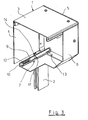
- the partially cut Figure 3 shows that the as a bolt trained latch 9 against the bias of a spring 12 in the Guide 10 is slidably mounted. The spring thus causes the bolt 9 is always pressed against the face plate 5.
- the guide 10 for the bolt 8th formed sleeve-shaped, and has a recessed region 14 on, which is provided for the displacement of the tool 8.
- the recessed area 14 is in particular arranged in such a way that it points inwards, so that only with the tool 8 loosening of the bolt 9 is possible.
- the internal locking device 7 encompasses the hook shape of the tool 8 the internal locking device 7 such that a nose formed on the end of the hook 15 can engage in the groove 11 of the bolt 9.
- the tool can only be applied when the roller shutter is completely in the roller shutter box 1 is wound up, only then is there the possibility to penetrate the roller shutter box 1 with the hook-shaped tool 8, to attach the hook shape according to Figure 2. Only in this position of the tool 8 can the arranged lever 16 are operated according to the direction of arrow 17 to the latch 9 to move in its leadership 10. In this way the closure device 7 unlocked and the flap 6 can be swung open become.
- overflow slide guides 18 are in the field the lateral locking guides 2, in particular on the locking device 7, overflow slide guides 18 arranged.
- These overflow slide guides 18 allow in particular that of the closure device 7 sliding shutters not on the locking device 7 hooks or jams. This ensures that the roller shutter always slides over the locking device 7 can be.
Landscapes
- Engineering & Computer Science (AREA)
- Structural Engineering (AREA)
- Architecture (AREA)
- Civil Engineering (AREA)
- Operating, Guiding And Securing Of Roll- Type Closing Members (AREA)
- Window Of Vehicle (AREA)
- Feeding, Discharge, Calcimining, Fusing, And Gas-Generation Devices (AREA)
- Storage Of Harvested Produce (AREA)
- Rolls And Other Rotary Bodies (AREA)
- Footwear And Its Accessory, Manufacturing Method And Apparatuses (AREA)
Description
- Fig. 01:
- Eine teilweise perspektivische Darstellung des erfindungsgemäßen Rolladenkastens, wobei die vordere Kastenwand ausgespart ist;
- Fig. 02:
- Eine weitere perspektivische Darstellung gemäß der Figur 1, wobei die Blickrichtung von der Innenseite her auf die erfindungsgemäße Verschlußvorrichtung gerichtet ist;
- Fig. 03:
- Eine weitere perspektivische Darstellung der Erfindung gemäß der Figur 1 und 2, wobei die Verschlußvorrichtung teilweise in der Schnittdarstellung dargestellt ist.
Claims (10)
- Rolladenkasten, in dem eine Welle für einen abwickelbaren Rolladen eines Fensters oder einer Tür angeordnet ist und wobei der Rolladen seitlich in Führungsnuten geführt ist und an dem Rolladenkasten für Revisionszwecke eine Klappe vorgesehen ist, dadurch gekennzeichnet, daß an der Klappe (6) eine Verschlußvorrichtung (7) angeordnet ist, die ein Öffnen des Rolladenkastens (1) nur im aufgewickelten Zustand des Rolladen zuläßt.
- Rolladenkasten nach Anspruch 1, dadurch gekennzeichnet, daß die Verschlußvorrichtung (7) innenliegend im Rolladenkasten (1) angeordnet ist und nur mittels eines Werkzeugs (8) betätigbar ist.
- Rolladenkasten nach den Ansprüchen 1 oder 2, dadurch gekennzeichnet, daß die Verschlußvorrichtung (7) aus einem Riegel (9) besteht, der in einer Führung (10) an der Klappeninnenseite verschiebbar gelagert ist.
- Rolladenkasten nach Anspruch 2 und 3, dadurch gekennzeichnet, daß der Riegel (9) als Bolzen ausgebildet ist und eine umlaufende Nut (11) aufweist, in die das als Hakenform ausgebildete Werkzeug (8) zum Entriegeln einrastbar ist.
- Rolladenkasten nach Anspruch 4, dadurch gekennzeichnet, daß der Riegel (9) gegen die Vorspannung einer Feder (12) in der Führung (10) verschiebbar gelagert ist.
- Rolladenkasten nach Anspruch 5, dadurch gekennzeichnet, daß das freie Ende des Riegels (9) im verriegelten Zustand der Klappe (6) entweder die Seitenwandung des Stirndeckels (5) hintergreift oder in eine an dem Stirndeckel (5) angeformte Hülse (13).
- Rolladenkasten nach Anspruch 3, dadurch gekennzeichnet, daß die Führung (10) für den Riegel (9) hülsenförmig ausgebildet ist, und ein Bereich (14) für den Verschiebeweg des Werkzeugs (8) ausgespart ist.
- Rolladenkasten nach Anspruch 7, dadurch gekennzeichnet, daß der Bereich (14) zum Kasteninneren weist.
- Rolladenkasten nach den Ansprüchen 1 bis 8, dadurch gekennzeichnet, daß im Bereich der seitlichen Verschlußführungen (2) auf der Verschlußvorrichtung (7) Überlaufgleitführungen (18) angeordnet sind.
- Rolladenkasten nach einem oder mehreren der vorhergehenden Ansprüche, dadurch gekennzeichnet, daß die Hakenform des Werkzeugs (8) die innenliegende Verschlußvorrichtung (7) umgreift, und wobei endseitig eine Nase (15) angeformt ist, die in die Nut (11) des Riegels (9), die im Bereich (14) des Verschiebeweges angeordnet ist, eingreift.
Applications Claiming Priority (2)
| Application Number | Priority Date | Filing Date | Title |
|---|---|---|---|
| DE29506815U DE29506815U1 (de) | 1995-04-28 | 1995-04-28 | Rolladenkasten |
| DE29506815U | 1995-04-28 |
Publications (3)
| Publication Number | Publication Date |
|---|---|
| EP0740045A2 EP0740045A2 (de) | 1996-10-30 |
| EP0740045A3 EP0740045A3 (de) | 1998-04-08 |
| EP0740045B1 true EP0740045B1 (de) | 1999-05-12 |
Family
ID=8007171
Family Applications (1)
| Application Number | Title | Priority Date | Filing Date |
|---|---|---|---|
| EP96104688A Expired - Lifetime EP0740045B1 (de) | 1995-04-28 | 1996-03-25 | Rolladenkasten |
Country Status (5)
| Country | Link |
|---|---|
| EP (1) | EP0740045B1 (de) |
| AT (1) | ATE180041T1 (de) |
| DE (2) | DE29506815U1 (de) |
| ES (1) | ES2132796T3 (de) |
| PL (1) | PL181164B1 (de) |
Families Citing this family (8)
| Publication number | Priority date | Publication date | Assignee | Title |
|---|---|---|---|---|
| GR960100283A (el) * | 1996-08-08 | 1998-04-30 | ������ ��� ��� �.�. | Κουτι ρολου θυρων και παραθυρων. |
| CZ9005U1 (cs) * | 1999-04-22 | 1999-08-27 | Isotra S.R.O. | Nosný profil pro uložení pohonného mechanismu proovládání žaluzií |
| DE19959736C2 (de) * | 1999-12-10 | 2001-06-07 | Dyna Fenster & Tueren Gmbh | Rolladen-Aufsatzkasten |
| FR2835876B1 (fr) * | 2002-02-13 | 2004-09-24 | Bubendorff Volet Roulant | Dispositif de fixation d'une sous-face sur un caisson tunnel de volet roulant |
| FR2873399B1 (fr) * | 2004-07-20 | 2006-09-22 | Bubendorff Sa | Dispositif de trappe de visite pour caisson de tablier de volet roulant |
| FR2883323B1 (fr) | 2005-03-21 | 2007-05-11 | Bubendorff Sa | Dispositif de verrouillage d'une sous-face de caisson de volet roulant formant trappe de visite |
| FR3068065B1 (fr) * | 2017-06-22 | 2019-07-19 | Bubendorff Sa | Trappe de visite pour installation de volet roulant. |
| PL435318A1 (pl) | 2020-09-15 | 2022-03-21 | Stec Kazimierz Z.P.U.H. Promyk | Obudowa rolety okiennej |
Family Cites Families (3)
| Publication number | Priority date | Publication date | Assignee | Title |
|---|---|---|---|---|
| DE8311752U1 (de) * | 1983-04-20 | 1983-10-13 | Bohnert, Reinhard, 7570 Baden-Baden | Vorrichtung zur festlegung und zum verschluss des deckels eines rolladenkastens |
| DE3628238A1 (de) * | 1986-08-20 | 1988-03-10 | Bohn Edith | Rolladenkasten |
| FR2669372B1 (fr) * | 1990-11-20 | 1993-01-29 | Bubendorff Richard | Caisson de volet roulant. |
-
1995
- 1995-04-28 DE DE29506815U patent/DE29506815U1/de not_active Expired - Lifetime
-
1996
- 1996-03-25 ES ES96104688T patent/ES2132796T3/es not_active Expired - Lifetime
- 1996-03-25 DE DE59601853T patent/DE59601853D1/de not_active Expired - Fee Related
- 1996-03-25 EP EP96104688A patent/EP0740045B1/de not_active Expired - Lifetime
- 1996-03-25 AT AT96104688T patent/ATE180041T1/de not_active IP Right Cessation
- 1996-04-22 PL PL96313888A patent/PL181164B1/pl unknown
Also Published As
| Publication number | Publication date |
|---|---|
| ES2132796T3 (es) | 1999-08-16 |
| DE29506815U1 (de) | 1996-05-23 |
| PL313888A1 (en) | 1996-11-12 |
| DE59601853D1 (de) | 1999-06-17 |
| EP0740045A2 (de) | 1996-10-30 |
| ATE180041T1 (de) | 1999-05-15 |
| EP0740045A3 (de) | 1998-04-08 |
| PL181164B1 (pl) | 2001-06-29 |
Similar Documents
| Publication | Publication Date | Title |
|---|---|---|
| EP0040800B1 (de) | Rolladen | |
| EP1705335A2 (de) | Rolladenkastenabdeckung | |
| EP1538298B1 (de) | Schiebefenster, Schiebetür oder dergleichen mit wenigstens einem steuerbaren Dichtungselement zwischen einem Flügel und einer festen Einfassung | |
| EP1885977B1 (de) | Sicherheits-verschlussvorrichtung für eine tür, ein tor oder dergleichen | |
| DE102018121307B4 (de) | Flugzeugtürverriegelung, Flugzeugtür und Flugzeug mit einer Flugzeugtür | |
| DE3135401A1 (de) | Tor mit einer verriegelungseinrichtung | |
| EP0740045B1 (de) | Rolladenkasten | |
| DE202022100517U1 (de) | Profilanordnung eines Fensters oder einer Tür mit einem Flügelprofil, insbesondere einem Schiebeflügelprofil | |
| DE19507852C1 (de) | Türverschluß mit mehreren Schließstangen | |
| EP3658734B1 (de) | Torsystem | |
| DE10015095C2 (de) | Verriegelungsvorrichtung für einen Türflügel | |
| DE102014111131A1 (de) | Vorrichtung zur Ver- und Entriegelung eines Fensterflügels, einer Lüftungsklappe oder dergleichen an einem Blendrahmen | |
| DE102017206017B4 (de) | Gebäudeverschlusselement | |
| DE2527880A1 (de) | Vorrichtung zur sicherung von rollaeden | |
| WO2008064890A1 (de) | Vorrichtung zum abdecken einer ausnehmung, insbesondere an einem bauwerk | |
| DE10122526B4 (de) | Karusselltür mit Nachtabschluss | |
| CH687267A5 (de) | Verriegelung fuer Rolltore. | |
| DE102006030675A1 (de) | Sektionaltor | |
| EP0671522A1 (de) | Dachfenster | |
| DE202022103173U1 (de) | Zusatzverriegelungseinrichtung für eine Gebäudeverschlusseinrichtung sowie entsprechende Gebäudeverschlusseinrichtung | |
| EP1813754A2 (de) | Obertürschliesser | |
| EP0693613B1 (de) | Sonnenschutzvorrichtung mit Schnurschloss | |
| DE102022114161A1 (de) | Zusatzverriegelungseinrichtung für eine Gebäudeverschlusseinrichtung, Verfahren zum Montieren einer solchen Zusatzverriegelungseinrichtung sowie entsprechende Gebäudeverschlusseinrichtung | |
| DE202022104654U1 (de) | Profilanordnung eines Fensters oder einer Tür mit einem Flügelprofil, insbesondere einem Schiebeflügelprofil | |
| DE102021115490A1 (de) | Feststellvorrichtung für beidseitig angeschlagene Tür |
Legal Events
| Date | Code | Title | Description |
|---|---|---|---|
| PUAI | Public reference made under article 153(3) epc to a published international application that has entered the european phase |
Free format text: ORIGINAL CODE: 0009012 |
|
| AK | Designated contracting states |
Kind code of ref document: A2 Designated state(s): AT BE DE ES FR IT NL |
|
| PUAL | Search report despatched |
Free format text: ORIGINAL CODE: 0009013 |
|
| AK | Designated contracting states |
Kind code of ref document: A3 Designated state(s): AT BE DE ES FR IT NL |
|
| 17P | Request for examination filed |
Effective date: 19980528 |
|
| GRAG | Despatch of communication of intention to grant |
Free format text: ORIGINAL CODE: EPIDOS AGRA |
|
| 17Q | First examination report despatched |
Effective date: 19980917 |
|
| GRAG | Despatch of communication of intention to grant |
Free format text: ORIGINAL CODE: EPIDOS AGRA |
|
| GRAH | Despatch of communication of intention to grant a patent |
Free format text: ORIGINAL CODE: EPIDOS IGRA |
|
| GRAH | Despatch of communication of intention to grant a patent |
Free format text: ORIGINAL CODE: EPIDOS IGRA |
|
| GRAA | (expected) grant |
Free format text: ORIGINAL CODE: 0009210 |
|
| AK | Designated contracting states |
Kind code of ref document: B1 Designated state(s): AT BE DE ES FR IT NL |
|
| REF | Corresponds to: |
Ref document number: 180041 Country of ref document: AT Date of ref document: 19990515 Kind code of ref document: T |
|
| REF | Corresponds to: |
Ref document number: 59601853 Country of ref document: DE Date of ref document: 19990617 |
|
| ITF | It: translation for a ep patent filed |
Owner name: STUDIO JAUMANN P. & C. S.N.C. |
|
| REG | Reference to a national code |
Ref country code: ES Ref legal event code: FG2A Ref document number: 2132796 Country of ref document: ES Kind code of ref document: T3 |
|
| ET | Fr: translation filed | ||
| PLBE | No opposition filed within time limit |
Free format text: ORIGINAL CODE: 0009261 |
|
| STAA | Information on the status of an ep patent application or granted ep patent |
Free format text: STATUS: NO OPPOSITION FILED WITHIN TIME LIMIT |
|
| 26N | No opposition filed | ||
| PGFP | Annual fee paid to national office [announced via postgrant information from national office to epo] |
Ref country code: DE Payment date: 20040126 Year of fee payment: 9 |
|
| PGFP | Annual fee paid to national office [announced via postgrant information from national office to epo] |
Ref country code: NL Payment date: 20040130 Year of fee payment: 9 Ref country code: FR Payment date: 20040130 Year of fee payment: 9 |
|
| PGFP | Annual fee paid to national office [announced via postgrant information from national office to epo] |
Ref country code: ES Payment date: 20040303 Year of fee payment: 9 |
|
| PGFP | Annual fee paid to national office [announced via postgrant information from national office to epo] |
Ref country code: AT Payment date: 20040325 Year of fee payment: 9 |
|
| PGFP | Annual fee paid to national office [announced via postgrant information from national office to epo] |
Ref country code: BE Payment date: 20040430 Year of fee payment: 9 |
|
| PG25 | Lapsed in a contracting state [announced via postgrant information from national office to epo] |
Ref country code: IT Free format text: LAPSE BECAUSE OF NON-PAYMENT OF DUE FEES;WARNING: LAPSES OF ITALIAN PATENTS WITH EFFECTIVE DATE BEFORE 2007 MAY HAVE OCCURRED AT ANY TIME BEFORE 2007. THE CORRECT EFFECTIVE DATE MAY BE DIFFERENT FROM THE ONE RECORDED. Effective date: 20050325 Ref country code: AT Free format text: LAPSE BECAUSE OF NON-PAYMENT OF DUE FEES Effective date: 20050325 |
|
| PG25 | Lapsed in a contracting state [announced via postgrant information from national office to epo] |
Ref country code: ES Free format text: LAPSE BECAUSE OF NON-PAYMENT OF DUE FEES Effective date: 20050326 |
|
| PG25 | Lapsed in a contracting state [announced via postgrant information from national office to epo] |
Ref country code: BE Free format text: LAPSE BECAUSE OF NON-PAYMENT OF DUE FEES Effective date: 20050331 |
|
| BERE | Be: lapsed |
Owner name: *HENKENJOHANN JOHANN Effective date: 20050331 |
|
| PG25 | Lapsed in a contracting state [announced via postgrant information from national office to epo] |
Ref country code: NL Free format text: LAPSE BECAUSE OF NON-PAYMENT OF DUE FEES Effective date: 20051001 Ref country code: DE Free format text: LAPSE BECAUSE OF NON-PAYMENT OF DUE FEES Effective date: 20051001 |
|
| PG25 | Lapsed in a contracting state [announced via postgrant information from national office to epo] |
Ref country code: FR Free format text: LAPSE BECAUSE OF NON-PAYMENT OF DUE FEES Effective date: 20051130 |
|
| NLV4 | Nl: lapsed or anulled due to non-payment of the annual fee |
Effective date: 20051001 |
|
| REG | Reference to a national code |
Ref country code: FR Ref legal event code: ST Effective date: 20051130 |
|
| REG | Reference to a national code |
Ref country code: ES Ref legal event code: FD2A Effective date: 20050326 |
|
| BERE | Be: lapsed |
Owner name: *HENKENJOHANN JOHANN Effective date: 20050331 |