EP0739720A2 - Dispositif de réglage pour un cylindre de blanchet - Google Patents
Dispositif de réglage pour un cylindre de blanchet Download PDFInfo
- Publication number
- EP0739720A2 EP0739720A2 EP96104600A EP96104600A EP0739720A2 EP 0739720 A2 EP0739720 A2 EP 0739720A2 EP 96104600 A EP96104600 A EP 96104600A EP 96104600 A EP96104600 A EP 96104600A EP 0739720 A2 EP0739720 A2 EP 0739720A2
- Authority
- EP
- European Patent Office
- Prior art keywords
- axis
- rotation
- inner ring
- blanket cylinder
- outer ring
- Prior art date
- Legal status (The legal status is an assumption and is not a legal conclusion. Google has not performed a legal analysis and makes no representation as to the accuracy of the status listed.)
- Granted
Links
- 230000007246 mechanism Effects 0.000 claims abstract description 3
- 230000008878 coupling Effects 0.000 claims description 27
- 238000010168 coupling process Methods 0.000 claims description 27
- 238000005859 coupling reaction Methods 0.000 claims description 27
- 238000007639 printing Methods 0.000 claims description 27
- 230000007704 transition Effects 0.000 claims description 9
- 238000006073 displacement reaction Methods 0.000 claims description 6
- 239000000463 material Substances 0.000 claims description 5
- 230000009471 action Effects 0.000 claims description 3
- 238000007645 offset printing Methods 0.000 claims description 3
- 230000005540 biological transmission Effects 0.000 description 8
- 239000000758 substrate Substances 0.000 description 8
- 230000000694 effects Effects 0.000 description 3
- 230000008859 change Effects 0.000 description 2
- 210000003746 feather Anatomy 0.000 description 2
- 239000013641 positive control Substances 0.000 description 2
- 230000004308 accommodation Effects 0.000 description 1
- 230000006978 adaptation Effects 0.000 description 1
Images


Classifications
-
- B—PERFORMING OPERATIONS; TRANSPORTING
- B41—PRINTING; LINING MACHINES; TYPEWRITERS; STAMPS
- B41F—PRINTING MACHINES OR PRESSES
- B41F13/00—Common details of rotary presses or machines
- B41F13/08—Cylinders
- B41F13/24—Cylinder-tripping devices; Cylinder-impression adjustments
- B41F13/26—Arrangement of cylinder bearings
- B41F13/28—Bearings mounted eccentrically of the cylinder axis
Definitions
- the invention relates to an actuating device for a blanket cylinder, which rolls operationally on a plate cylinder and on a printing substrate supported by an impression cylinder of a printing unit of an offset printing press, the plate cylinder, the blanket cylinder and the impression cylinder each having axes of rotation which span imaginary planes that form a thought prism enclose with a cross section in the form of a triangle with an apex of an obtuse angle located on the axis of rotation of the blanket cylinder, and wherein the axes of rotation of the plate cylinder and the impression cylinder are arranged in a fixed manner with respect to the printing unit, with one in a respective side wall of the printing unit for rotatably receiving the blanket cylinder provided bearing arrangement, each comprising a pair of bearing rings, which rotates in the form of an inner ring bearing the blanket cylinder with an inner ring axis and one of the inner ring in the side wall bar-bearing outer ring with an outer ring axis rotatably mounted in one
- an adjusting device for a pair of blanket cylinders which is part of a printing unit of a web-fed offset printing press.
- a respective blanket cylinder supports the printing substrate against the effect of the other blanket cylinder.
- the blanket cylinders and a respective plate cylinder cooperating therewith are arranged in such a way that their axes of rotation lie approximately in an imaginary plane oblique to the direction of flow of the printing material.
- a respective bearing journal of the blanket cylinder is rotatably received in an eccentric inner ring of a bearing arrangement in which the inner ring is in turn rotatably mounted in an eccentric outer ring which is rotatably mounted in the printing unit.
- Gear means are articulated to a respective inner ring and a respective outer ring, by means of which a rotation of a respective inner ring and a respective outer ring can be carried out in such a way that the axes of rotation of the two blanket cylinders cover said imaginary planes perpendicular to the imaginary plane during said rotation and, depending on the To move the direction of said rotation away from each other or towards each other.
- the aim of this adjusting device is to arrange the blanket cylinders - for example for the purpose of covering them with new blankets - in such a way that they can be separated from one another without moving another printing unit cylinder.
- the invention has for its object to design an actuator of the type mentioned so that an adjustment of the printing gap on the substrate thickness has no effect on the pressure between the blanket cylinder and the plate cylinder.
- a generic actuator is designed such that the second arm of the two-stroke has a length which is several times greater than that of the first arm of the two-stroke, that the second arm of the two-stroke in the starting position of the inner ring, in its end position and in intermediate transition positions orientations with a first main direction essentially radial with respect to the axis of rotation of the plate cylinder, that the first arm of the two-stroke in the starting position of the outer ring, in its end position and in intermediate transition positions orientations with a main direction substantially perpendicular to the first main direction has that the axis of rotation of the blanket cylinder during the rotation of the inner ring and the outer ring from their starting position in their end position with increasing distance from the plane spanned by the axes of rotation of the plate cylinder and the impression cylinder level e passes through a first
- the end of the first travel path section facing away from the second travel path section corresponds to an adjustment of the printing gap to a minimum printing material thickness
- the end of the first travel path section facing the second travel path section corresponds to a position of the blanket cylinder in a first stage “pressure down”.
- the end facing away from the first travel section the second travel path section finally corresponds to a position of the rubber blanket cylinder in a second stage "pressure down", in which the rubber blanket cylinder is turned off both by the impression cylinder and by the plate cylinder.
- the adjustment of the printing gap to increasingly larger printing material thicknesses takes place with the adjusting device according to the invention by adjusting the axis of rotation of the blanket cylinder to locations along the first adjustment path section with an increasingly greater distance of these locations from the end of the first adjustment path section facing away from the second adjustment path section.
- the adaptation of the printing gap to the substrate thickness in this way has no effect on a pressure set between the blanket cylinder and the plate cylinder, as the blanket cylinder moves at least to a large extent on an arc concentric to the plate cylinder when the axis of rotation of which is adjusted along the first travel path section.
- the travel path preferably has an inflection point at which the second travel path section adjoins the first travel path section. This ensures, in particular, that the blanket cylinder is quickly released from the plate cylinder during a transition from the first stage "pressure down” to the second stage "pressure down".
- the actuating device has an adjustable stop, which stops a displacement of the axis of rotation of the rubber blanket cylinder in the direction from the second to the first actuating path section at a selectable location on the first actuating path section.
- the rubber blanket cylinder always reaches the same location on the first travel path section, that is to say always the same, by a corresponding adjustment of the axis of rotation from the positions "pressure down” to a position "pressure on” Attack given setting to a certain substrate thickness.
- the adjusting device has adjusting means, by means of which a first bearing ring of the pair of bearing rings can be rotated relative to the second bearing ring while largely maintaining an instantaneous rotational position of a second bearing ring of the pair of bearing rings.
- the first bearing ring selected is the one which, as a result of the change in its rotational positions while driving through the first travel section, counteracts the tendency of the other bearing ring to move away from the circular axis of the first travel section due to its simultaneous rotation, so that with a with the aid of the adjustment means changing the rotational position of the first bearing ring selected in this way is accompanied by a change in the pressure between the blanket cylinder and the plate cylinder.
- the gear means form a coupling gear in a first variant of the actuating device and a cam gear in a second variant.
- one embodiment of the first variant is distinguished by a composition of the gear means from a drive rocker which can be pivoted by means of the adjusting means and which is mounted by means of a fixed bearing with a pivot axis parallel to the axis of rotation of the blanket cylinder, one on the one hand on the inner ring and on the other hand in a first articulation point the drive linkage articulated first coupling, and a second coupling articulated on the one hand to the outer ring and on the other hand in a second articulation point on the driving linkage.
- Another embodiment of the first variant is characterized by a composition of the gear means a crank arm pivotable by means of the adjusting means, which is mounted by means of a fixed crank bearing with a crank axis parallel to the axis of rotation of the blanket cylinder, one on the one hand to a first bearing ring of the pair of bearing rings and on the other hand to the crank arm articulated coupling rod, and on the one hand to a second bearing ring of the Pair of bearing rings and on the other hand articulated to the coupling rod, the coupling rod on the one hand and the handlebar on the other hand have directions of action which enclose an angle deviating from 90 °.
- a preferred embodiment of gear means in the form of a cam mechanism is characterized by a first cam follower articulated on the inner ring and a second cam follower articulated on the outer ring and by a control cam arrangement interacting with the cam followers with a first cam track controlling the first cam follower and a second cam controlling the second cam follower Curve path, the control cam arrangement being adjustable by means of the adjusting means.
- a control disk carrying the two cam tracks is also preferably provided.
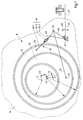
- an eccentric outer ring 12 is mounted rotatably about an outer ring axis 13 in a respective side wall 14 of the printing unit.
- the eccentricity 21 of this outer ring 12 is determined by the distance between the outer ring axis 13 and an inner ring axis 11, with respect to which an eccentric inner ring 10 mounted in the outer ring 12 is rotatable, which together with the outer ring 12 forms a bearing arrangement 8 from a pair of bearing rings.
- the eccentricity 20 of the inner ring 10 is determined by the distance between the inner ring axis 11 and the axis of rotation 7 of a rubber blanket cylinder 1, which is indicated in FIGS. 3 and 4, with respect to which the rubber blanket cylinder 1 mounted in the inner ring 10 is rotatable.
- Corresponding bearing points can be designed as plain bearings or as roller bearings.
- FIGS. 3 and 4 show the position of the blanket cylinder 1 with respect to an associated plate cylinder 2 and an associated impression cylinder 3.
- the blanket cylinder 1, the plate cylinder 2 and the impression cylinder 3 each have axes of rotation 7, 4, 5, which span imaginary planes 6.1, 6.2, 6.3, which form a prism with a cross section in the form of a triangle with one on the axis of rotation 7 of the blanket cylinder 1 include the apex of an obtuse angle.
- the blanket cylinder 1 rolls operationally on the plate cylinder 2 and on a printing substrate 100 supported by the impression cylinder 3 and is placed in a respective starting position of the inner ring 10 and the outer ring 12 under a predetermined pressure on the plate cylinder 2 and on the impression cylinder 3.
- the axis of rotation 7 of the rubber blanket cylinder 1 is located at a first end 28 of the actuating path 15 shown in FIG. 2 facing the plane 6.3, while in a respective end position of the inner ring 10 and the outer ring 12 it faces away from a plane 6.3 second end 29 of the travel path 15 is located.
- the travel path 15 has a first travel path section 26 facing the level 6.3 and an adjoining second travel path section 27 facing away from the level 6.3.
- the first travel section 26 follows an arc of a circle 16 concentric to the plate cylinder 2 at least to a large extent, while the second travel section 27 increasingly moves away from the plate cylinder 2 as the distance from the first travel section 26 increases.
- the adjusting device shown in FIG. 1 is an embodiment of the first variant of the transmission means.
- a drive rocker 40 is pivotally mounted about a fixed bearing 41 with a pivot axis parallel to the axis of rotation 7 of the blanket cylinder 1, and a lever 42, which is firmly connected to the drive rocker 40 and serves as actuating means for actuating the gear means, which moves in the double arrow 45 around the following directions Axis of the bearing 41 is pivotable.
- the gear means further comprise a first coupling 22 articulated on the one hand to the inner ring 10 and in a first articulation point 44 on the drive rocker 40, and a second coupler 24 articulated on the one hand on the outer ring 12 and on the other hand in a second articulation point 43 on the drive rocker 40
- Gear means are thus coupled on the one hand with the inner ring 10 and the outer ring 12 of a respective bearing arrangement 8 and on the other hand with adjusting means.
- the first travel path section 26 which at least to a large extent describes an arc of a circle 16 concentric with the plate cylinder, is by three in particular successive locations on such a circle are approximated and the parameters of the adjusting device are determined for a respective one of these locations.
- the size of the eccentricities 20 and 21 and the mutual rotational position of the inner ring 10 and outer ring 12 are selected so that the displacement of the axis of rotation 7 of the blanket cylinder 1 from the first end 28 of the travel path 15 to the second end 29 of the same with constant rotation of the inner ring and of the outer ring 12 takes place.
- the respective outer ring 12 rotatable about the outer ring axis 13, rotatably mounted in a respective side wall 14 and its eccentricity 21, and with the respective inner ring 10 rotatable in the outer ring 12 about the inner ring axis 11 and rotatably supporting the blanket cylinder 1 and its eccentricity 20
- Kinematically obtained a two-stroke Z of which a first arm Z.1 pivotable about the outer ring axis 13 is represented by the first eccentricity 21 provided on the outer ring 12 and a second arm Z.2 pivotable about the inner ring axis 11 is represented by the second eccentricity 20 provided on the inner ring 10 becomes.
- This second arm Z.2 describes with its free end during said simultaneous rotation of the inner ring 10 and the outer ring 12 from their respective starting position in their respective end position the travel path 15.
- the choice of eccentricities 20 and 21 is made such that the second arm Z.2 of the two-stroke Z has a length that is a multiple of that of the first arm Z.1 of the two-stroke Z.
- the eccentricity 20 of the inner ring 10 is thus a multiple of the eccentricity 21 of the outer ring 12.
- An example of this size ratio the eccentricities 20 and 21 and for the mutual rotational position of the inner ring 10 and outer ring 12 is shown in Fig.
- a further dashed line indicates a circle 17 which has been formed around the axis of rotation 5 of the impression cylinder 3 and which intersects the first travel path section 26 at a location thereof, when it is taken in by the axis of rotation 7 of the blanket cylinder 1, the latter under predetermined pressure against the plate cylinder 2, the impression cylinder 3 just touched. - If, on the other hand, the axis of rotation 7 is in the respective starting position of the inner ring 10 and outer ring 12, there is also a predetermined pressure between the blanket cylinder 1 on the one hand and the impression cylinder 3 on the other.
- the choice of the mutual rotational position of the inner ring 10 and outer ring 12 is also made such that the second arm Z.2 of the two-stroke Z in the starting position of the inner ring 10 in its end position and in intermediate transition positions with orientations one with respect to the axis of rotation 4 of the plate cylinder 2 essentially radial first main direction and the first arm Z.1 of the two-stroke Z in the starting position of the outer ring 12, in its end position and in intermediate transition positions has orientations with a second main direction substantially perpendicular to the first main direction .
- These parameters include first the location for placing a fixed linkage of the transmission means - here by means of the bearing 41 for the drive rocker 40 -. This is selected taking into account the structural conditions and space conditions of the printing unit such that effective transmission angles between the couplers 22 and 24 on the one hand and the drive rocker 40 on the other hand, and between the couplers 22 and 24 on the one hand and the bearing arrangement 8 on the other hand, at least no extremely unfavorable values can be expected .
- these parameters also include the coordinates of the locations of the articulation points 23 and 25 and the articulation points 44 and 43. These are determined by calculation, in which the boundary condition, which is expediently but not necessarily specified, is that that on the inner ring 10 and on the outer ring 12 located pivot points 23 and 25 are provided at least in the vicinity of the greatest ring thickness of inner ring 10 and outer ring 12.
- the axis of rotation 7 of the blanket cylinder 1 runs through the actuating path 15 according to the invention, starting from its first end 28 when the actuating means provided in the form of a lever 42 is pivoted counterclockwise.
- the couplers 22 and 24 between the articulation points 23 and 44 and 25 and 43 convert this pivoting into a counterclockwise rotation of the outer ring 12 and an opposite rotation of the inner ring 10.
- an inflection point 30 forms the transition between the first and the second actuation path sections 26 and 27.
- the first actuation path section 26 largely follows the circle 16 drawn around the axis of rotation 4 in FIG. 2 with a broken line of the plate cylinder 2, not shown here, while the second travel path section 27, starting from the turning point 30, moves away from the plate cylinder 2.
- said two-stroke Z is arranged outside the circle 16, and the inner ring axis 11 is located between the outer ring axis 13 and the plane 6.3.
- An arrangement of a corresponding two stroke within this circle 16 is also conceivable.
- a dotted line in FIG. 2 also shows an adjustment path 15 ′ which is radially displaced towards the axis of rotation 4 of the plate cylinder 2.
- an adjustment path 15 ′ which is radially displaced towards the axis of rotation 4 of the plate cylinder 2.
- a stop 47 which is responsible for the reproducibility of a desired position of the blanket cylinder 1 when it is shifted from its positions at "pressure down" into its “pressure on” position is formed, for example, by means of a fixedly supported adjusting screw, which is a counterclockwise pivoting of the adjusting means provided in the form of the lever 42 is limited.
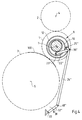
- FIGS. 3 and 4 show particularly advantageous solutions with regard to the accommodation of the gear means in a printing unit.
- a location outside the periphery of the counter-pressure cylinder 3 and approximately at the level of a deepest surface line of the half-speed counter-pressure cylinder 3 is chosen to place a fixed linkage of the gear means, which is otherwise between the plane 6.1 and a plane parallel to it through the axis of rotation 5 of the impression cylinder 3.
- a crank bearing 33 is used with one to the axis of rotation 7 of the Blanket cylinder 1 parallel axis of rotation, with respect to which a crank arm 32 'or 32''can be rotated by means of adjusting means, not shown here.
- the transmission means further comprise a coupling rod 24 'or 24''articulated on the one hand at a pivot point 25' or 25 '' on the outer ring and on the other hand at a pivot point 48 'or 48''on the crank arm 32' or 32 ''. , and on the one hand in a pivot point 23 'or 23''to the inner ring 10 and on the other hand in a pivot point 36' or 36 '' to the coupling rod 24 'or 24''link22' or 22 ''.
- the corresponding parameters of the actuating device are determined in an analogous manner to the exemplary embodiment according to FIG. 1, but with consideration of a further boundary condition, namely that the coupling rod 24 ', 24' 'on the one hand and the link 22', 22 '' on the other hand Have directions of action that enclose an angle deviating from 90 °.
- the adjustment path 15 is traversed from a “pressure on” stage to a “pressure down” stage with the inner ring 10 being rotated clockwise.
- this causes the crank arm 32 ′ to rotate counterclockwise and in the case of the exemplary embodiment according to FIG. 4, the crank arm 32 ′ is rotated clockwise, as with corresponding arrows 34 (in FIG. 3) and 39 (in Fig. 4) is indicated.
- FIGS. 3 and 4 are distinguished from that according to FIG. 1, however, in that only one crank arm 32 ′ or 32 ′′ comparable to the drive element 40 according to FIG. 1 in the area of the bearing arrangement 8 or 8 'reaching gear link in the form of the coupling rod 24' or 24 '' is articulated.
- FIG. 5 enables the course of the first adjustment path section 26 to be approximated to an arc of a circle concentric with the plate cylinder 2, as is shown in FIG. 2 in the form of the circle 16.
- a bearing arrangement 8 ' corresponding to the example according to FIG. 1 with regard to the design and arrangement of the two-stroke Z is provided.
- a first cam follower 49 is on the inner ring 10 and on the outer ring 12 a second cam follower 50 is arranged in the form of a cam roller mounted rotatably with respect to a first and second roller axis 23 '''and25''', respectively, the positions of the roller axes 23 '''and25''' being those the pivot points correspond to 23 and 25 respectively.
- the cam followers 49 and 50 are operatively connected to a control cam arrangement 51 formed by means of a control disk 51.3.
- a first and second cam track 51.1 and 51.2 controlling the first cam follower 49 and a second cam follower 50 controlling the second cam follower 50 are formed on the control disk 51.3, on each of which the Roll cam followers 49 and 50 forming cam rollers when adjusting the cam arrangement 51.
- the adjustment mentioned takes place under a pivoting of the control disk 51.3, which is received for this purpose by means of a bearing 41 with a pivot axis parallel to the roller axes 23 '''or25''.
- the mentioned pivoting takes place by means of an adjusting means in the form of a lever 42 which is firmly connected to the control disk 51.3.
- a respective spring 52 or 53 which acts between the inner ring 10 or the outer ring 12 on the one hand and the printing unit on the other hand maintains a frictional connection between a respective cam roller and the cam track 51.1 or 51.2 interacting therewith.
- An adjustment of the control cam arrangement 51 thus results in a positive control of the inner ring 10 or the outer ring 12.
- Said positive control can be accomplished instead of a positive connection between the cam followers 49 and 50 on the one hand and the control cam arrangement 51 on the other hand by means of a corresponding positive connection.
- a control disk equipped with groove curves is provided.
- the respective course of the groove curves or cam tracks 51.1 or 51.2 used is determined by calculation, while the position of the bearing 41 is determined according to the criteria set out in connection with the exemplary embodiments according to FIGS. 1 to 4.
Applications Claiming Priority (2)
| Application Number | Priority Date | Filing Date | Title |
|---|---|---|---|
| DE19515692 | 1995-04-28 | ||
| DE19515692A DE19515692A1 (de) | 1995-04-28 | 1995-04-28 | Stellvorrichtung für einen Gummituchzylinder |
Publications (3)
| Publication Number | Publication Date |
|---|---|
| EP0739720A2 true EP0739720A2 (fr) | 1996-10-30 |
| EP0739720A3 EP0739720A3 (fr) | 1997-04-16 |
| EP0739720B1 EP0739720B1 (fr) | 1999-11-03 |
Family
ID=7760624
Family Applications (1)
| Application Number | Title | Priority Date | Filing Date |
|---|---|---|---|
| EP96104600A Expired - Lifetime EP0739720B1 (fr) | 1995-04-28 | 1996-03-22 | Dispositif de réglage pour un cylindre de blanchet |
Country Status (7)
| Country | Link |
|---|---|
| US (1) | US5697296A (fr) |
| EP (1) | EP0739720B1 (fr) |
| JP (1) | JP4105248B2 (fr) |
| CN (1) | CN1049624C (fr) |
| AT (1) | ATE186253T1 (fr) |
| CA (1) | CA2172654C (fr) |
| DE (2) | DE19515692A1 (fr) |
Cited By (1)
| Publication number | Priority date | Publication date | Assignee | Title |
|---|---|---|---|---|
| WO2001083214A1 (fr) * | 2000-05-03 | 2001-11-08 | Koenig & Bauer Aktiengesellschaft | Mecanisme permettant d'ajuster l'ecart entre les axes de rotation de cylindres |
Families Citing this family (10)
| Publication number | Priority date | Publication date | Assignee | Title |
|---|---|---|---|---|
| CN1055882C (zh) * | 1997-12-12 | 2000-08-30 | 北京有色金属研究总院 | 一种可焊接不锈钢容器的高温钎料合金粉及其制备方法 |
| CN1055883C (zh) * | 1997-12-22 | 2000-08-30 | 北京有色金属研究总院 | 可焊接不锈钢容器的高熔点低蒸气压钎料合金粉及制法 |
| JP4611493B2 (ja) * | 2000-06-23 | 2011-01-12 | 株式会社小森コーポレーション | 輪転印刷機の胴装置 |
| EP1775125B1 (fr) * | 2001-04-09 | 2009-06-24 | Koenig & Bauer Aktiengesellschaft | Imprimé d'une presse |
| DE10129762B4 (de) * | 2001-06-20 | 2004-07-29 | Koenig & Bauer Ag | Druckeinheit |
| GB2430406A (en) * | 2005-09-21 | 2007-03-28 | Focus Label Machinery Ltd | A printer |
| CN101041285B (zh) * | 2006-03-24 | 2010-04-14 | 海德堡印刷机械股份公司 | 印刷机 |
| DE102007022181B4 (de) * | 2007-05-11 | 2016-04-21 | Koenig & Bauer Ag | Vorrichtung zum Positionieren eines Gummizylinders |
| DE102010030331B4 (de) * | 2010-06-22 | 2013-06-06 | Koenig & Bauer Aktiengesellschaft | Vorrichtungen zur Lagerung eines oder mehrerer Zylinder einer Druckmaschine |
| ES2403133T3 (es) | 2010-11-05 | 2013-05-14 | Neopack, S.L. | Máquina impresora offset de formato variable dotada de un cilindro central de impresión |
Citations (3)
| Publication number | Priority date | Publication date | Assignee | Title |
|---|---|---|---|---|
| DE2718856A1 (de) * | 1976-05-13 | 1978-03-30 | Polygraph Leipzig | Rollenrotations-offsetdruckmaschine fuer schoen- und widerdruck |
| DE3412812C1 (de) * | 1984-04-05 | 1985-06-27 | M.A.N.- Roland Druckmaschinen AG, 6050 Offenbach | Schaltvorrichtung fuer die Gummituchzylinder eines Druckwerkes fuer eine Rollenrotations-Offsetdruckmaschine |
| DE3819159A1 (de) * | 1987-06-22 | 1989-01-05 | Polygraph Leipzig | An- und abstellvorrichtung fuer die gummituchzylinder eines vier-zylinder-druckwerks fuer eine rollenrotations-offsetdruckmaschine |
Family Cites Families (6)
| Publication number | Priority date | Publication date | Assignee | Title |
|---|---|---|---|---|
| DE753695C (de) * | 1940-04-02 | 1952-11-24 | Faber & Schleicher A G | Vorrichtung zum An- und Abstellen des Gummizylinders einer Dreizylinder-Rotationsgummidruckmaschine |
| DE1152704B (de) * | 1962-03-30 | 1963-08-14 | Schnellressenfab Heidelberg | Bogenrotationsmaschine mit Dreizylinderdruckwerk |
| DE1227916B (de) * | 1962-04-28 | 1966-11-03 | Maschf Augsburg Nuernberg Ag | Lageranordnung fuer einen Zylinder von Druckmaschinen, insbesondere fuer den Gummi-zylinder einer Bogenoffsetdruckmaschine |
| GB1181902A (en) * | 1966-03-30 | 1970-02-18 | Adamovske Strojirny Np | Device for Automatically Controlling the Engagement and Disengagement of the Plate Cylinder |
| US3366047A (en) * | 1967-02-23 | 1968-01-30 | Miehle Goss Dexter Inc | Skewing arrangement for plate cylinder and form rollers in printing press |
| DD209776A1 (de) * | 1982-08-24 | 1984-05-23 | Ulrich Hahn | Einrichtung zur einstellung der zylinder in rotationsdruckmaschinen |
-
1995
- 1995-04-28 DE DE19515692A patent/DE19515692A1/de not_active Withdrawn
-
1996
- 1996-03-22 EP EP96104600A patent/EP0739720B1/fr not_active Expired - Lifetime
- 1996-03-22 DE DE59603528T patent/DE59603528D1/de not_active Expired - Lifetime
- 1996-03-22 AT AT96104600T patent/ATE186253T1/de not_active IP Right Cessation
- 1996-03-26 CA CA002172654A patent/CA2172654C/fr not_active Expired - Fee Related
- 1996-04-26 JP JP10721396A patent/JP4105248B2/ja not_active Expired - Fee Related
- 1996-04-29 US US08/639,425 patent/US5697296A/en not_active Expired - Lifetime
- 1996-04-29 CN CN96104921A patent/CN1049624C/zh not_active Expired - Fee Related
Patent Citations (3)
| Publication number | Priority date | Publication date | Assignee | Title |
|---|---|---|---|---|
| DE2718856A1 (de) * | 1976-05-13 | 1978-03-30 | Polygraph Leipzig | Rollenrotations-offsetdruckmaschine fuer schoen- und widerdruck |
| DE3412812C1 (de) * | 1984-04-05 | 1985-06-27 | M.A.N.- Roland Druckmaschinen AG, 6050 Offenbach | Schaltvorrichtung fuer die Gummituchzylinder eines Druckwerkes fuer eine Rollenrotations-Offsetdruckmaschine |
| DE3819159A1 (de) * | 1987-06-22 | 1989-01-05 | Polygraph Leipzig | An- und abstellvorrichtung fuer die gummituchzylinder eines vier-zylinder-druckwerks fuer eine rollenrotations-offsetdruckmaschine |
Cited By (2)
| Publication number | Priority date | Publication date | Assignee | Title |
|---|---|---|---|---|
| WO2001083214A1 (fr) * | 2000-05-03 | 2001-11-08 | Koenig & Bauer Aktiengesellschaft | Mecanisme permettant d'ajuster l'ecart entre les axes de rotation de cylindres |
| US6712001B2 (en) | 2000-05-03 | 2004-03-30 | Koenig & Bauer Aktiengesellschaft | Arrangement for adjusting the interval between the rotational axes of cylinders |
Also Published As
| Publication number | Publication date |
|---|---|
| JP4105248B2 (ja) | 2008-06-25 |
| CN1137448A (zh) | 1996-12-11 |
| ATE186253T1 (de) | 1999-11-15 |
| EP0739720B1 (fr) | 1999-11-03 |
| DE59603528D1 (de) | 1999-12-09 |
| CA2172654C (fr) | 1999-04-20 |
| CA2172654A1 (fr) | 1996-10-29 |
| JPH08300608A (ja) | 1996-11-19 |
| EP0739720A3 (fr) | 1997-04-16 |
| CN1049624C (zh) | 2000-02-23 |
| DE19515692A1 (de) | 1996-10-31 |
| US5697296A (en) | 1997-12-16 |
Similar Documents
| Publication | Publication Date | Title |
|---|---|---|
| DE3417814C2 (fr) | ||
| DE4332364A1 (de) | Druckwerk mit lösbarer Lagerbefestigung | |
| EP0185965B1 (fr) | Cylindre de transfert pour machine à imprimer des feuilles | |
| EP1167028B1 (fr) | Mechanisme d'enlèvement des rouleaux dans une machine d'impression rotative | |
| EP0739720A2 (fr) | Dispositif de réglage pour un cylindre de blanchet | |
| DE19601470B4 (de) | Schleppsaugergetriebe, insbesondere Schleppsaugergetriebe für eine Vorrichtung zur Schrägbogenkorrektur | |
| WO2015120987A1 (fr) | Mécanisme à manivelle multiarticulé d'un moteur à combustion interne ainsi que moteur à combustion interne correspondant | |
| DE2253026C2 (de) | Vorrichtung zum Verschwenken eines Rotorblattes eines Hubschraubers relativ zur Rotornabe | |
| DE10203059B4 (de) | Vorrichtung mit einem ein Greifersystem aufweisenden Zylinder | |
| EP0532934B1 (fr) | Dispositif de commutation de la commande des pinces d'un cylindre à pinces d'un dispositif de retournement dans une machine rotative d'impression recto-verso de feuilles | |
| EP0442265A1 (fr) | Accouplement de serrage pour un composant de réglage déplaçable axialement pour le changement de rotation de la griffe sur une rotative typographique | |
| DE4404752C2 (de) | Vorrichtung zum Verstellen der Falzklappen eines Falzklappenzylinders | |
| DE102007009884B4 (de) | Druckmaschine | |
| DE3833645C2 (fr) | ||
| DE2551949A1 (de) | Steuersystem fuer hydrostatische getriebe | |
| DE4403256A1 (de) | Satellitendruckmaschine | |
| DE19602568C2 (de) | Vorrichtung zum Druckan-/ und -abstellen eines Zylinders | |
| DE2833495A1 (de) | Blattverstellhebel fuer kollektive hubschrauberblattsteuerung | |
| EP0250963A2 (fr) | Dispositif d'entraînement des pinces oscillantes d'une machine à imprimer | |
| DE3922980C2 (fr) | ||
| DE102007011045B4 (de) | Druckmaschine | |
| DE19617625C2 (de) | Offsetdruckpresse | |
| DE10011429A1 (de) | Druckmaschine mit einer Reinigungseinrichtung zur Reinigung zweier Druckmaschinenzylinder | |
| DE3905250C2 (fr) | ||
| EP1818300B1 (fr) | Dispositif de pliage transversal d'un appareil de pliage d'une presse |
Legal Events
| Date | Code | Title | Description |
|---|---|---|---|
| PUAI | Public reference made under article 153(3) epc to a published international application that has entered the european phase |
Free format text: ORIGINAL CODE: 0009012 |
|
| 17P | Request for examination filed |
Effective date: 19960322 |
|
| AK | Designated contracting states |
Kind code of ref document: A2 Designated state(s): AT CH DE FR GB IT LI |
|
| PUAL | Search report despatched |
Free format text: ORIGINAL CODE: 0009013 |
|
| AK | Designated contracting states |
Kind code of ref document: A3 Designated state(s): AT CH DE FR GB IT LI |
|
| GRAG | Despatch of communication of intention to grant |
Free format text: ORIGINAL CODE: EPIDOS AGRA |
|
| GRAG | Despatch of communication of intention to grant |
Free format text: ORIGINAL CODE: EPIDOS AGRA |
|
| 17Q | First examination report despatched |
Effective date: 19981027 |
|
| GRAG | Despatch of communication of intention to grant |
Free format text: ORIGINAL CODE: EPIDOS AGRA |
|
| GRAH | Despatch of communication of intention to grant a patent |
Free format text: ORIGINAL CODE: EPIDOS IGRA |
|
| GRAH | Despatch of communication of intention to grant a patent |
Free format text: ORIGINAL CODE: EPIDOS IGRA |
|
| GRAA | (expected) grant |
Free format text: ORIGINAL CODE: 0009210 |
|
| AK | Designated contracting states |
Kind code of ref document: B1 Designated state(s): AT CH DE FR GB IT LI |
|
| REF | Corresponds to: |
Ref document number: 186253 Country of ref document: AT Date of ref document: 19991115 Kind code of ref document: T |
|
| REG | Reference to a national code |
Ref country code: CH Ref legal event code: EP |
|
| REF | Corresponds to: |
Ref document number: 59603528 Country of ref document: DE Date of ref document: 19991209 |
|
| ITF | It: translation for a ep patent filed |
Owner name: STUDIO JAUMANN P. & C. S.N.C. |
|
| GBT | Gb: translation of ep patent filed (gb section 77(6)(a)/1977) |
Effective date: 20000112 |
|
| ET | Fr: translation filed | ||
| PLBE | No opposition filed within time limit |
Free format text: ORIGINAL CODE: 0009261 |
|
| STAA | Information on the status of an ep patent application or granted ep patent |
Free format text: STATUS: NO OPPOSITION FILED WITHIN TIME LIMIT |
|
| 26N | No opposition filed | ||
| REG | Reference to a national code |
Ref country code: GB Ref legal event code: IF02 |
|
| PGFP | Annual fee paid to national office [announced via postgrant information from national office to epo] |
Ref country code: GB Payment date: 20030224 Year of fee payment: 8 |
|
| PGFP | Annual fee paid to national office [announced via postgrant information from national office to epo] |
Ref country code: FR Payment date: 20030320 Year of fee payment: 8 |
|
| PGFP | Annual fee paid to national office [announced via postgrant information from national office to epo] |
Ref country code: AT Payment date: 20030321 Year of fee payment: 8 |
|
| PGFP | Annual fee paid to national office [announced via postgrant information from national office to epo] |
Ref country code: CH Payment date: 20030403 Year of fee payment: 8 |
|
| PG25 | Lapsed in a contracting state [announced via postgrant information from national office to epo] |
Ref country code: GB Free format text: LAPSE BECAUSE OF NON-PAYMENT OF DUE FEES Effective date: 20040322 Ref country code: AT Free format text: LAPSE BECAUSE OF NON-PAYMENT OF DUE FEES Effective date: 20040322 |
|
| PG25 | Lapsed in a contracting state [announced via postgrant information from national office to epo] |
Ref country code: LI Free format text: LAPSE BECAUSE OF NON-PAYMENT OF DUE FEES Effective date: 20040331 Ref country code: CH Free format text: LAPSE BECAUSE OF NON-PAYMENT OF DUE FEES Effective date: 20040331 |
|
| GBPC | Gb: european patent ceased through non-payment of renewal fee |
Effective date: 20040322 |
|
| REG | Reference to a national code |
Ref country code: CH Ref legal event code: PL |
|
| PG25 | Lapsed in a contracting state [announced via postgrant information from national office to epo] |
Ref country code: FR Free format text: LAPSE BECAUSE OF NON-PAYMENT OF DUE FEES Effective date: 20041130 |
|
| REG | Reference to a national code |
Ref country code: FR Ref legal event code: ST |
|
| PG25 | Lapsed in a contracting state [announced via postgrant information from national office to epo] |
Ref country code: IT Free format text: LAPSE BECAUSE OF NON-PAYMENT OF DUE FEES Effective date: 20050322 |
|
| PGFP | Annual fee paid to national office [announced via postgrant information from national office to epo] |
Ref country code: DE Payment date: 20130424 Year of fee payment: 18 |
|
| REG | Reference to a national code |
Ref country code: DE Ref legal event code: R119 Ref document number: 59603528 Country of ref document: DE |
|
| REG | Reference to a national code |
Ref country code: DE Ref legal event code: R119 Ref document number: 59603528 Country of ref document: DE Effective date: 20141001 |
|
| PG25 | Lapsed in a contracting state [announced via postgrant information from national office to epo] |
Ref country code: DE Free format text: LAPSE BECAUSE OF NON-PAYMENT OF DUE FEES Effective date: 20141001 |