EP0736618B1 - Führungseinrichtung zum Einführen eines Faserbandes in die Klemmlinie von Kalanderscheiben einer faserbandverarbeitenden Textilmaschine und ein Verfahren zum Einführen - Google Patents
Führungseinrichtung zum Einführen eines Faserbandes in die Klemmlinie von Kalanderscheiben einer faserbandverarbeitenden Textilmaschine und ein Verfahren zum Einführen Download PDFInfo
- Publication number
- EP0736618B1 EP0736618B1 EP96102887A EP96102887A EP0736618B1 EP 0736618 B1 EP0736618 B1 EP 0736618B1 EP 96102887 A EP96102887 A EP 96102887A EP 96102887 A EP96102887 A EP 96102887A EP 0736618 B1 EP0736618 B1 EP 0736618B1
- Authority
- EP
- European Patent Office
- Prior art keywords
- sliver
- nozzle
- discs
- calendering
- funnel
- Prior art date
- Legal status (The legal status is an assumption and is not a legal conclusion. Google has not performed a legal analysis and makes no representation as to the accuracy of the status listed.)
- Expired - Lifetime
Links
Images


Classifications
-
- D—TEXTILES; PAPER
- D01—NATURAL OR MAN-MADE THREADS OR FIBRES; SPINNING
- D01H—SPINNING OR TWISTING
- D01H5/00—Drafting machines or arrangements ; Threading of roving into drafting machine
Definitions
- the technical field of the invention is textile machines.
- a section is particularly affected which has a calender device, which usually consists of two opposing calender disks (or a pair of calender rolls) with which the sliver is compacted.
- the invention relates to a guide device with guide nozzles for introducing the sliver between the calender disks and the associated method.
- the invention also affects the wear or replacement parts of the guide device which are subject to greater wear during operation.
- a pair of delivery rollers forms the output of a drafting system of a draw frame (as an example of a sliver processing machine).
- the sliver is spread out according to the roll width.
- the person skilled in the art describes the fiber sliver that is spread out at this point as a non-woven fabric.
- the non-woven fabric ie the spread fiber sliver is conveyed into the opening of a non-woven funnel.
- the nonwoven is collected in the fleece funnel and again formed into a fiber band in the mouth of the fleece funnel.
- the fiber sliver is transported through the funnel mouth of the fleece funnel to a fiber sliver tube which has a considerable length.
- the sliver is introduced into a sliver funnel (also known as a sliver funnel), which deflects the conveying direction of the sliver by approximately 90 ° and introduces it between a pair of calenders (also called a pair of calenders).
- a pair of calenders also called a pair of calenders
- the sliver compacted there is conveyed on to the laying device of the draw frame.
- the sliver tube being designated 8 and the delivery rollers of the draw frame 70b and 70a.
- a structure with a long sliver tube 8 is also described in EP-A 593 884 ; the pair of calender rolls is designated 9a, 9b there.
- Another example of the normality of the long sliver tube is shown in DE-A 26 23 400 .
- the sliver tube itself is curved at an angle of approximately 90 ° and guides the sliver without changing the angle between the calender disks designated 5, 6 there. It is described there as advantageous if the tube denoted by 14 is flattened in an oval shape (compare page 9, last paragraph).
- the DD-A 290 697 also shows a manifold .
- the fleece funnel and belt funnel are clearly at a distance.
- a ventilation opening (there 8) allows the air flowing in at the beginning of a collecting pipe (there 5) to escape completely in front of the narrowest point of the belt funnel.
- DE-A 30 34 812 shows an example of a guide channel (also designated 8 there) which corresponds to the preamble of claim 1.
- Two nozzle sections are nested directly one inside the other in the sliver conveying direction, cf. 1 with the upper long nozzle section 16 there and the lower nozzle section there, which are nested one inside the other in the region of a cylindrical outlet channel (there designated 8), but are firmly fitted into one another and have the guide tube 16 to be designated as longer, which connects the fleece funnel 6 there to the belt funnel and has a flow opening which runs obliquely and laterally into the guide channel.
- a nonwoven fabric can be introduced automatically, which is done by sucking in the compressed air, but only when the end or the lower part of the channel 8 there is open, for which purpose one of the calender disks is brought out of its position by means of a pneumatic cylinder (see page 6, second paragraph).
- a pneumatic cylinder see page 6, second paragraph.
- DE-B 36 12 133 (or FR-A 2,597,119) relates to a belt guide channel between output rollers of the drafting system and downstream belt funnel on a spinning preparation machine.
- the tape guide channel is relatively long and has the large diameter customary in the prior art without changing the cross section.
- the belt guide channel gives the sliver the necessary guidance on the way to the belt funnel. In this way, there are several injectors (air duct, compressed air line) to pull the entire strip mass from the beginning of the strip in the strip guide duct. The entire band mass at the beginning of the band must then be compressed exclusively in the band funnel (column 1, 54th - 58th row there). The problem of air congestion in the belt funnel arises (there column 1, lines 59 to 62).
- the band hopper must have a device for temporarily increasing its cross section. This is a prerequisite for automatic insertion of the sliver.
- the calender disks To automatically insert the beginning of the tape, the calender disks must also be opened, comparable to the forced shutdown of the calender disk in the previously mentioned location. The beginning of the belt cannot be drawn into the clamping gap of the calender discs when the calender discs are closed and when the calender discs are rotating.
- calender rolls or calender disks have been used in the prior art spoken.
- a calender disk has only a smaller width than one Calender roll.
- this has no effect on the function of the following described invention, so that for the sake of simplicity only below one speaks of calender discs or pair of calender discs.
- the invention is based on the task of realizing an automatic transport of the sliver from the fleece funnel to the nip of the calender discs in a compact design and at the same time to simplify the sliver guidance, which also simplifies (accelerated) processing - the introduction of the warped sliver between the calender discs - makes it possible.
- the fleece funnel (as the first nozzle section) and Belt funnel (as a second nozzle section) arranged directly one behind the other, but nested so that they can either be tilted against each other are or both together in relation to another nozzle section in their Angular position are changeable (tiltable) (claim 1). Tilting the axis of the The first nozzle and the second nozzle allow the sliver run to be changed one time through the nozzle insert mentioned and another time not through the nozzle insert, which is the so-called processing position or Preparation is.
- the sliver guide device can be in one part (claim 15) or in several parts (Claim 14) be constructed, wherein it has a smaller insert that than Wear part is interchangeably inserted in the nozzle.
- the wear parts (Claims 16 and 17) are each referred to as indoor use.
- the calender guide nozzle, the pair of calender disks in the area of the nip overlaps (claim 18) forms one side of the pivot bearing for each nozzle sections arranged above or their inner inserts.
- the sliver Due to the immediate nesting, the sliver can omitted and the sliver guide device according to the invention particularly short and compact, at the same time long distances and thus unpleasant dead times in terms of control technology can be reduced (claim 4).
- the sliver guide device according to the invention is of compact design easy to use and even allows two positions nested nozzle sections, once for normal operation and once to work on.
- the compact sliver guiding device can be surprising easy to maintain, easy to adjust and is in its adjustment effort more user-friendly than that in the prior art known, long sliver guides.
- the new design also makes it possible not to introduce it yet stretched fiber fleece to accelerate and simplify and with the calender guide nozzle (Claim 18) to promote behind the nip, sometimes with Air flow (up to the clamping gap), partly with angular momentum of the closed one Calender rolls (through the nip).
- the calender discs apart open clamping gap
- the Beaks of the guide nozzle close to the calender have axially continuous, in radially extending (slight) expansions to (claim 20), the air Guide past the clamping gap.
- the beaks (beak halves) have a length and Width (L, b), which is matched to the expansion (claim 19), that the practically significant part of - or all - of the guide air in the extensions is performed and in the transverse direction (radial direction) without contact in practical is sealed to a significant extent.
- the beaks can be integral with the cone on the fuselage of the nozzle be molded on (claim 21), they need neither to be adjustable in distance be still in alignment with the fuselage part of the band funnel holder.
- the individual nozzle sections of the sliver guide are all close arranged together (claim 4).
- the central axis of each section forms the respective axis of the sliver channel (claim 3), wherein each section is one of can be multiple uses (claim 14).
- Training with several Inserts have the advantage that, despite the compact design, only those elements the entire sliver guide must be replaced, the subject to increased wear. So two interior inserts are provided (claim 16, 17): one of them is an internal insert for the fleece funnel, which shortly after the Delivery rollers of the drafting system is arranged; the other indoor use (claim 17) is the one who forms the band funnel at which the largest Change in diameter of the sliver channel occurs. The interchangeability is also guaranteed when changing lots.
- the essentially loss-free air flow through the two inner inserts through this constitutes a good air balance and low losses with regard to one automated introduction of sliver between the calender discs.
- the provided laterally arranged flow openings in the second Indoor use are advantageously not pivotable and thus fixed positioned.
- the injector is arranged on the belt funnel and the sliver channel above the injector is above the rounded one Articular surface pivotable (claim 5, alternative a).
- the leadership facility has no additional channels for air inflow above the belt funnel.
- the injector can swirl on the guided one Exercise sliver. This is achieved when two injector holes are in parallel offset from the band funnel in a plane of the channel.
- Nozzle section which forms the band funnel
- Nozzle section which forms the band funnel
- the Nozzle section is itself designed to be pivotable and pivot the injector channels arranged in it with (claim 5, alternative b; Claim 9, alternative b; Claim 13).
- Only one guide section remains in the immediate area of the calender discs and the nip (calender guide section) in relation to at least one calender disk unchanged and with respect to this guide section, the rest of the sliver channel extending in the vicinity of the delivery rollers.
- the one mentioned above rounded joint surface is then arranged at the front end of the band funnel and the curved bearing surface on the fixed calender guide section.
- Also here in the operating position there is an airtight coupling in the radial direction achieved so that despite pivotability and modular structure of the Sliver channel (corresponds to a guide channel) a good air balance and low losses can be achieved.
- the low losses in the air budget are also beyond the calender gap retained if the calender guide nozzle is used as a replacement and replacement part its beak section is open on two sides, so that the calender discs partially can engage laterally in the beaks (claim 18).
- the one on the articular surface guided air flow can thus reach the clamping gap and even the clamping gap out past the calender discs so that what is to be inserted Sliver can be guided up to the nip and beyond. Doing so the guide with the two partial round beaks of the calender guide nozzle achieved regardless of whether the calender disks are apart (see above) that there is an open clamping gap) or are assembled (so that the Clamping gap shows almost no passage opening).
- An additional deflecting roller is located at the inlet of the sliver guiding device provided (claim 6), which clearly the guideway of the nonwoven fabric FV changed.
- the significant change is in the direction of the bent nozzle axis Sliver guide device directed so that the first nozzle (the fleece funnel) take up the stretched sliver of the guide device and can merge.
- the angle around the deflection roller is preferably approximately 60 ° the web FV changes the fleece (claim 7).
- the axis of this additional Deflection roller lies in the plane defined by the swivel axis V and the clamping gap becomes.
- the first nozzle has a funnel area (claim 8) and a ramp or plateau area, so that the sliver in the operating position of this nozzle Rolling, deflecting and merging the nonwoven fabric can achieve and at tilted first nozzle of the ramp area ensures that the supplied to him Fleece is deflected so that it is conveyed out of the deflection area
- the drafting system area is not blocked and can be easily removed by the operator.
- the ramp area also ensures that there is no jamming of the nonwoven fabric can form because the first nozzle then by the force of the fleece conveyed on it automatically swiveled and the ramp area up to the still funded fleece derives from the drafting system interior to switch off the delivery rollers.
- the the first nozzle has immediately assumed its processing position, that of the position corresponds to what it assumes when the fleece jams.
- the pivotable first nozzle (claim 8) in the band funnel nozzle can be pivoted (claim 9, Alternative a); the first nozzle can also be used together with one as a band funnel trained directly adjoining nozzle section pivotable on the mentioned calender guide section can be stored (claim 9, alternative b).
- the calender discs remain rotatable without abrasion since they do not touch the mechanical shields used for air guidance. At the same time, however, it is ensured that the space that remains between the areas of the shielding directly adjacent to the sides of the calender disks and the calender disks is as small as possible and practically no air escapes. This air only escapes at the front end of the shields. This location lies behind the (open or closed) clamping gap, viewed in the direction of the sliver transport.
- the fiber fleece is only narrow at the front end brought (to width F1) and the remaining narrower section to one predetermined length, which is the result of the weight of the tape and the length of the Sliver channel from the fleece funnel to the clamping gap results, shortened (to length H).
- Switching on a control for the compressed air supply to generate a short Compressed air pulse causes the narrowed section to be threaded through to Clamping gap, where with the release of a short angular momentum of the calender discs complete threading or complete insertion of the sliver between the calender discs is reached.
- the compressed air pulse can advantageously be coupled with a slight time offset angular momentum of the calender discs, so that the operator alone one Pushing a button is required to thread the sliver.
- a sliver cannot be easier, faster and more reliable, introduced and brought into operating position.
- the sliver is at the front end by the air flow gripped, pulled along the entire sliver channel and directly to the Calender discs submitted.
- the sliver is not "pushed” by compressed air and vented far before the calender discs.
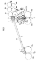
- the overlay in FIG. 1 illustrates the difference from the prior art, which is shown schematically in FIG.
- the sliver FV which has not yet been properly drawn during insertion is introduced into a long guide tube 8 via stretching rollers 68a, 68b, 69a, 69b and delivery rollers 70a, 70b, which ends in a ribbon funnel 9.
- the band funnel 9 deflects the fiber band FB approximately 90 ° into the clamping gap of the calender with its calender discs 100a, 100b.
- the calendered fiber sliver KF emerges vertically downwards from the calender and is stored in a depositing device (not shown).
- This sliver guide is also illustrated in Figure 2 with the same reference numerals.
- An embodiment of the invention shortens the sliver path and leaves that Sliver tube 8 is eliminated.
- An additional deflection roller 71 is added, the one Deflection of about 60 ° causes the fleece conveying direction FV and the sliver in one of several - forming the sliver channel (guide channel) - Introduces functional elements.
- the first element is the fleece funnel 50 (also referred to as a nozzle).
- Fleece funnel represents a nozzle with a substantially rectangular opening
- Fleece funnel has a ramp surface 50b and one arranged directly thereon Funnel section 50a in which the broadly arriving fiber sliver (fiber fleece) rolled up, folded and inserted into a first channel section.
- the Channel section is formed by an insert 40, which is on the rear site of the funnel section 50a of the fleece funnel 50 and with a screw is attached. It can be adjusted.
- the fleece funnel 50 (with inner insert) can be tilted such that the ramp surface 50b in the transport direction of the nonwoven fabric (corresponds Conveying direction) and the funnel section 50a is pivotable next to it.
- an articulated surface 41a, 41b is provided, which in the angular position ⁇ B , which is shown in FIG. 1 or FIG. 2b , enables the guide channel to be sealed off from the subsequent band funnel 30.
- the articulated surface 41a, 41b of the front, cylindrical section of the inner insert 40 which is symmetrical to the central plane of the first insert 40, consists of two continuously curved surface sections 41a, 41b which narrow towards the rear (in the axial direction) and which engage in a corresponding bearing surface 35 on the belt funnel 30.
- 4a and 4b show this joint surface in two views at the front end of the insert 40 for the fleece funnel 50. Swiveling the fleece funnel 50 in the direction ⁇ into the other angular position ⁇ A does not release the radially airtight seal between the fleece funnel and the band funnel. Radially airtight sliver guidance is achieved both in the swung-in ( ⁇ B ) and in the swung-out ( ⁇ A ) state.
- the radial tightness of the joint surface 41a, 41b on the bearing surface 35 is adjustable.
- the upper part (above the articular surface) can do this in the axial direction, especially in the radial direction, can be changed relative to the lower part.
- the basis for the adjustment is the fixed holder 20 in which the Band funnel 30 is used.
- the fleece funnel 50 is designed in two parts - with one against the fleece conveying direction of the sliver inserted into it - insert 40, can on one Handle 51 the aforementioned relative setting are made.
- the fiber sliver is conveyed through the fleece funnel 50, the inner insert 40 and the belt funnel 30 into the guide channel up to the clamping gap 100c, for which purpose the fleece funnel 50 is swung out.
- the fiber fleece part F1 which is narrowed by hand according to FIG. 3 and held in the funnel mouth 50a is sucked in via injector bores 34a, 34b, 64a, 64b on the belt funnel.
- a short suction flow in the time of 500 msec is sufficient to convey the narrowed nonwoven part F1 up to the clamping gap 100c with the least amount of pressure, since the joint surface 35 and the bearing surfaces 41a, 41b of the inner insert 40 are radially airtight. Mechanical insertion aids are not required.
- a short angular momentum of duration T 2 is applied to the calender disks. It can switch itself on after a predetermined suction time T 1 , can be superimposed on it or can be initiated separately manually.
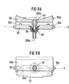
- the shape of the band funnel 30 can be clearly seen in FIGS. 5a, 5b and 5c , where the direction and arrangement of the injector bores 34a, 34b in the band funnel are also shown enlarged. They open into a cylindrical channel 31, which forms the front end of the sliver channel.
- the cylindrical section 31 widens via a conical section 32a to the diameter of the channel 32, which is predetermined by the inner insert 40.
- the bearing surface 35 is provided, which corresponds to the articulation surface 41a, 41b in its curvature.
- the inclined injector bores 34a, 34b can be at an angle of approximately 45 ° run with respect to the axis 200b of the band funnel insert 30. They are advantageously offset in parallel. This will center the sliver possible in the sliver channel. Furthermore, the sliver receives a twist there. The gives the sliver strength.
- the parallel offset injector bores 34a, 34b can be seen in Figure 5d. They open above a cylindrical section 33 of the insert 30 in an outwardly open annular channel 36.
- a band funnel holder 60 according to FIGS. 6a, 6b, 6c has in the upper approximately cylindrical section 67 a central, approximately cylindrical opening 62 into which the band funnel insert 30 is inserted.
- an annular channel 63 which can be fed with compressed air from two or more cylindrical bores 64a, 64b, extends inwardly in the cylindrical opening.
- the compressed air introduced from the outside is introduced into the aforementioned inclined injector bores 34a, 34b when the ribbon funnel insert 30 is inserted, in order to open into the cylindrical section 31 of the fiber ribbon channel, which lies close to the clamping gap 100c.
- FIGS. 6a and 6b illustrate the cylindrical beak 61 of the band funnel holder 60, which adjoins a conical section 68 which forms the transition between the upper cylindrical end 67 and the beak 61. It has a length L and a diameter, shown in the cross section of FIG. 6b as width b.
- the beak 61 is arranged in a fixed manner and has two halves, since - as can be seen in FIG. 6c - it is slit on the side. According to the schematic illustration in FIG. 7 , a segment of the rotating calender disks 100a, 100b engages in the two slots mentioned. This can also be clearly seen in FIG. 1 in the right half. In the middle of the beak of the band funnel holder 60 - i.e.
- clamping gap 100d in the axis 200b of the sliver guide - the clamping gap comes to rest, which according to FIGS. 7a and 7b can both be closed (clamping gap 100c) and also opened by turning off the calender disc 100b can be opened (open clamping gap 100d).
- a first one is used to guide this air narrow channel section 65a on one side of the calender discs or a second narrow channel section 65b on the other side of the calender disks, which have an approximately semicircular cross-sectional shape.
- the respective Channel is very narrow compared to the thickness d or width b of the Schnabels 61 or its inner wall, the immediately the side surface of the Calender disc is adjacent.
- the Beak halves 61a, 61b which have a length L which is approximately half the length Diameter of the calender discs in the embodiment corresponds to the Width b of the beak and overlap d on the inside of the beak half against the calender disc to a sealing effect, which by clear to considerable lateral flow resistance to the axial side air ducts 65a, 65b is formed without contact.
- the air not only passed the calender gap, but also clearly passed through the calender gap.
- the sliver is also immediately threaded through the calender nip and the calender disk 100b can then be delivered in order to have reached the operating position with the sliver threaded.
- the sealing surface part of the cover d
- the sealing surface is large enough in relation to the air resistance of the now enlarged passage channel, consisting of the channel segments 65a, 65b and the open calender gap 100d, in order to prevent radial escape of guide air.
- An example of an air pressure to be used is 4 bar, the is matched to a channel diameter 31 of approximately 3.8 mm in the band funnel 30 and about 8 mm in the channel 45 of the insert 40 of the fleece funnel 50. Try have shown that a compressed air pulse of approx. 500 milliseconds (ms) Duration for the safe insertion of the front part F1 of the nonwoven by Clamping gap 100c is sufficient. The length H1 of the manually narrowed nonwoven is thereby on the distance from the fleece funnel 50 to the clamping gap 100c and thus the The length of the airtight sliver channel is adjusted.
- the mentioned inwardly facing ring channel 63 can be used in an alternative variant also be formed on the insert 30 as an outwardly pointing channel 36, for example by a circumferential notch. Both channels 63, 36 can also be provided in the assembled state of the funnel 30 and holder 60 together to form an annular channel.
- the band funnel holder 60 has between its upper cylindrical portion 62 and its beak section 61 a truncated cone section 68. With him and with the cylindrical portion 68 he can be used in a carrier 20, the Position just above the calender discs 100a, 100b so that the Beak section 61 of the holder 60 over the calender disks and the Clamping gap engages.
- the fleece nozzle 50 is also spaced apart on the carrier 20 creating bearing brackets 52a, 52b pivotally held. All parts of the Nozzle systems are therefore interchangeable, but still fixed exactly in position.
- the possibility of exchanging all parts of the nozzle system opens up the possibility of modular structure of the sliver guiding device, between the exit the delivery rollers and the storage of the calendered sliver. Adjustment work or adjustment work with adjustment to certain calender disc widths or for certain types of fibers or processing specifications are no longer required. If processing specifications are made, there are suitable modules Nozzles that are connected to each other via their respective inserts. The stakes fit into each of the modular nozzles and make the connection between the individual technology parts. The interchangeability also enables one Changeover due to lot change.
- One insert 40 was described with reference to FIGS . 4a, 4b . It is inserted into the fleece funnel 50 against the transport direction of the sliver. Its front end is the hinge surface 41b, 41b, which is attached to a cylindrical tube section 41. It has a continuous curvature which is oriented backwards on both sides of the central plane of the insert 40, the width of which decreases symmetrically on both sides. The width is reduced transversely to the axial direction 200a of the guide channel. The joint surface at the front end has the greatest width.
- the pipe section 41 on which the joint surface 41a, 41b is attached, is arranged in one piece on a cone section 43 which is in a cylindrical Area 45 merges, which has a slightly larger diameter than that also cylindrical insertion section 42.
- the cylindrical section 45 can Exercise as a stop when the insertion section 42 into the fleece funnel 50 from the back (against the direction of transport sliver) is inserted.
- the inner insert 30 for the band funnel holder 60 is shown in FIGS. 5a to 5d . It has the complementary receiving bearing surface 35 to the joint surfaces 41a, 41b of the insert described above. The bearing surfaces 35 also narrow in the direction of the axis 200a of the conveying direction. The bearing surface 35 has the smallest width at the end inlet end of the insert 30.
- the outer dimensions of the insert 30 are designed so that it can be inserted into the band funnel holder 60.
- the holder 60 is formed in one piece and explained in more detail in three views with reference to FIGS. 6a to 6c . It is significantly larger than the actual band funnel, which is formed by the insert 30 in this exemplary embodiment.
- the holder 60 is fixedly fixed in relation to the calender disks, it carries injector nozzles 64a, 64b in order to introduce air in the guide direction into the sliver guide system.
- the air supply is made easier by the fixed attachment of the holder, since it does not have to be pivoted as well.
- Figures 9a, 9b show the fixed holder 20, into which the band funnel holder 60 is inserted into a conical insertion section, so that it is fixed exactly in relation to the calender disks.
- the beak halves 61a, 61b reaching over the calender disks are in the Embodiment each designed semicircular. They are integral to one Cone 68 formed, which is also in one piece in the cylindrical portion 67 of Holder 60 passes over.
- a cylindrical opening 62 is provided in the cylindrical section 67, into which a any band hopper insert 30 can be used.
- the outside dimension each band hopper 30 to be used is on the inside dimension of the holder 60 Voted. Even if there are different technology requirements that the band funnel in a form of the channel 32a, 32, 31, the same can Band funnel holder 60 can be used.
- the flow openings 64a, 64b are provided, with which air is introduced near the calender disks in order to guide them with the half-round beaks 61 in such a way that they at least not in front of the calender gap 100c (or 100d according to FIG. 7b ) can escape.
- widenings 65a, 65b are provided, which lead past the calender gap 100c according to FIG. 7 .
- Their dimension in relation to the width of the calender disks or in relation to the width b of the half-round beaks can be clearly seen from FIG. 7a or 7b .
- FIGS. 8a and 8b show the design of a guide section which is essentially made in one piece and contains both the fleece nozzle 50 and the belt funnel 30.
- the band funnel 30 is inserted directly into the fleece nozzle 50 and is additionally fixed in position by a tube holder 80.
- the front end of the band funnel 30 is supported in comparable bearing shells and rounded surfaces, as described for the fleece funnel insert 40 with reference to FIGS. 4b and 5c .
- FIGS. 8a and 8b The radial seal is also achieved in FIGS. 8a and 8b , where a residual guide section 61 'is fixedly arranged with respect to the calender disks, for example on the holder 20 according to FIG . 9a .
- the remaining guide section 61 ' corresponds to the beak region L of the band funnel holder 60 from FIG . 6a .
- the air is introduced into the combined fleece funnel / belt funnel at the front end thereof via inclined injector bores 34a, 34b, with a pivoting movement causing a slight pivoting of the air introduction region, which, however, is only slight due to its proximity to the pivot point K.
- FIGS. 8a and 8b are designated ⁇ 1 and ⁇ 2 , they correspond to the pivot positions ⁇ A and ⁇ B , but can be dimensioned slightly differently, since the pivotable part in FIGS. 8a and 8b is larger or longer than in Figures 3a and 3b .
- the insert 40 which is both a fleece funnel insert and a belt funnel 30 through different holes and corresponding conical Transition sections defines the sliver guide sections.
- An exchange of the insert 40 is at the same time an exchange of the band funnel 30.
- the annular holder 80 is not quite flush with the combined one Fleece funnel / belt funnel, but leaves an annular space 81 between the Inside of the funnel and the outer diameter of the largely cylindrical Combination funnel 30/40.
- the annular space 81 leads to the fiber guidance Compressed air used, whereby it is at the front end by flush (ring-shaped) Contact on the combination nozzle - below the injector bores 34a, 34b - is sealed.
- At an appropriate height, chosen from the application purpose there is a main air supply leading to the outside Annulus opens, where compressed air can build up and the injector holes 34a, 34b feeds.
- the injector bores are clearly inclined with respect to the axis 200b; they open out directly in front of the radially airtight joint K, on which a radially airtight mounting takes place in both positions of FIG. 8 and FIG. 8b .
- the angles ⁇ 1 and ⁇ 2 are each slightly reduced compared to the example in FIGS. 2a and 2b , but in the same specified range as in FIGS. 2.
- the exact angle in this exemplary embodiment is approximately 5 ° for ⁇ 2 and approximately for ⁇ 1 25 ° ( ⁇ 10%), while in Figure 2a an angle of ⁇ A of approximately 30 ° and in Figure 2b an angle of approximately 7 ° ( ⁇ 10%) worked reliably in the experiment.
- the plateau region 50b in FIGS. 8a and 8b is accordingly somewhat adapted to the angle of the ramp region 50b in FIGS. 2a and 7b. It depends on the angles ⁇ in the respective swivel end positions; where the pivot position ⁇ 1 and ⁇ A specifies such an angle of the ramp that the conveying direction of the nonwoven fabric FV is clearly directed transversely from the exit region of the route. It is most advantageous if the transverse direction FV 'receives a slight component downwards, that is to say is inclined slightly downwards with respect to the horizontal.
- the ramp area either has a slight slope of 1 ° to 2 ° opposite the funnel area or it is slightly conical.
- FIGS. 8a and 8b two different sliver channel dimensions are shown in FIGS. 8a and 8b , a narrow and a wide one, each with a conical shoulder to the narrowest cylindrical section of the sliver channel.
- FIGS Figures 4 and 5 show a side view and a top view of the fleece funnel 50 with its ramp area 50b and its funnel area 50a according to FIG. 3.
- the pivoting axis V is transverse to the guide axis 200a, 200b and runs through the airtight joint 41a, 41b and 35, as in FIGS Figures 4 and 5 explained.
- the pivot axis V runs through the bearings 50c, which are formed by lateral retaining tabs 52a, 52b and pins, on which pivot receptacles that are at least half open on the front can be placed.
- the fleece funnel 50 can thus be removed and tilted, while at the same time sealing the internally formed guide channel 200a, 200b in an airtight manner.
Landscapes
- Engineering & Computer Science (AREA)
- Mechanical Engineering (AREA)
- Textile Engineering (AREA)
- Spinning Or Twisting Of Yarns (AREA)
Description
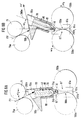
- Figur 1
- ist in Überlagerung eine übliche Gestaltung einer Faserband-Führung mit langem Faserbandrohr und ein Beispiel einer kompakten Bauweise mit ineinandergeschachtelten Düseneinsätzen 30, 40, 50, 60, wovon zwei Düseneinsätze 40, 50 kippbar gegenüber den anderen beiden Düseneinsätzen 30, 60 sind, die an einem fest oberhalb der Kalanderscheiben 100a, 100b angeordneten Düsenhalter 20 angeordnet sind. Die überlagerte Darstellung dient der Veranschaulichung der Verkürzung des Transportweges.
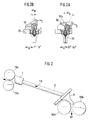
- Figur 2
- verdeutlicht - herausgegriffen aus EP 593 884 - die Faserband-Führung des Standes der Technik mit langem Faserbandrohr 8, Bandtrichter 9 und Kalanderscheiben 100a, 100b. Der Vliestrichter ist mit 1 bezeichnet und die Ausgangswalzen der Strecke mit 70a, 70b.
- Figur 2a
- und
- Figur 2b
- zeigen die zwei Verschwenkstellungen αA , αB der ineinandergeschachtelten Düsen des Gesamt-Düseneinsatzes als Ausführungsbeispiel der Erfindung.
- Figur 3
- zeigt die Vorbereitung des Faservlies F zum Einführen in den Vliestrichter 50.
- Figur 3a
- und
- Figur 3b
- zeigen die beiden Kippstellungen zum Faserbandeinführen und im Betrieb der Strecke.
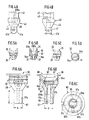
- Figur 4a
- und
- Figur 4b
- zeigen den Inneneinsatz 40 des Vliestrichters 50.
- Figur 5a, Figur 5b, Figur 5c
- und
- Figur 5d
- zeigen den Bandtrichter 30, zum Einsatz in einen Halter 60 gemäß Figur 6a.
- Figur 6a, Figur 6b
- und
- Figur 6c
- zeigen den als Schnabeltrichter gestalteten Halter 60 für den Bandtrichter 30.
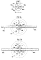
- Figur 7
- zeigt eine schematische Aufsicht auf den Klemmspalt 100c, der vor dem Kalanderscheibenpaar 100a, 100b gebildet wird. Die Luftkanäle 65a, 65b werden außenseitig von den Schnäbeln 61, 61b begrenzt, die stirnseitig am Bandtrichterhalter 60 angeordnet sind. Im Detail ist diese Aufsicht in Figur 6c dargestellt, dort ohne Kalanderscheiben.
- Figur 7a
- und
- Figur 7b
- zeigen detaillierter den in Figur 7 schematisch dargestellten Klemmspalt, einmal geschlossen 100c, einmal geöffnet 100d, durch Abstellen der einen Kalanderscheibe 100b gegenüber der anderen.
- Figur 8a
- und
- Figur 8b
- zeigen eine den Figuren 3a, 3b vergleichbare Ausführung, bei der der Schwenkbereich gleichzeitig einen Knick K in der Führungsachse 200a, 200b der Faserbandführung aufweist. Als feststehender Abschnitt 61' verbleibt unterhalb des Achsenknicks K ein Kalanderführungsabschnitt (61'). Ihm gegenüber sind alle Düsen-Funktionselemente- auch der Bandtrichterbereich - zwischen Lieferwalzen 71, 70a, 70b und Kalanderscheiben 100a, 100b verschwenkbar. Der Bereich oberhalb des Abschnitts 61' ist einteilig ausgestaltet, als Einsatz 40, 30 in den Vliestrichter 50, umgeben von einem zylindrischen Halter 80.
- Figur 9a
- und
- Figur 9b
- zeigen den Vliestrichter 50 mit dem Verkippgelenk 50c am stationären Halter 20, in dem der Bandtrichter 60, 30 lösbar gehalten ist. Das vordere Ende 41 des oberen Einsatzes 40 ist verschwenkbar in dem unteren Einsatz 30 des Bandtrichters 60 gelagert, wozu zwei Gelenkflächen 41a, 41b und 35 dienen, die in Betriebsstellung radial luftabdichtend zusammenwirken.
- Der Benutzer schwenkt den Vliestrichter (auch Düse genannt) 50 am Haltegriff 51 in die Anarbeitungs-Stellung, die den Rampenabschnitt 50b in die Vlies-Förderrichtung KF bringt;
- Ein Vorlauf-Impuls der Walzen 86a bis 70b und 71 des Streckwerks fördert ein kurzes Stück Faservlies auf den Rampenabschnitt 50b und aus der Förderrichtung FV-KF heraus;
- Der Benutzer kürzt das herausgeführte Faservlies und verschmälert es entsprechend der Figur 3;
- Bei ausgeschwenktem Vliestrichter 50 wird vom Benutzer der verschmälerte Teil F1 des Faservlies in die Trichteröffnung 50a des Vliestrichters 50 gehalten und über einen Taster oder eine Automatik ein Luftimpuls an der engsten Stelle 31 des Faserband-Führungskanals veranlaßt;
- Der verkürzte und verschmälerte Anfangsabschnitt wird durch die nahezu verlustfreie Luftführung - auch im ausgeschwenkten Zustand des Vliestrichters 50 - in den Faserbandkanal eingesaugt und bis an den Klemmspalt 100c (gemäß Figur 7a) oder sogar durch den geöffneten Klemmspalt 100d hindurch (Figur 7b) geführt;
- Der Vliestrichter 50 wird in seine Betriebsstellung zurückgeschwenkt. Ein Drehimpuls auf die Kalanderscheiben 100a, 100b, ggf. bereits mit zugestellter Kalanderscheibe 100b und/oder auf die Lieferwalzen des Streckwerks 70a, 70b fördert das Faserband zuverlässig und ohne mechanische Einführungshilfen in den Faserbandkanal (Führungskanal) mit der Achse 200a (im oberen Bereich) und 200b (im unteren Bereich.
- Aufgrund der luftdichten Führung V im Faserbandkanal ist es ebenso möglich, den Vliestrichter 50 erst in die in Figur 1 gezeigte Betriebsstellung zurückzuschwenken, wenn der Drehimpuls beendet ist und das Faservlies schon vollständig eingefädelt ist.
Claims (32)
- Faserband-Führungseinrichtung für eine Faserband und/oder Faservlies verarbeitende Textilmaschine - insbesondere eine Strecke mit Kalander (100a, 100b) -, bei dera) mehrere Düsenabschnitte (20,30,40,50,60) in Faserband-Förderrichtung unmittelbar ineinander geschachtelt sind;
dadurch gekennzeichnet, daßb) zwei der mehreren Düsenabschnitte im Winkel (αA, αB; α1, α2) gegeneinander veränderbar sind, um zwei gegeneinander veränderbare Achsabschnitte (200a, 200b) einer Faserband-Führungsachse (200) der Faserband-Führungseinrichtung zu bilden. - Einrichtung nach Anspruch 1, bei der die zu der Faserband-Führungsachse (200) zusammengefügten Achsabschnitte (200a,200b) nicht unter gleichem Winkel verlaufen und nahe des Knickpunkts (K) der Faserband-Führungsachse (200) die dort ineinander geschachtelten, die Düsenabschnitte bildenden Düseneinsätze (30, 40) formschlüssig zusammengefügt sind (V), so daß der Faserbandkanal in radialer Richtung im wesentlichen luftdicht abgeschlossen ist.
- Einrichtung nach einem der erwähnten Ansprüche, bei der die Achsabschnitte (200a, 200b) die Mittelachsen von Düsenabschnitten sind.
- Einrichtung nach einem der erwähnten Ansprüche, bei der alle die Düsenabschnitte bildenden Düseneinsätze (20, 30, 40, 50, 60) nahe beieinander angeordnet sind.
- Einrichtung nach einem der erwähnten Ansprüche, bei dera) ein Gelenk (50c) für die verschwenkbaren (αA, αB) Düseneinsätze (40, 50) am Halter (20) der anderen, unverschwenkbaren Düseneinsätze (60, 30) vorgesehen ist; oderb) alle Düseneinsätze zur Bildung von Düsenabschnitten zwischen Lieferwalzen (70a, 71, 70b) und Kalanderscheiben (100a, 100b) gegenüber einem im Bereich der Kalanderscheiben und des Klemmspaltes (100c) fest angeordneten Führungsabschnitt (61'; 61a, 61b) verschwenkbar (α1, α2) sind.
- Einrichtung nach einem der erwähnten Ansprüche, bei der eine Zuführungs-Umlenkwalze (71) vorgesehen ist, die am Faservlies-Auslaß hinter Lieferwalzen (68a bis 70b) so angeordnet ist, daß sie der Förderrichtung (FV) des Faservlies eine deutliche Richtungsänderung in Richtung zur Faserband-Führungsachse (200; 200a, 200b) der Führungseinrichtung erteilt.
- Einrichtung nach Anspruch 6, bei der eine deutliche Richtungsänderung mehr als 20°, insbesondere mehr als 30° und weniger als 90° Winkeländerung der Förderrichtung (FV) ist.
- Einrichtung nach einem der erwähnten Ansprüche, bei der als erster Düsenabschnitt eine erste Düse (50) einen Rampen- oder Plateaubereich (50b) und einen Trichterbereich (50a) aufweist, von denen der eine oder der andere in der einen oder anderen Endlage der Verkippbewegung der ersten Düse (50) in der Förderrichtung (FV) des Faservlies, insbesondere der von der Umlenkwalze (71) abgelenkten Förderrichtung liegt.
- Einrichtung nach einem der erwähnten Ansprüche, bei dera) als zweiter Düsenabschnitt eine zweite, im wesentlichen zylindrischtrichterförmige Düse (60, 30) mit ihrem auslaßseitigen Endbereich (61) über Kalanderwalzen oder -scheiben (100a, 100b) greift, insbesondere bis hinter den Klemmspalt (100c); oderb) ein zweiter, als Bandtrichter ausgebildeter Düsenabschnitt (30) bis vor den Klemmspalt (100c) von Kalanderscheiben oder -walzen (100a, 100b) reicht und gegenüber einem über die Kalanderscheiben und den Klemmspalt (100a,100b,100c) reichenden Führungsabschnitt (61') verschwenkbar ist.
- Einrichtung nach Anspruch 9, bei der im zweiten Düsenabschnitt (60,30;30) als Injektorkanäle wirksame Öffnungen (64a, 64b; 34a, 34b) vorgesehen sind, die in Richtung des Faserbandkanals deutlich in Richtung zu den Kalanderscheiben (100a, 100b) hin ausgerichtet sind.
- Einrichtung nach Anspruch 10, bei der der zweite Düsenabschnitt (60,30;30) eine austauschbare Bandtrichter-lnnendüse (30) aufweist, die zentrisch und weitgehend formschlüssig in einen Halter (60) eingepaßt ist.
- Einrichtung nach Anspruch 11, bei der die Bandtrichter-lnnendüse (30) konvexe Lagerschalen (35) aufweist, zum schwenkbaren Lagern eines konkaven vorderen Endes (41a) eines weitgehend formschlüssig in den Trichterbereich (50a) der ersten Düse (50) austauschbar eingefügten Inneneinsatzes (40).
- Einrichtung nach Anspruch 9 oder 10, bei der der Führungsabschnitt (61') konvexe Lagerschalen (35) zum schwenkbaren Lagern eines konkaven vorderen Endes des als Bandtrichter ausgebildeten Düsenabschnittes (30) aufweist.
- Einrichtung nach einem der vorgenannten Ansprüche, bei der Düse (50, 40) und Bandtrichter (60, 30) mehrteilig ausgebildet sind.
- Einrichtung nach einem der Ansprüche 1 bis 13, bei der der Bandtrichter einteilig als Einsatz (30, 40) für die Vliesdüse (50) ausgebildet ist.
- Inneneinsatz für eine erste, im wesentlichen rechteckige Düse (50) als Vliestrichter der Faserband-Führungseinrichtung nach Anspruch 1, bei welchem Inneneinsatz (40)a) ein innenliegender Führungskanal (45) mit im wesentlichen gleichem Durchmesser vorgesehen ist;b) ein den Kanal (45) umgebener zylindrischer Einsteckabschnitt (42) sich zu einem Rohrabschnitt (41) hin verjüngt (43);c) der Rohrabschnitt (41) frontseitig eine gerundete Gelenkfläche (41a, 41b) aufweist, deren Rundungsfläche sich an zwei - in Richtung senkrecht zur Führungsachse (200a) des Führungskanals (45) liegenden - Seiten in Achsrichtung (200a) verschmälert (Figur 4b).
- Inneneinsatz zum Einsetzen in eine zweite, im wesentlichen zylindrischtrichterförmige Bandtrichterdüse (30, 60) der Faserband-Führungseinrichtung nach Anspruch 1, bei welchem Inneneinsatz (30)a) ein Kanal (32) an seinem einen Ende einen zylindrischen Abschnitt (31) aufweist, der sich zu seinem anderen Ende hin kegelförmig aufweitet (32a) und randseitig in eine gewölbte Lagerfläche (35) übergeht, die sich - in Richtung der Achse (200b) des Kanals (32) - verschmälert;b) hinter dem kegelförmigen Abschnitt (32a) des Kanals (32), insbesondere im zylindrischen Abschnitt (31) mehrere seitlich angeordnete Strömungsöffnungen (34a, 34b) vorgesehen sind, die in Richtungdes kegelförmigen Kanal-Abschnittes (32) geneigt sind (Figur 5b).
- Führungsdüse angepaßt zur Anordnung nahe den oder bei den Kalanderwalzen oder -scheiben und angepaßt zum schwenkbaren und gegen seitliches Luftentweichen dichtes Lagern des Inneneinsatzes nach Anspruch 16 oder des vorderen Abschnittes des als Bandtrichter nach Anspruch 9, Alternative b, ausgebildeten Düsenabschnitts in der Faserband-Führungseinrichtung nach Anspruch 1, bei welcher Führungsdüsea) ein Kanal (65, 65a, 65b) am auslaßseitigen Endbereich (61) zweiseitig offen (61c, 61d) ist, um je ein Segment von zwei Kalanderscheiben (100a, 100b) aufzunehmen;b) am oberen Ende des Kanals (65) randseitig eine gewölbte Lagerfläche vorgesehen ist, die sich in Richtung der Führungsachse (200;200b) zu den Kalanderscheiben oder -walzen (100a,100b) hin verbreitert;c) die durch die zweiseitige Öffnung (61c, 61d) entstehenden Teilrund-Schnäbel (61a, 61b) so lang (L) und so breit (b) ausgestaltet sind, daß - nach Einbau - ihre Führung für die strömende Luft und das Faserband weit zwischen die Kalanderscheiben (100a, 100b), insbesondere bis hinter den Klemmspalt (100c) reicht, um zu vermeiden, daß bei geschlossenem oder bei geöffnetem Klemmspalt (100c) Führungsluft vor den Kalanderscheiben in spürbarem Maße aus dem Führungskanal entweicht.
- Düse nach Anspruch 18, bei der der Kanal (65; 65a, 65b) länger als der halbe Durchmesser der Kalanderscheiben (100a, 100b) ist.
- Düse nach Anspruch 18 oder 19, bei der die Form des Kanals (65; 65a, 65b) mit seinen beidseitigen Öffnungen (61c, 61d) rechteckförmig ist und axial mittig eine stetig gekrümmte Erweiterung (65a, 65b) aufweist.
- Düse nach einem der Ansprüche 18 bis 20, bei der die Teilrund-Schnäbel (61; 61a, 61b) fest, insbesondere unverschwenkbar und unverstellbar, an dem Rumpf (67) der Führungsdüse (60) angebracht sind, insbesondere über einen einstückig mit dem Rumpf verbundenen konischen Übergangsabschnitt (68).
- Verfahren zum Einführen zumindest eines Faserband-Teiles in die Klemmlinie (100c) von Kalanderscheiben (100a, 100b) einer faserband-verarbeitenden Textilmaschine, mit einer Faserband-Führungseinrichtung nach Anspruch 1, bei welchem Verfahren
ein Luftstrom im wesentlichen verlustfrei durch zumindest zwei Düsenabschnitte (30, 60) der Faserbandführung nahe von Kalanderscheiben oder -walzen (100a, 100b) geleitet wird und anfänglich einen Teil (F1) des Faservlies (F) in die Faserband-Führungseinrichtung (50, 40, 60, 30) selbsttätig eingeführt wird. - Verfahren nach Anspruch 22 zum automatischen Einführen eines Faserbandes in die Klemmlinie (100c) von Kalanderscheiben (100a, 100b), bei dem
Ansaugluft als ansaugende Druckluft seitlich an den Kalanderscheiben (100a, 100b) vorbei über mechanisch begrenzte Nähe des Klemmspaltes (100c) aber am Klemmspalt (100c) vorbei geführt wird, zur Einführung zunächst eines Teils (F1) des gesamten Faservlies (F) in den oder unmittelbar vor den Klemmspalt (100c, 100d). - Verfahren nach Anspruch 22 oder 23 zum automatischen Einführen eines Faserbandes in die Klemmlinie (100c) von Kalanderscheiben (100a, 100b), bei dem
nur ein Teil (F1) des Faservlies (F) anfänglich von zumindest zwei Seiten mit strömender Luft geführt wird, wobei strömende Druckluft am Kalanderscheibenpaar (100a, 100b) vorbeigeführt (61a, 61b) wird, ohne daß sie in spürbarem Maße vorher aus der Faserbandführung quer herausströmt oder entlüftet wird. - Verfahren nach Anspruch 22, bei dem der anfängliche Teil (F1) des Faservlies 10% bis 30% der Breite des gesamten Faservlies (F) ist.
- Verfahren nach einem der obigen Verfahrensansprüche, bei dem das verstreckte Faserband über eine Rampe (50b) des herausgeschwenkten oder von selbst - bei Stau von Faservlies - herausschwenkenden Vliestrichters (50) quer aus der Faserband-Führungsachse (200a, 200b) heraus abgelenkt wird, um am vorderen Ende des Faservlies einen Teil der Breite des Faservlies (F) zu entfernen und eine vorgegebene Länge (H1) des verschmälerten (F1) Anfangsabschnitts herzustellen.
- Verfahren nach einem der obigen Verfahrensansprüche, bei dema) die Luftführung vom ersten Düseneinsatz als Vliestrichter (50) bis kurz vor die Kalanderscheiben (100a, 100b) ohne Verlust und ohne quer abströmende oder entweichende Luft erfolgt;b) der Luftstrom mit nur geringem Verlust im Bereich der Kalanderscheiben (100a, 100b) geführt wird.
- Verfahren nach Anspruch 27, bei dem die Verluste im Bereich der Kalanderscheiben so gering wie möglich dadurch gehalten werden,a) daß sich beidseits der Kalanderscheiben (100a, 100b) je ein Schnabel (61a, 61b), insbesondere mit Halbrund-Querschnitt, in Faserband-Führungsrichtung erstreckt und nahe der Mittelebene zwischen den Kalanderscheiben ein links- und rechtsseitiges Kanalsegment (65a, 65b) bildet;b) daß die Dicke (d) der Schnäbel (61a, 61b) unmittelbar benachbart der Kalanderscheiben (100a, 100b) so gewählt ist, daß hinreichender Strömungswiderstand quer zur Faserband-Führungsachse (200b) erreicht wird, obwohl die Schnäbel die drehbaren Kalanderscheiben nicht berühren.
- Verfahren nach Anspruch 28, bei dem die Dicke (d) der Schnabelwand zumindest an der erwähnten Stelle so gewählt ist, daß sie deutlich größer, insbesondere doppelt so groß als die Breite oder die Höhe quer zur Faserband-Führungsrichtung der Kanalsegmente (65a, 65b) ist.
- Verfahren nach einem der obigen Verfahrensansprüche, bei dema) die Kanalsegmente (65a, 65b) beidseits der Kalanderscheiben (100a, 100b) so eng sind, daß der anfängliche Teil (F1) des einzuführenden Faservlies (F) nicht an den Kalanderscheiben vorbeigeführt wird, sondern am Klemmspalt (100c) wartend ansteht, bis er mit einem Drehimpuls der Kalanderscheiben (100a, 100b) durch den Klemmspalt (100c) hindurchgepreßt wird; oderb) die Breite (b) der die Kanalsegmente (65a, 65b) bildenden Schnabelhälften (61a, 61b) so groß gewählt ist, daß - auch bei auseinander gestellten Kalanderscheiben (geöffnetem Kalanderspalt; 100d) - ausreichend berührungslose Überdeckung von Schnabelbreite (d) auf Kalanderscheibe erhalten wird, um die quer entweichende Führungsluft gering zu halten und den anfänglichen Teil (F1) des Faservlies bis hinter die engste Stelle (100c) zwischen dem Kalanderscheibenpaar zu führen.
- Verfahren nach einem der obigen Verfahrensansprüche, bei dem Druckluft von einem Ringraum (36) um die Faserband-Führungsachse (200b) durch geneigte Bohrungen (34a, 34b) in den Faserband-Führungskanal an der im Durchmesser geringsten Stelle (31) eingeführt wird.
- Verfahren nach Anspruch 31, bei dem der im Durchmesser geringste Führungskanal-Abschnitt (31) nahe den Kalanderscheiben angeordnet ist.
Priority Applications (1)
| Application Number | Priority Date | Filing Date | Title |
|---|---|---|---|
| EP96102887A EP0736618B1 (de) | 1995-04-07 | 1996-02-27 | Führungseinrichtung zum Einführen eines Faserbandes in die Klemmlinie von Kalanderscheiben einer faserbandverarbeitenden Textilmaschine und ein Verfahren zum Einführen |
Applications Claiming Priority (9)
| Application Number | Priority Date | Filing Date | Title |
|---|---|---|---|
| DE29506107U | 1995-04-07 | ||
| DE29506107 | 1995-04-07 | ||
| DE29511919U | 1995-07-24 | ||
| DE29511919 | 1995-07-24 | ||
| EP95114975 | 1995-09-22 | ||
| EP95114975A EP0736617B1 (de) | 1995-04-07 | 1995-09-22 | Luftgestütztes Einführen von Faserband in den Kalander |
| DE19535297 | 1995-09-22 | ||
| DE19535297A DE19535297A1 (de) | 1995-04-07 | 1995-09-22 | Kompakte Vliesführung ohne Führungsrohr und Austauschdüsen dafür |
| EP96102887A EP0736618B1 (de) | 1995-04-07 | 1996-02-27 | Führungseinrichtung zum Einführen eines Faserbandes in die Klemmlinie von Kalanderscheiben einer faserbandverarbeitenden Textilmaschine und ein Verfahren zum Einführen |
Publications (2)
| Publication Number | Publication Date |
|---|---|
| EP0736618A1 EP0736618A1 (de) | 1996-10-09 |
| EP0736618B1 true EP0736618B1 (de) | 1999-01-27 |
Family
ID=27512475
Family Applications (1)
| Application Number | Title | Priority Date | Filing Date |
|---|---|---|---|
| EP96102887A Expired - Lifetime EP0736618B1 (de) | 1995-04-07 | 1996-02-27 | Führungseinrichtung zum Einführen eines Faserbandes in die Klemmlinie von Kalanderscheiben einer faserbandverarbeitenden Textilmaschine und ein Verfahren zum Einführen |
Country Status (1)
| Country | Link |
|---|---|
| EP (1) | EP0736618B1 (de) |
Cited By (1)
| Publication number | Priority date | Publication date | Assignee | Title |
|---|---|---|---|---|
| EP3470214A1 (de) | 2017-10-10 | 2019-04-17 | Groz-Beckert KG | Vorrichtung und verfahren zur herstellung eines mehrere faserbündel aufweisenden trägerteils |
Families Citing this family (2)
| Publication number | Priority date | Publication date | Assignee | Title |
|---|---|---|---|---|
| JPH11222735A (ja) * | 1997-10-30 | 1999-08-17 | Zellweger Luwa Ag | 長く延びた繊維中間製品を引込む装置 |
| CN106592029B (zh) * | 2017-01-19 | 2023-06-27 | 江苏凯宫机械股份有限公司 | 智能精梳机台面输出喇叭口集束装置 |
Family Cites Families (2)
| Publication number | Priority date | Publication date | Assignee | Title |
|---|---|---|---|---|
| DE3612133C2 (de) * | 1986-04-10 | 1995-02-16 | Truetzschler Gmbh & Co Kg | Bandführungskanal zwischen Ausgangswalzen und Kalanderwalzen an einer Spinnereivorbereitungsmaschine |
| DE3801688C2 (de) * | 1988-01-21 | 1999-04-08 | Truetzschler Gmbh & Co Kg | Bandführungskanal |
-
1996
- 1996-02-27 EP EP96102887A patent/EP0736618B1/de not_active Expired - Lifetime
Cited By (3)
| Publication number | Priority date | Publication date | Assignee | Title |
|---|---|---|---|---|
| EP3470214A1 (de) | 2017-10-10 | 2019-04-17 | Groz-Beckert KG | Vorrichtung und verfahren zur herstellung eines mehrere faserbündel aufweisenden trägerteils |
| WO2019072641A1 (de) | 2017-10-10 | 2019-04-18 | Groz-Beckert Kommanditgesellschaft | Vorrichtung und verfahren zur herstellung eines mehrere faserbündel aufweisenden trägerteils |
| US10858771B2 (en) | 2017-10-10 | 2020-12-08 | Groz-Beckert Kg | Device and method for producing a carrier part having a plurality of fiber bundles |
Also Published As
| Publication number | Publication date |
|---|---|
| EP0736618A1 (de) | 1996-10-09 |
Similar Documents
| Publication | Publication Date | Title |
|---|---|---|
| EP3048191B1 (de) | Spinndüse einer luftspinnmaschine sowie verfahren zum öffnen derselben | |
| DE3638110C2 (de) | Vorrichtung zum pneumatischen Falschdrallspinnen | |
| EP0736619B1 (de) | Verfahren und Vorrichtung zum Einführen von Faservlies vor den Klemmspalt von verdichtenden Kalanderscheiben | |
| EP0178466B1 (de) | Verfahren und Vorrichtung zum Herstellen eines Garnes | |
| DE3639031C2 (de) | ||
| EP1217109A2 (de) | Spinnvorrichtung | |
| CH694332A5 (de) | Verfahren und Vorrichtung zur Herstellung eines Garnes mit ringgarnähnlichem Charakter. | |
| EP0736618B1 (de) | Führungseinrichtung zum Einführen eines Faserbandes in die Klemmlinie von Kalanderscheiben einer faserbandverarbeitenden Textilmaschine und ein Verfahren zum Einführen | |
| EP2006425B1 (de) | Vorrichtung an einer Spinnereivorbereitungsmaschine | |
| EP0736620B1 (de) | Führungseinrichtung für Faserband für eine faserbandverarbeitende Textilmachine und Verfahren zum Betreiben | |
| CH713499A2 (de) | Luftspinnmaschine zur Herstellung eines Garns aus einem strangförmigen Faserverband. | |
| EP0527355A1 (de) | Verfahren und Vorrichtung zum pneumatischen Einführen von Faserband in eine Spinnereimaschine | |
| DE102017130224A1 (de) | Streckwerk und Verdichtungsvorrichtung für eine Spinnereimaschine | |
| EP0736617B1 (de) | Luftgestütztes Einführen von Faserband in den Kalander | |
| DE19945319B4 (de) | Vliestrichter | |
| DE19535297A1 (de) | Kompakte Vliesführung ohne Führungsrohr und Austauschdüsen dafür | |
| WO2016030136A1 (de) | Garnbildungselement für eine spinndüse einer luftspinnmaschine, luftspinnmaschine sowie verfahren zum betrieb einer solchen | |
| DE19535300B4 (de) | Luftgestütztes Einführen von Faserband vor den Klemmspalt | |
| DE10150565B4 (de) | Verfahren und Vorrichtung zur Vorbereitung eines abgelängten Fadenendes für das Wiederanspinnen einer Offenend-Spinnvorrichtung | |
| DE3416456C2 (de) | Verfahren und Vorrichtung zur Inbetriebnahme einer Friktionsspinnmaschine | |
| EP0761855A1 (de) | Verfahren und Vorrichtung zum Stauchkräuseln synthetischer Filamentfäden | |
| EP1654407B1 (de) | Vliesführungsvorrichtung für eine textilmaschine sowie textilmaschine | |
| DE19640855A1 (de) | Vorrichtung zum Zusammenfassen eines Vlieses zu einem Faserband am Ausgang von Streckwerken | |
| EP0600058B1 (de) | Vorrichtung zum zuführen von fasern zu der fasersammelrille eines offenend-spinnrotors | |
| DE19535347A1 (de) | Schwenkbarer Vliestrichter für Vliesführung ohne Führungsrohr |
Legal Events
| Date | Code | Title | Description |
|---|---|---|---|
| PUAI | Public reference made under article 153(3) epc to a published international application that has entered the european phase |
Free format text: ORIGINAL CODE: 0009012 |
|
| 17P | Request for examination filed |
Effective date: 19960227 |
|
| AK | Designated contracting states |
Kind code of ref document: A1 Designated state(s): CH DE IT LI |
|
| 17Q | First examination report despatched |
Effective date: 19961113 |
|
| GRAG | Despatch of communication of intention to grant |
Free format text: ORIGINAL CODE: EPIDOS AGRA |
|
| GRAG | Despatch of communication of intention to grant |
Free format text: ORIGINAL CODE: EPIDOS AGRA |
|
| GRAG | Despatch of communication of intention to grant |
Free format text: ORIGINAL CODE: EPIDOS AGRA |
|
| GRAH | Despatch of communication of intention to grant a patent |
Free format text: ORIGINAL CODE: EPIDOS IGRA |
|
| GRAH | Despatch of communication of intention to grant a patent |
Free format text: ORIGINAL CODE: EPIDOS IGRA |
|
| GRAA | (expected) grant |
Free format text: ORIGINAL CODE: 0009210 |
|
| AK | Designated contracting states |
Kind code of ref document: B1 Designated state(s): CH DE IT LI |
|
| REG | Reference to a national code |
Ref country code: CH Ref legal event code: EP |
|
| REF | Corresponds to: |
Ref document number: 59601205 Country of ref document: DE Date of ref document: 19990311 |
|
| REG | Reference to a national code |
Ref country code: CH Ref legal event code: NV Representative=s name: ISLER & PEDRAZZINI AG |
|
| ITF | It: translation for a ep patent filed | ||
| PLBE | No opposition filed within time limit |
Free format text: ORIGINAL CODE: 0009261 |
|
| STAA | Information on the status of an ep patent application or granted ep patent |
Free format text: STATUS: NO OPPOSITION FILED WITHIN TIME LIMIT |
|
| 26N | No opposition filed | ||
| PGFP | Annual fee paid to national office [announced via postgrant information from national office to epo] |
Ref country code: CH Payment date: 20040225 Year of fee payment: 9 |
|
| PG25 | Lapsed in a contracting state [announced via postgrant information from national office to epo] |
Ref country code: LI Free format text: LAPSE BECAUSE OF NON-PAYMENT OF DUE FEES Effective date: 20050228 Ref country code: CH Free format text: LAPSE BECAUSE OF NON-PAYMENT OF DUE FEES Effective date: 20050228 |
|
| REG | Reference to a national code |
Ref country code: CH Ref legal event code: PL |
|
| PGFP | Annual fee paid to national office [announced via postgrant information from national office to epo] |
Ref country code: IT Payment date: 20060228 Year of fee payment: 11 |
|
| PG25 | Lapsed in a contracting state [announced via postgrant information from national office to epo] |
Ref country code: IT Free format text: LAPSE BECAUSE OF NON-PAYMENT OF DUE FEES Effective date: 20070227 |
|
| PGFP | Annual fee paid to national office [announced via postgrant information from national office to epo] |
Ref country code: DE Payment date: 20130408 Year of fee payment: 18 |
|
| REG | Reference to a national code |
Ref country code: DE Ref legal event code: R119 Ref document number: 59601205 Country of ref document: DE |
|
| REG | Reference to a national code |
Ref country code: DE Ref legal event code: R119 Ref document number: 59601205 Country of ref document: DE Effective date: 20140902 |
|
| PG25 | Lapsed in a contracting state [announced via postgrant information from national office to epo] |
Ref country code: DE Free format text: LAPSE BECAUSE OF NON-PAYMENT OF DUE FEES Effective date: 20140902 |