EP0736289A2 - Support magnétique échangeable comportant une plaque de montage à forme correspondante pour tous les plies utilisés articulateurs dentaires - Google Patents
Support magnétique échangeable comportant une plaque de montage à forme correspondante pour tous les plies utilisés articulateurs dentaires Download PDFInfo
- Publication number
- EP0736289A2 EP0736289A2 EP96103243A EP96103243A EP0736289A2 EP 0736289 A2 EP0736289 A2 EP 0736289A2 EP 96103243 A EP96103243 A EP 96103243A EP 96103243 A EP96103243 A EP 96103243A EP 0736289 A2 EP0736289 A2 EP 0736289A2
- Authority
- EP
- European Patent Office
- Prior art keywords
- mounting plate
- magnet
- frame part
- articulator
- opening
- Prior art date
- Legal status (The legal status is an assumption and is not a legal conclusion. Google has not performed a legal analysis and makes no representation as to the accuracy of the status listed.)
- Granted
Links
Images

Classifications
-
- A—HUMAN NECESSITIES
- A61—MEDICAL OR VETERINARY SCIENCE; HYGIENE
- A61C—DENTISTRY; APPARATUS OR METHODS FOR ORAL OR DENTAL HYGIENE
- A61C11/00—Dental articulators, i.e. for simulating movement of the temporo-mandibular joints; Articulation forms or mouldings
- A61C11/08—Dental articulators, i.e. for simulating movement of the temporo-mandibular joints; Articulation forms or mouldings with means to secure dental casts to articulator
- A61C11/087—Dental articulators, i.e. for simulating movement of the temporo-mandibular joints; Articulation forms or mouldings with means to secure dental casts to articulator using magnets
Definitions
- the present invention relates to an interchangeable magnetic holder with a correspondingly designed mounting plate for all common dental articulators.
- Such dental articulators which are described, for example, in German patents DE-PS 25 11 388 and DE-PS 31 35 122 by the same applicant, essentially consist of a lower frame part with the mounting device for the mounting plate for the lower jaw model and an upper frame part with the mounting device for the mounting plate for the upper jaw model.
- Dental articulators are used to simulate the movements of the lower jaw, whereby the course of the boundary lines can be reproduced through the individual adjustment options.
- the prerequisite for this is the correct coordinate, i.e. Skull-related, installation of the jaw models in the articulator.
- Two mounting plates are used for this installation, one of which is attached to the lower frame and one to the upper frame of the articulator.
- the mounting plates are usually fastened by means of screws, whereby for the purpose of clear positioning when the mounting plates are repeatedly placed in the articulator, two positioning bolts are arranged on both the upper part and the lower part of the articulator, which protrude into corresponding bores in the mounting plates when the mounting plates are positioned .
- One of the two bores is designed as an elongated hole with elastic walls.
- Attachments of the mounting plates to the upper frame part or lower frame part of an articulator by means of magnets are also known.
- a magnetic holder in the form of a round plate is described.
- a magnet is firmly embedded in this plate.
- This magnetic holding plate with the embedded magnet is screwed onto the upper frame part or lower frame part of the articulator.
- the magnetic holding plate On its side facing the mounting plate in the assembled state, the magnetic holding plate has profile-like projections which serve to position the mounting plate to be fastened to this plate by the mounting plate having corresponding profile-like depressions.
- a metal disc is plastered into the mounting plate and the mounting plate adheres when it is placed in the correct position on the magnetic holding plate with this metal disc on the magnet of the magnetic holding plate.
- DE-OS 41 18 140 describes a magnetic holder in which a magnetic plate is removably arranged in a ferromagnetic pot embedded in the frame.
- a mounting plate which has an embedded metal plate, is arranged on the frame with the aid of positioning bolts in such a way that repeatable positioning takes place and a magnetic fastening takes place between the metal plate in the mounting plate and the magnet fastened in the frame.
- the object of the present invention is therefore to provide a magnetic holder with a correspondingly designed mounting plate, which can be used to convert the articulators previously used with a conventional screw connection Mounting plate and upper frame part or lower frame part on a magnetic bracket allows.
- the mounting plate used in the magnetic holder according to the invention has a plurality of openings for the positioning bolts which are present at different points in different articulators.
- the magnetic holder according to the invention can be seen with its associated mounting plate when installed in the articulator.
- the magnet holder is inserted into the already existing opening 2 in the frame 1 of an articulator previously used.
- the opening 2 was used to screw the mounting plate to the upper frame part or lower frame part of the articulator.
- the magnetic holder according to the invention is now placed in this opening. It consists of a magnet 3 in a round or rectangular plate shape. A threaded bolt 4 is firmly attached to this.
- the magnet 3 is inserted with its threaded bolt 4 through the opening 2 and screwed from above with a nut 5 to the frame 1 of the articulator.
- the mounting plate 6 is now brought up to the magnet holder in such a way that the positioning bolts 7 usually present on the frame 1 of the articulator engage in the corresponding recesses 8. This ensures a constant positioning of the mounting plate with respect to the upper frame part or the lower frame part 1 of the articulator when repeated attachment. It is also possible to provide the magnet with a threaded hole and to screw it onto the upper frame part or lower frame part with a conventional screw, for example the screw already present from the screw connection.
- a metal plate 9 is also plastered into the mounting plate 6 when the plaster model is plastered on. The metal plate 9 lies on the projecting edge 10 of an opening 11 of the mounting plate. The metal plate 9 is attracted by the magnet 3 and thus holds the mounting plate 6 in a secure but detachable connection on the upper frame part or lower frame part 1 of the articulator.
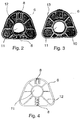
- FIGS. 2 to 4 show the structures of the mounting plate 6.
- FIG. 2 shows a top view of the side of the mounting plate 6 directed towards the upper frame part or lower frame part 1 of the articulator.
- the mounting plate has an opening 11 into which the magnet 3 engages.
- a circular shape of the opening is shown here by way of example, but openings of any shape are possible in principle, although the shape of the opening and the shape of the magnet must match.
- the mounting plate has depressions 8 which serve to receive the positioning bolts attached to the upper frame part or lower frame part 1 of the articulator. Some of the depressions can also be designed in the form of an elastic elongated hole, which on the one hand makes fitting easier and on the other hand still ensures secure positioning.
- the mounting plate is preferably made in the form of a plastic part and therefore expediently has reinforcing webs 12.
- Figure 3 shows the mounting plate 6 of Figure 2 from its other side, namely the side facing the plaster model.
- the circumferential projecting edge 10 can be seen, against which the metal plate 9 (not shown here), which is placed in the opening 11 from this side, is supported.
- the mounting plate 6 can be provided on this side with protruding structures 13 which facilitate plastering of the plaster model.
- Figure 4 shows a modified embodiment of the mounting plate. It is shown here in the form of a plan view of the side facing the upper frame part or lower frame part of the articulator.
- the embodiment shown here has a plurality of adjacent recesses 8 for receiving the positioning bolts, which are attached to the frame of the articulator.
- the depressions can optionally also have different diameters. Due to the large number of recesses 8, the use of the same mounting plate for articulators with different positions is possible Positioning bolts possible. This also makes it easier to convert existing articulators.
- the invention described here provides the user with a magnetic holder, which he can use in conventional articulators instead of the conventional screw connection. This is a very practical and easy-to-implement solution, since the changeover is carried out in the simplest way by unscrewing the previous screw connection and inserting the magnet holder. It is also inexpensive because the magnetic holder according to the invention and the correspondingly designed mounting plate consist of only a few individual parts.
Landscapes
- Health & Medical Sciences (AREA)
- Oral & Maxillofacial Surgery (AREA)
- Dentistry (AREA)
- Epidemiology (AREA)
- Life Sciences & Earth Sciences (AREA)
- Animal Behavior & Ethology (AREA)
- General Health & Medical Sciences (AREA)
- Public Health (AREA)
- Veterinary Medicine (AREA)
- Dental Prosthetics (AREA)
Applications Claiming Priority (2)
| Application Number | Priority Date | Filing Date | Title |
|---|---|---|---|
| DE19508555 | 1995-03-10 | ||
| DE19508555A DE19508555C1 (de) | 1995-03-10 | 1995-03-10 | Auswechselbare Magnethalterung mit entsprechend ausgebildeter Montageplatte für alle gängigen Dentalartikulatoren |
Publications (3)
| Publication Number | Publication Date |
|---|---|
| EP0736289A2 true EP0736289A2 (fr) | 1996-10-09 |
| EP0736289A3 EP0736289A3 (fr) | 1998-05-06 |
| EP0736289B1 EP0736289B1 (fr) | 2003-10-08 |
Family
ID=7756246
Family Applications (1)
| Application Number | Title | Priority Date | Filing Date |
|---|---|---|---|
| EP96103243A Expired - Lifetime EP0736289B1 (fr) | 1995-03-10 | 1996-03-02 | Support magnétique échangeable comportant une plaque de montage à forme correspondante pour tous les articulateurs dentaires usuels |
Country Status (4)
| Country | Link |
|---|---|
| US (1) | US5730593A (fr) |
| EP (1) | EP0736289B1 (fr) |
| AT (1) | ATE251425T1 (fr) |
| DE (2) | DE19508555C1 (fr) |
Families Citing this family (8)
| Publication number | Priority date | Publication date | Assignee | Title |
|---|---|---|---|---|
| CA2276028A1 (fr) | 1998-06-23 | 1999-12-23 | Thomas P. Warner | Cartouche prophylactique dentaire jetable |
| US6210160B1 (en) * | 1998-11-12 | 2001-04-03 | Shiken Corporation | Cover for working cast and articulator |
| US7101182B2 (en) * | 2002-07-22 | 2006-09-05 | Garrison Dental Solutions | Dental apparatus |
| US20040126731A1 (en) * | 2002-10-08 | 2004-07-01 | Tbl Partnership | Clutch transfer device |
| US20100255445A1 (en) * | 2007-10-03 | 2010-10-07 | Bernard Gantes | Assisted dental implant treatment |
| IL192008A0 (en) * | 2008-06-05 | 2009-02-11 | Master Tiv Madar Ltd | Accessory for a dental model articulator |
| DE102012111024A1 (de) * | 2012-11-15 | 2014-05-15 | Merz Dental Gmbh | Vorrichtung zur Lagefixierung eines Formkörpers, sowie geeignetes Verfahren hierfür |
| ES2891794B2 (es) | 2020-07-24 | 2022-06-15 | Trimag System S L | Dispositivo de confeccion, duplicacion y fijacion de modelos dentales en articulador |
Citations (3)
| Publication number | Priority date | Publication date | Assignee | Title |
|---|---|---|---|---|
| DE8806485U1 (de) * | 1988-05-18 | 1988-08-04 | Schreiber, Hans, Dr. Dr., 6940 Weinheim | Bausatz zum Einartikulieren von Kiefermodellen |
| DE3918495A1 (de) * | 1989-06-07 | 1990-12-13 | Zeiser Manfred P | Artikulator fuer die zahntechnik sowie arbeitsverfahren damit |
| DE4235959A1 (de) * | 1992-10-24 | 1994-04-28 | Sam Praezisionstechnik Gmbh | Modellträgersockel in Form einer Modellträgerplatte |
Family Cites Families (7)
| Publication number | Priority date | Publication date | Assignee | Title |
|---|---|---|---|---|
| US3221408A (en) * | 1961-12-01 | 1965-12-07 | Joseph V Scullin | Dental model holder |
| US3653126A (en) * | 1971-04-29 | 1972-04-04 | Gorm P Hansen | Dental articulator model mounting means |
| DE2551189C2 (de) * | 1975-03-15 | 1982-02-11 | Mack, Heinz, 8000 München | Montageplatte für Dental-Artikulatoren |
| DE3135122A1 (de) * | 1980-09-05 | 1982-04-08 | Heinz 8000 München Mack | "dental-artikulator" |
| DE3237229A1 (de) * | 1982-10-07 | 1984-04-12 | Gerfried 8450 Amberg Scharl | Modellsockel zur herstellung von zahnersatz |
| DE4118140C2 (de) * | 1991-06-03 | 1995-05-11 | Hanns Joachim Feyen | Anordnung zur lösbaren Befestigung von Gipsmodellen in einer Handhabungsvorrichtung |
| DE4239910A1 (de) * | 1992-11-27 | 1994-06-01 | Schreiber Hans | Plattensatz zum Gleichschalten unterschiedlicher Artikulatoren |
-
1995
- 1995-03-10 DE DE19508555A patent/DE19508555C1/de not_active Expired - Fee Related
-
1996
- 1996-03-02 EP EP96103243A patent/EP0736289B1/fr not_active Expired - Lifetime
- 1996-03-02 DE DE59610757T patent/DE59610757D1/de not_active Expired - Lifetime
- 1996-03-02 AT AT96103243T patent/ATE251425T1/de not_active IP Right Cessation
- 1996-03-05 US US08/611,070 patent/US5730593A/en not_active Expired - Lifetime
Patent Citations (3)
| Publication number | Priority date | Publication date | Assignee | Title |
|---|---|---|---|---|
| DE8806485U1 (de) * | 1988-05-18 | 1988-08-04 | Schreiber, Hans, Dr. Dr., 6940 Weinheim | Bausatz zum Einartikulieren von Kiefermodellen |
| DE3918495A1 (de) * | 1989-06-07 | 1990-12-13 | Zeiser Manfred P | Artikulator fuer die zahntechnik sowie arbeitsverfahren damit |
| DE4235959A1 (de) * | 1992-10-24 | 1994-04-28 | Sam Praezisionstechnik Gmbh | Modellträgersockel in Form einer Modellträgerplatte |
Also Published As
| Publication number | Publication date |
|---|---|
| DE19508555C1 (de) | 1996-06-27 |
| EP0736289A3 (fr) | 1998-05-06 |
| EP0736289B1 (fr) | 2003-10-08 |
| US5730593A (en) | 1998-03-24 |
| DE59610757D1 (de) | 2003-11-13 |
| ATE251425T1 (de) | 2003-10-15 |
Similar Documents
| Publication | Publication Date | Title |
|---|---|---|
| DE29905687U1 (de) | Trageinrichtung | |
| EP0736289B1 (fr) | Support magnétique échangeable comportant une plaque de montage à forme correspondante pour tous les articulateurs dentaires usuels | |
| DE3511928C1 (de) | Einstellbarer Primaersockel fuer zahntechnische Artikulatoren | |
| DE3202997C1 (de) | Zahntechnischer Artikulator | |
| DE3237229A1 (de) | Modellsockel zur herstellung von zahnersatz | |
| DE29509214U1 (de) | Auswechselbare Magnethalterung mit entsprechend ausgebildeter Montageplatte für alle gängigen Dentalartikulatoren | |
| DE4324058C2 (de) | Hohlkörper für die Elektroinstallation | |
| DE3544847C2 (de) | Einbaurahmen | |
| DE4222656A1 (de) | Elektrische Steckdose | |
| DE19547137C2 (de) | Vorrichtung zur Halterung von Zahn- und/oder Kiefermodellteilen | |
| DE4206835C2 (de) | Montageplatte für einen Artikulator | |
| DE4017349C1 (en) | Bucket and spade play set - incorporates sand-moulds, rake and sieve | |
| DE29506480U1 (de) | Zahnmodell-Träger | |
| DE2856084C2 (de) | Vorrichtung zur lösbaren Verbindung eines Modells mit einem in einem Gebiflartikulator aufnehmbaren oder angeordneten Gipssockel | |
| DE4013076A1 (de) | Kuevette und verfahren zum herstellen von modellduplikaten | |
| DE4241841C1 (de) | Aufspannvorrichtung für wenigstens zwei miteinander fluchtend ausgerichtete Aggregate | |
| DE10141573B4 (de) | Verfahren und Vorrichtung zum Fixieren eines Gebissmodells auf einer Tragplatte mit Haltestiften | |
| EP0389805B1 (fr) | Pupitre de commande, en particulier pour des commandes de machines | |
| DE9212839U1 (de) | Einrichtteleskop | |
| DE3519268C2 (de) | Multirastersystem und Vorrichtung zur Herstellung eines Mikrorastersystems für Mosaikbilder in Schaltwarten | |
| DE8806485U1 (de) | Bausatz zum Einartikulieren von Kiefermodellen | |
| DE9002467U1 (de) | Vorrichtung zur Befestigung einer Vorsatzfront an einem Schubkasten o.dgl. | |
| DE202019105545U1 (de) | Modulares Leitsystem | |
| DE102020101123A1 (de) | Modulare Wand | |
| DE9202861U1 (de) | Modellsockel zur Halterung eines Zahnmodells in einem Artikulator |
Legal Events
| Date | Code | Title | Description |
|---|---|---|---|
| PUAI | Public reference made under article 153(3) epc to a published international application that has entered the european phase |
Free format text: ORIGINAL CODE: 0009012 |
|
| AK | Designated contracting states |
Kind code of ref document: A2 Designated state(s): AT DE FR IT |
|
| PUAL | Search report despatched |
Free format text: ORIGINAL CODE: 0009013 |
|
| AK | Designated contracting states |
Kind code of ref document: A3 Designated state(s): AT DE FR IT |
|
| 17P | Request for examination filed |
Effective date: 19980622 |
|
| 17Q | First examination report despatched |
Effective date: 20020206 |
|
| GRAH | Despatch of communication of intention to grant a patent |
Free format text: ORIGINAL CODE: EPIDOS IGRA |
|
| GRAS | Grant fee paid |
Free format text: ORIGINAL CODE: EPIDOSNIGR3 |
|
| GRAA | (expected) grant |
Free format text: ORIGINAL CODE: 0009210 |
|
| AK | Designated contracting states |
Kind code of ref document: B1 Designated state(s): AT DE FR IT |
|
| PG25 | Lapsed in a contracting state [announced via postgrant information from national office to epo] |
Ref country code: IT Free format text: LAPSE BECAUSE OF FAILURE TO SUBMIT A TRANSLATION OF THE DESCRIPTION OR TO PAY THE FEE WITHIN THE PRE;WARNING: LAPSES OF ITALIAN PATENTS WITH EFFECTIVE DATE BEFORE 2007 MAY HAVE OCCURRED AT ANY TIME BEFORE 2007. THE CORRECT EFFECTIVE DATE MAY BE DIFFERENT FROM THE ONE RECORDED.SCRIBED TIME-LIMIT Effective date: 20031008 Ref country code: FR Free format text: LAPSE BECAUSE OF FAILURE TO SUBMIT A TRANSLATION OF THE DESCRIPTION OR TO PAY THE FEE WITHIN THE PRESCRIBED TIME-LIMIT Effective date: 20031008 |
|
| REF | Corresponds to: |
Ref document number: 59610757 Country of ref document: DE Date of ref document: 20031113 Kind code of ref document: P |
|
| PG25 | Lapsed in a contracting state [announced via postgrant information from national office to epo] |
Ref country code: AT Free format text: LAPSE BECAUSE OF NON-PAYMENT OF DUE FEES Effective date: 20040302 |
|
| PLBE | No opposition filed within time limit |
Free format text: ORIGINAL CODE: 0009261 |
|
| STAA | Information on the status of an ep patent application or granted ep patent |
Free format text: STATUS: NO OPPOSITION FILED WITHIN TIME LIMIT |
|
| 26N | No opposition filed |
Effective date: 20040709 |
|
| EN | Fr: translation not filed | ||
| REG | Reference to a national code |
Ref country code: DE Ref legal event code: R082 Ref document number: 59610757 Country of ref document: DE Representative=s name: MUELLER-BORE & PARTNER PATENTANWAELTE PARTG MB, DE Ref country code: DE Ref legal event code: R082 Ref document number: 59610757 Country of ref document: DE Representative=s name: MUELLER-BORE & PARTNER, PATENTANWAELTE, EUROPE, DE |
|
| PGFP | Annual fee paid to national office [announced via postgrant information from national office to epo] |
Ref country code: DE Payment date: 20150325 Year of fee payment: 20 |
|
| REG | Reference to a national code |
Ref country code: DE Ref legal event code: R071 Ref document number: 59610757 Country of ref document: DE |