EP0735167A2 - Machine de peignage - Google Patents
Machine de peignage Download PDFInfo
- Publication number
- EP0735167A2 EP0735167A2 EP96102426A EP96102426A EP0735167A2 EP 0735167 A2 EP0735167 A2 EP 0735167A2 EP 96102426 A EP96102426 A EP 96102426A EP 96102426 A EP96102426 A EP 96102426A EP 0735167 A2 EP0735167 A2 EP 0735167A2
- Authority
- EP
- European Patent Office
- Prior art keywords
- tear
- rollers
- machine according
- combing machine
- bearings
- Prior art date
- Legal status (The legal status is an assumption and is not a legal conclusion. Google has not performed a legal analysis and makes no representation as to the accuracy of the status listed.)
- Granted
Links
Images


Classifications
-
- D—TEXTILES; PAPER
- D01—NATURAL OR MAN-MADE THREADS OR FIBRES; SPINNING
- D01G—PRELIMINARY TREATMENT OF FIBRES, e.g. FOR SPINNING
- D01G19/00—Combing machines
- D01G19/06—Details
- D01G19/26—Driving arrangements
-
- D—TEXTILES; PAPER
- D01—NATURAL OR MAN-MADE THREADS OR FIBRES; SPINNING
- D01G—PRELIMINARY TREATMENT OF FIBRES, e.g. FOR SPINNING
- D01G19/00—Combing machines
- D01G19/06—Details
- D01G19/14—Drawing-off and delivery apparatus
- D01G19/18—Roller, or roller and apron, devices, e.g. operating to draw-off fibres continuously
- D01G19/20—Roller, or roller and apron, devices, e.g. operating to draw-off fibres continuously operating to draw-off fibres intermittently
Definitions
- the present invention relates to a combing machine according to the preamble of claim 1.
- Modern combers go back to the technological constructions of John William Nasmith around 1920. They have vibrating pliers, reversing tear-off cylinders, round combs and cleaning brushes. The fiber structure is separated by a simultaneous swinging back of the pliers and a forward rotation of the tear-off cylinders. The tear-off cylinders then reverse and feed the sliver back in such a way that the newly combed fiber beard can be placed on it. There is the "soldering", as the expert says.
- the amount of combing excretion is determined by the tear-off length, the so-called "Ecartement".
- the ecartement is the distance between the clamping line of the inner tear-off cylinders and the clamp line of the upper and lower pliers, which results when the vibrating pliers come closest to the clamp line of the inner tear-off cylinders.
- the size of the ecartement determines the length of the fiber beard, which hangs freely when the pliers are closed and is combed by the round comb. With a constant fiber length distribution in the fiber beard, the larger the ecartement, the more fibers are combed out. The excretion of combs increases with the enlargement of the ecartement and decreases accordingly with a reduction in the ecartement.
- an adjustment of the compartment is also provided by pivoting the upper, inner tear-off roller about the axis of rotation of the lower tear-off roller, so as to reduce the aforementioned workload at least with only slight adjustments of the compartment .
- Combing machines are known in particular in the wool processing industry which do not adhere to Nasmith's design template (see UK PS 1 207 441) but to the older version by Heilmann.
- the tear-off movement does not take place by swinging the pliers back but only by a corresponding movement of the tear-off rollers to the front.
- the pliers bob up and down to the rhythm of the machine rotation.
- the tear-off cylinders move both back and forth in the machine rhythm both rotationally and translationally.
- the axis of the tear-off cylinder thus moves outwards and inwards once per machine cycle.
- the ecartement was determined by adjusting the inner reversal point of the tear-off roller rocker.
- the object of the invention is to provide those combiners of the type mentioned at the outset with those improvements which permit simple and rapid adjustment and adjustment of the compartment without necessarily having to shut down the machine.
- the adjustment of the Ecartementes is achieved according to the invention by an independent, common displacement of all escaping tear-off cylinders.
- the shift can be linear, on an arc or on any other suitable curve. Relative to the machine movement and the combing process, the displacement of the tear-off cylinders is negligible and the adjustment is independent of the machine cycle.
- the functions of the tear-off cylinder (removal and soldering) continue to be carried out exclusively by their known pilgrim-like rotary movement.
- a pliers head 3 is pivotally mounted about a pliers axis 2, to which a round comb 4 with a needle segment 5 is assigned.
- the pliers head 3 interacts with tear-off rollers 6.
- the fiber assembly 7 supplied for combing is continuously fed to the pliers head 3 from a winding roll (not shown).
- the preceding end of the batting emerging from the pliers, the so-called fiber beard 10 is conveyed soldered to the crest 11 held between the tear-off rollers 6 and fed back in vocational steps and torn off from the trailing batting 7.
- the needle segment 5 is cleaned from the combs combed out of the only freely hanging fiber beard 10 by a brush roller, not shown, rotating in the same direction at a higher speed.
- the pliers head 3 has lower pliers 13 articulated on the pliers axis 2 and upper pliers 14 pivotably mounted thereon.
- the lower jaw 13 essentially consists of a lower jaw arm 15 and a lower jaw plate 16 fastened thereon.
- the upper jaw 14 is pivotably mounted on lateral pivot pins 17 of the lower jaw 13.
- a feed roller 18 for the cotton 7 which converts the continuous cotton feed into a discontinuous one.
- the intermittent drive of the feed roller 18 takes place in rhythm with the movement of the pliers head by means of a ratchet mechanism not shown, but described in detail in US Pat. No. 3,479,699.
- the upper pliers 14 basically consist of an upper pliers arm 20 articulated on the pivot pin 17 and an upper pliers plate 21 fastened thereon as well as a lever 9 firmly connected to it. Furthermore, the upper pliers 14 are provided with an adjustable piercing comb 19 which does not have those fibers of the fiber beard 10 have the length of the tear-off distance (Ecartement), retains from being drawn into the tear-off rollers 6.
- the upper pliers plate 21 can be pivoted in the rhythm of movement of the pliers head 3 against the lower pliers plate 16 or away from it, and in such a way that the pliers head 3 is open in the outer end position (shown in FIG.
- the tear-off rollers 6 are formed by two pairs of tear-off rollers 6 ′, 6 ′′, each of which has a lower, driven and an upper tear-off roller 23 and 24, respectively. Their periodic mit-like forward and backward movement causes the ridge 11 to be removed in the forward direction (in the direction of the arrow 25) and, with the return, a soldering with the combed fiber beard 10 supplied by the pliers head 3.
- the combing machine is driven by a motor 31, which drives a clock shaft 33 via a reduction gear 32. With each revolution of the clock shaft 33, the machine executes a backlash.
- the lower tear-off rollers 23 are likewise driven synchronously by the clock shaft 33 via a vocational step mechanism 37 known per se, so that their forward and backward movement takes place during a comb play as in the known combing machines.
- the tear-off rollers 6 are rotatably mounted in a bearing block 41 and, as mentioned, driven by the vocational step mechanism 37. A drive by a reversible electric motor is also conceivable.
- the bearing block 41 sits firmly on a machine part 61, which is connected in a rotationally fixed manner to a lever 43 via a pivot shaft 42 mounted in the machine stand 1.
- the tear-off rollers 6 are moved against or away from the pliers head 3 and the clamping line 44 of the inner tear-off roller pair 6 ′′ is displaced on an arcuate path 45.
- the ecartement E to the clamping line 46 (between the lower and upper pliers 13 or 14) of the pliers head 3 can thus be changed when the head 3 assumes its outer end position shown in FIG. 1. 1 also shows the tear-off roller 6 in its greatest possible approximation to the pliers head 3, in which the compartment E, for which the machine is designed, is the smallest.
- the ecartement E increases up to a constructively defined maximum value, which can be determined by an adjustable or fixed stop which limits the pivot path of the shaft 42.
- the adjustment or pivoting of the shaft 42 is generated by means of a threaded spindle 47 rotatably mounted in the machine stand 1, which can be driven by hand or by means of a stepper motor.
- a nut 48 sits on the threaded shaft thereof, with an axle pin 49 to which one end of a link 50 is articulated.
- the other handlebar end is articulated on a pivot pin 51 of the lever 43.
- the threaded spindle 47 and the lever 43 are parallel when the smallest ecartement E is set and the link 50 is oriented at right angles to their longitudinal central axes. If the spindle 47 is rotated, the nut 48 moves up or down and pivots the shaft 42 by means of the handlebar 50 and the lever 43 by an angle ⁇ , the tear-off rollers 6 being moved into the position shown in broken lines and the size E being enlarged .
- the tear-off rollers 6 - independently of the other movements to be carried out by them for the removal and soldering of the cotton wool - are adjustable in their position relative to the fixed points of the pliers head 3 on an arc-shaped track 45 with a slight curvature, it is possible that To make path 45 of their adjustment path even flatter, linear or otherwise curved.
- the bearing block 41 would then be mounted on a crank arm (instead of a pivot lever) or in appropriately shaped guide curves and fastened to the machine stand 1.
- the adjustment movement for the tear-off rollers 6 could take place instead of by hand by means of a stepping motor with an assigned incremental encoder.
- other mechanical reduction gears are equally suitable.
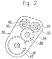
- the driven tear-off rollers 23 each sit in a rotationally fixed manner on a shaft 52 or 53 which is freely rotatably mounted in the bearing block 41. These shafts 52 and 53 are further rotatably mounted in an intermediate gear housing 54 of an intermediate gear 55 fastened to the bearing block 41 (FIG. 2).
- the intermediate gear 55 is the gear connection from the vocational step gear 37 to the shafts 52 and 53.
- a gear 56 or 57 of the same size sits on each of the shafts 52, 53 in a rotationally fixed manner.
- the two gears 56, 57 mesh with an intermediate gear 58 which is freely rotatably mounted in the housing 54 and which in turn meshes with a counter gear 59.
- the intermediate gear housing 54 is pivotally mounted on the shaft 42 'or pivotable about its axis on the machine stand.
- the housing 54 with the shafts 52, 53 and the gear wheels 56, 57, 58 is pivoted about the axis of the shaft 42 'and the counter gear 59.
- the gears 56 to 59 remain in mutual engagement, so that the adjustment can be made while the machine is running.
- a chain transmission or the like can also be used as an intermediate transmission 55.
- the pincer axis 2 represents a fixed bearing for the movable pliers head 3 with respect to which the bearing 41 of the tear-off rollers 6 is adjustable, such a fixed bearing 2 'is also for the combing machine mentioned at the beginning according to UK-PS 1 207 441 the in Direction of the double arrow 60 up and down rocking pliers head 3 available (Fig. 3).
- the adjustability of the tear-off rollers according to the invention also takes place in such a machine with reference to this fixed bearing, in that the tear-off rollers 6 are adjusted and adjusted with their bearing block 41 relative to the rocker arm 61 swinging about their stroke path.
Landscapes
- Engineering & Computer Science (AREA)
- Textile Engineering (AREA)
- Preliminary Treatment Of Fibers (AREA)
- Eye Examination Apparatus (AREA)
Applications Claiming Priority (2)
| Application Number | Priority Date | Filing Date | Title |
|---|---|---|---|
| US08/410,891 US5546636A (en) | 1995-03-27 | 1995-03-27 | Comber machine |
| US410891 | 1995-03-27 |
Publications (3)
| Publication Number | Publication Date |
|---|---|
| EP0735167A2 true EP0735167A2 (fr) | 1996-10-02 |
| EP0735167A3 EP0735167A3 (fr) | 1997-03-12 |
| EP0735167B1 EP0735167B1 (fr) | 2000-07-12 |
Family
ID=23626662
Family Applications (1)
| Application Number | Title | Priority Date | Filing Date |
|---|---|---|---|
| EP96102426A Expired - Lifetime EP0735167B1 (fr) | 1995-03-27 | 1996-02-17 | Machine de peignage |
Country Status (5)
| Country | Link |
|---|---|
| US (1) | US5546636A (fr) |
| EP (1) | EP0735167B1 (fr) |
| AT (1) | ATE194669T1 (fr) |
| DE (1) | DE59605567D1 (fr) |
| GR (1) | GR3034303T3 (fr) |
Cited By (3)
| Publication number | Priority date | Publication date | Assignee | Title |
|---|---|---|---|---|
| DE102006052156A1 (de) * | 2006-11-02 | 2008-05-08 | Oerlikon Textile Gmbh & Co. Kg | Abreißwalzenfixierung |
| CN112048786A (zh) * | 2019-06-05 | 2020-12-08 | 高迪诺工坊股份公司 | 直型精梳机 |
| IT201900008712A1 (it) * | 2019-06-12 | 2020-12-12 | Officine Gaudino S P A | Macchina pettinatrice rettilinea munita di gruppo strappatore perfezionato |
Families Citing this family (5)
| Publication number | Priority date | Publication date | Assignee | Title |
|---|---|---|---|---|
| IT1317208B1 (it) * | 2000-04-11 | 2003-05-27 | Vouk S P A Officine Meccanotes | Gruppo di comando per l'azionamento a passo del pellegrino deicilindri strappatori in una macchina pettinatrice |
| CN103046171A (zh) * | 2012-12-23 | 2013-04-17 | 经纬纺织机械股份有限公司 | 精梳机落棉隔距微调结构 |
| JP6194871B2 (ja) * | 2014-11-06 | 2017-09-13 | 株式会社豊田自動織機 | コーマにおけるラップ継ぎ装置 |
| CN108796676B (zh) * | 2018-08-29 | 2023-04-25 | 金陵科技学院 | 一种绢纺圆梳用副夹板加压输送机构 |
| IT201900005608A1 (it) * | 2019-04-11 | 2020-10-11 | Marzoli Machines Textile Srl | Pettinatrice di una linea di preparazione alla filatura |
Citations (4)
| Publication number | Priority date | Publication date | Assignee | Title |
|---|---|---|---|---|
| GB345241A (en) * | 1929-12-18 | 1931-03-18 | John William Nasmith | Improvements in or relating to combing machines for textile fibres |
| FR825901A (fr) * | 1937-03-08 | 1938-03-17 | Nasmith S Inv S Ltd | Perfectionnements aux peigneuses |
| US2558706A (en) * | 1945-01-04 | 1951-06-26 | Terrell Mach Co | Combing machine |
| US3604063A (en) * | 1969-05-02 | 1971-09-14 | Maremont Corp | Textile comber detaching roll drive |
Family Cites Families (3)
| Publication number | Priority date | Publication date | Assignee | Title |
|---|---|---|---|---|
| US3479699A (en) * | 1966-10-10 | 1969-11-25 | Maremont Corp | Combers |
| FR91777E (fr) * | 1967-01-09 | 1968-08-09 | Schlumberger Cie N | Perfectionnements aux peigneuses rectilignes |
| US3600758A (en) * | 1969-05-02 | 1971-08-24 | Maremont Corp | Textile comber nipper drive |
-
1995
- 1995-03-27 US US08/410,891 patent/US5546636A/en not_active Expired - Fee Related
-
1996
- 1996-02-17 DE DE59605567T patent/DE59605567D1/de not_active Expired - Fee Related
- 1996-02-17 EP EP96102426A patent/EP0735167B1/fr not_active Expired - Lifetime
- 1996-02-17 AT AT96102426T patent/ATE194669T1/de not_active IP Right Cessation
-
2000
- 2000-08-31 GR GR20000401990T patent/GR3034303T3/el unknown
Patent Citations (4)
| Publication number | Priority date | Publication date | Assignee | Title |
|---|---|---|---|---|
| GB345241A (en) * | 1929-12-18 | 1931-03-18 | John William Nasmith | Improvements in or relating to combing machines for textile fibres |
| FR825901A (fr) * | 1937-03-08 | 1938-03-17 | Nasmith S Inv S Ltd | Perfectionnements aux peigneuses |
| US2558706A (en) * | 1945-01-04 | 1951-06-26 | Terrell Mach Co | Combing machine |
| US3604063A (en) * | 1969-05-02 | 1971-09-14 | Maremont Corp | Textile comber detaching roll drive |
Cited By (4)
| Publication number | Priority date | Publication date | Assignee | Title |
|---|---|---|---|---|
| DE102006052156A1 (de) * | 2006-11-02 | 2008-05-08 | Oerlikon Textile Gmbh & Co. Kg | Abreißwalzenfixierung |
| CN112048786A (zh) * | 2019-06-05 | 2020-12-08 | 高迪诺工坊股份公司 | 直型精梳机 |
| EP3748051A1 (fr) * | 2019-06-05 | 2020-12-09 | OFFICINE GAUDINO SpA | Peigneuse rectiligne |
| IT201900008712A1 (it) * | 2019-06-12 | 2020-12-12 | Officine Gaudino S P A | Macchina pettinatrice rettilinea munita di gruppo strappatore perfezionato |
Also Published As
| Publication number | Publication date |
|---|---|
| DE59605567D1 (de) | 2000-08-17 |
| ATE194669T1 (de) | 2000-07-15 |
| GR3034303T3 (en) | 2000-12-29 |
| EP0735167A3 (fr) | 1997-03-12 |
| US5546636A (en) | 1996-08-20 |
| EP0735167B1 (fr) | 2000-07-12 |
Similar Documents
| Publication | Publication Date | Title |
|---|---|---|
| EP1586682B1 (fr) | Entraînement pour une peigneuse | |
| DE102012011030A1 (de) | Vorrichtung an einer Kämmmaschine mit einer Antriebsvorrichtung zur Erzeugung einer Pilgerschrittbewegung für die Abreißwalzen | |
| EP0735167B1 (fr) | Machine de peignage | |
| DE19713225B4 (de) | Abreiss- und Lötvorrichtung an einer Kämmaschine | |
| EP2307597B1 (fr) | Dispositif de peignage destiné à une matière fibreuse | |
| EP0967307B1 (fr) | Pince d'une machine de peignage | |
| DE2531124C3 (de) | Antriebsvorrichtung für die Abreißwalzen einer Flach-Kämm-Maschine | |
| DE2636174C3 (de) | Vorrichtung zum Antreiben der Zangenwelle einer Kämmaschine | |
| EP1639162B1 (fr) | Entrainement d'un groupe pince d'une peigneuse | |
| EP2913427A1 (fr) | Peigneuse dotée d'un cylindre d'alimentation entraîné par moteur électrique | |
| DE1510266B1 (de) | Baumwollkaemmaschine | |
| EP3263751A1 (fr) | Dispositif pour une peigneuse | |
| DE2835185B1 (de) | Vorrichtung zum Antrieb des Fadengebers an Mehrkopf-Stickmaschinen | |
| EP4176114A1 (fr) | Procédé pour faire fonctionner une peigneuse pour préparation de filage, et peigneuse | |
| EP0761851A1 (fr) | Machine de peignage | |
| EP0735168A2 (fr) | Machine de peignage | |
| EP0701013A1 (fr) | Appareil de commande dans une machine de peignage | |
| DE515742C (de) | Kaemm-Maschine | |
| DE1510266C (de) | Baumwollkammaschine | |
| DE102006016385B4 (de) | Kämmmaschine mit Rundkamm und schwingender Zange | |
| DE19536009A1 (de) | Antriebsvorrichtung für eine auf dem Zangenapparat einer Wollkämmaschine angeordneten, umlaufenden Speisekammanordnung | |
| DE491671C (de) | Flachkaemmaschine | |
| CH717419B1 (de) | Kämmmaschine für die Spinnereivorbereitung. | |
| DE102021126664A1 (de) | Kämmmaschine | |
| EP4245897A1 (fr) | Peigneuse dotée d'un réglage amélioré de l'ouverture de pince supérieure |
Legal Events
| Date | Code | Title | Description |
|---|---|---|---|
| PUAI | Public reference made under article 153(3) epc to a published international application that has entered the european phase |
Free format text: ORIGINAL CODE: 0009012 |
|
| AK | Designated contracting states |
Kind code of ref document: A2 Designated state(s): AT CH DE FR GB GR IT LI |
|
| PUAL | Search report despatched |
Free format text: ORIGINAL CODE: 0009013 |
|
| AK | Designated contracting states |
Kind code of ref document: A3 Designated state(s): AT CH DE FR GB GR IT LI |
|
| RAP1 | Party data changed (applicant data changed or rights of an application transferred) |
Owner name: HOLLINGSWORTH SACO LOWELL, INC. |
|
| RIN1 | Information on inventor provided before grant (corrected) |
Inventor name: MEILE, HANS-PETER Inventor name: MANDL, GERHARD, DR. |
|
| 17P | Request for examination filed |
Effective date: 19970826 |
|
| GRAG | Despatch of communication of intention to grant |
Free format text: ORIGINAL CODE: EPIDOS AGRA |
|
| 17Q | First examination report despatched |
Effective date: 19991005 |
|
| RAP1 | Party data changed (applicant data changed or rights of an application transferred) |
Owner name: JOHN D. HOLLINGSWORTH ON WHEELS, INC. |
|
| GRAG | Despatch of communication of intention to grant |
Free format text: ORIGINAL CODE: EPIDOS AGRA |
|
| GRAH | Despatch of communication of intention to grant a patent |
Free format text: ORIGINAL CODE: EPIDOS IGRA |
|
| GRAH | Despatch of communication of intention to grant a patent |
Free format text: ORIGINAL CODE: EPIDOS IGRA |
|
| GRAA | (expected) grant |
Free format text: ORIGINAL CODE: 0009210 |
|
| AK | Designated contracting states |
Kind code of ref document: B1 Designated state(s): AT CH DE FR GB GR IT LI |
|
| REF | Corresponds to: |
Ref document number: 194669 Country of ref document: AT Date of ref document: 20000715 Kind code of ref document: T |
|
| REG | Reference to a national code |
Ref country code: CH Ref legal event code: EP |
|
| REF | Corresponds to: |
Ref document number: 59605567 Country of ref document: DE Date of ref document: 20000817 |
|
| ET | Fr: translation filed | ||
| REG | Reference to a national code |
Ref country code: CH Ref legal event code: NV Representative=s name: TROESCH SCHEIDEGGER WERNER AG |
|
| ITF | It: translation for a ep patent filed |
Owner name: STUDIO TORTA S.R.L. |
|
| GBT | Gb: translation of ep patent filed (gb section 77(6)(a)/1977) |
Effective date: 20000925 |
|
| PG25 | Lapsed in a contracting state [announced via postgrant information from national office to epo] |
Ref country code: GB Free format text: LAPSE BECAUSE OF NON-PAYMENT OF DUE FEES Effective date: 20010217 |
|
| PGFP | Annual fee paid to national office [announced via postgrant information from national office to epo] |
Ref country code: CH Payment date: 20010221 Year of fee payment: 6 Ref country code: AT Payment date: 20010221 Year of fee payment: 6 |
|
| PG25 | Lapsed in a contracting state [announced via postgrant information from national office to epo] |
Ref country code: GR Free format text: LAPSE BECAUSE OF NON-PAYMENT OF DUE FEES Effective date: 20010228 |
|
| PGFP | Annual fee paid to national office [announced via postgrant information from national office to epo] |
Ref country code: DE Payment date: 20010322 Year of fee payment: 6 |
|
| PLBE | No opposition filed within time limit |
Free format text: ORIGINAL CODE: 0009261 |
|
| STAA | Information on the status of an ep patent application or granted ep patent |
Free format text: STATUS: NO OPPOSITION FILED WITHIN TIME LIMIT |
|
| 26N | No opposition filed | ||
| GBPC | Gb: european patent ceased through non-payment of renewal fee |
Effective date: 20010217 |
|
| PG25 | Lapsed in a contracting state [announced via postgrant information from national office to epo] |
Ref country code: FR Free format text: LAPSE BECAUSE OF NON-PAYMENT OF DUE FEES Effective date: 20011031 |
|
| REG | Reference to a national code |
Ref country code: FR Ref legal event code: ST |
|
| PG25 | Lapsed in a contracting state [announced via postgrant information from national office to epo] |
Ref country code: AT Free format text: LAPSE BECAUSE OF NON-PAYMENT OF DUE FEES Effective date: 20020217 |
|
| PG25 | Lapsed in a contracting state [announced via postgrant information from national office to epo] |
Ref country code: LI Free format text: LAPSE BECAUSE OF NON-PAYMENT OF DUE FEES Effective date: 20020228 Ref country code: CH Free format text: LAPSE BECAUSE OF NON-PAYMENT OF DUE FEES Effective date: 20020228 |
|
| PG25 | Lapsed in a contracting state [announced via postgrant information from national office to epo] |
Ref country code: DE Free format text: LAPSE BECAUSE OF NON-PAYMENT OF DUE FEES Effective date: 20020903 |
|
| REG | Reference to a national code |
Ref country code: CH Ref legal event code: PL |
|
| PG25 | Lapsed in a contracting state [announced via postgrant information from national office to epo] |
Ref country code: IT Free format text: LAPSE BECAUSE OF NON-PAYMENT OF DUE FEES;WARNING: LAPSES OF ITALIAN PATENTS WITH EFFECTIVE DATE BEFORE 2007 MAY HAVE OCCURRED AT ANY TIME BEFORE 2007. THE CORRECT EFFECTIVE DATE MAY BE DIFFERENT FROM THE ONE RECORDED. Effective date: 20050217 |