EP0732478B1 - Handversiegelungsvorrichtung - Google Patents
Handversiegelungsvorrichtung Download PDFInfo
- Publication number
- EP0732478B1 EP0732478B1 EP96890038A EP96890038A EP0732478B1 EP 0732478 B1 EP0732478 B1 EP 0732478B1 EP 96890038 A EP96890038 A EP 96890038A EP 96890038 A EP96890038 A EP 96890038A EP 0732478 B1 EP0732478 B1 EP 0732478B1
- Authority
- EP
- European Patent Office
- Prior art keywords
- free end
- extension arm
- sealing
- boom
- arm
- Prior art date
- Legal status (The legal status is an assumption and is not a legal conclusion. Google has not performed a legal analysis and makes no representation as to the accuracy of the status listed.)
- Expired - Lifetime
Links
- 238000007789 sealing Methods 0.000 title claims abstract description 65
- 239000011521 glass Substances 0.000 claims description 6
- 230000002093 peripheral effect Effects 0.000 claims 3
- 150000001875 compounds Chemical class 0.000 description 11
- 238000010276 construction Methods 0.000 description 7
- 230000008878 coupling Effects 0.000 description 5
- 238000010168 coupling process Methods 0.000 description 5
- 238000005859 coupling reaction Methods 0.000 description 5
- 239000000565 sealant Substances 0.000 description 4
- 230000002996 emotional effect Effects 0.000 description 1
- 230000002349 favourable effect Effects 0.000 description 1
- 239000004848 polyfunctional curative Substances 0.000 description 1
- 230000000284 resting effect Effects 0.000 description 1
- 239000000725 suspension Substances 0.000 description 1
- 238000011144 upstream manufacturing Methods 0.000 description 1
Images

Classifications
-
- B—PERFORMING OPERATIONS; TRANSPORTING
- B05—SPRAYING OR ATOMISING IN GENERAL; APPLYING FLUENT MATERIALS TO SURFACES, IN GENERAL
- B05B—SPRAYING APPARATUS; ATOMISING APPARATUS; NOZZLES
- B05B15/00—Details of spraying plant or spraying apparatus not otherwise provided for; Accessories
- B05B15/60—Arrangements for mounting, supporting or holding spraying apparatus
- B05B15/62—Arrangements for supporting spraying apparatus, e.g. suction cups
-
- B—PERFORMING OPERATIONS; TRANSPORTING
- B05—SPRAYING OR ATOMISING IN GENERAL; APPLYING FLUENT MATERIALS TO SURFACES, IN GENERAL
- B05C—APPARATUS FOR APPLYING FLUENT MATERIALS TO SURFACES, IN GENERAL
- B05C17/00—Hand tools or apparatus using hand held tools, for applying liquids or other fluent materials to, for spreading applied liquids or other fluent materials on, or for partially removing applied liquids or other fluent materials from, surfaces
-
- E—FIXED CONSTRUCTIONS
- E06—DOORS, WINDOWS, SHUTTERS, OR ROLLER BLINDS IN GENERAL; LADDERS
- E06B—FIXED OR MOVABLE CLOSURES FOR OPENINGS IN BUILDINGS, VEHICLES, FENCES OR LIKE ENCLOSURES IN GENERAL, e.g. DOORS, WINDOWS, BLINDS, GATES
- E06B3/00—Window sashes, door leaves, or like elements for closing wall or like openings; Layout of fixed or moving closures, e.g. windows in wall or like openings; Features of rigidly-mounted outer frames relating to the mounting of wing frames
- E06B3/66—Units comprising two or more parallel glass or like panes permanently secured together
- E06B3/673—Assembling the units
- E06B3/67339—Working the edges of already assembled units
- E06B3/67343—Filling or covering the edges with synthetic hardenable substances
- E06B3/67347—Filling or covering the edges with synthetic hardenable substances by extrusion techniques
Definitions
- the invention relates to a device for filling the edge joint of insulating glass panes with sealing compound, with a sealing nozzle to be moved by hand along the edge joint, injected from the sealing compound into the edge joint is, and with a holder for the sealing nozzle and the lines leading to it for the components of the sealing compound.
- the person who is sealing executes the sealing nozzle, which usually also a mixing device ("mixing trumpet”) for mixing the two components (basic component and hardener) of the sealing compound is attached, hold and run along the edge joint.
- a mixing device for mixing the two components (basic component and hardener) of the sealing compound is attached, hold and run along the edge joint.
- the invention has for its object a device specify genus mentioned at the beginning, with which a largely weight-free handling of the sealing nozzle with as much as possible large working area is possible.
- the device according to the invention is a considerable Work area guaranteed because the cantilever arm, for example 220 ° back and forth and the boom, for example, by 270 ° and can pivot here, so that with reasonable lengths of Cantilever arm and boom (each around 2 m) a radius of the work area of, for example, 4.3 m can be achieved.
- the advantageous mobility of the holder according to the invention for the sealing nozzle it is particularly easy to ensure if according to a proposal of the invention that at the free end of the cantilever is pivotable about the vertical axis a carrier is mounted on which the boom around the horizontal axis is pivotally mounted.
- a stable and space-saving construction results when the beam is U-shaped in cross-section and its web is arranged above the boom.
- a particularly simple and reliable construction, in which the relief of the boom provided according to the invention is reliably realized, results when an arm is rigidly attached to the boom, the free end of which is force-loaded in the sense of a pivoting of the free end of the boom.
- the boom by a spring, in particular a pneumatic cylinder, is loaded. So the force with which the boom is loaded upwards, simply on each required size can be set.
- the arm through an opening provided in the web of the carrier protrudes upwards. This embodiment results in a space-saving Construction in the area of the joint between the cantilever and the boom.
- the sealing nozzle including the mixing device of the two components of the sealant exclusively over the lines at the free end of the boom are suspended, there is a simple construction, wherein moreover, handling the sealing nozzle is not due to additional Means through which this at the free end of the boom is attached, is hindered.
- a switch is provided at the free end of the boom, when actuated, the pneumatic cylinder with pressure accordingly the highest and / or lowest possible position of the free End of the boom is applied. That way the sealing nozzle including the mixing device Not used in an overhead resting position and at long periods of non-use can be lowered to immerse yourself in a freezer, for example.
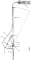
- the device according to the invention consists of a cantilever 1, a boom 2, a manual sealing nozzle 3 with a mixing device 4, and from a supply station 5 for the components the sealant.
- the type of storage station 5 is for the invention is not essential. Instead of that shown in Fig. 1
- Embodiment of a supply station 5 for the component the sealant with drums and drum pumps can for example, a storage station with containers from DE-U-94/07 507 known type (so-called "big bags") provided his.
- lines 6 and 7 provided by which the components of the sealant the mixing device 4 are fed (in the drawing only one line is visible).
- the cantilever 1 is opposite in the area of the supply unit 5 a tripod 8 about a vertical axis 9 e.g. by 220 ° pivotable.
- a carrier pivotable about a vertical axis 12 13 provided at the free end 10 of the horizontal section 11 of the cantilever 1 .
- the carrier 13 has a U-shaped opening which is open at the bottom Cross-sectional shape, i.e. the web of the U-profile of the Carrier 13 faces upwards and is above the inside of the Carrier 13 arranged end of the boom 2 arranged.
- the cantilever side end of the carrier 13 is with a U-shaped Bracket 14 connected, the legs of which at the free end 10 of Section 11 of the cantilever 1 pivotable about the axis 12 are stored.
- the boom 2 is on the carrier 13 about an axis 15 which is essentially is aligned horizontally, between that in FIG. 2 shown, essentially horizontal position and one after bottom-facing position (dashed lines in Fig. 2) pivotable.
- An arm 16 is rigidly connected to the boom 2.
- the arm 16 protrudes through a in the upwardly pointing web of the carrier 13 intended opening upwards.
- Between the end 17 of the carrier 13 and the upper end 18 of the arm 16 is one in the example Pneumatic cylinder 19 acting as a spring clamped.
- the pivot position of the Boom 2 determines the horizontal axis 15 and the combination from sealing nozzle 3 and mixing device 4 for the operator can be made practically weightless.
- a switch 20 is provided at the free end of the boom 2, which controls the pressurization of the pneumatic cylinder 19, with the possibility of operating the switch 20 to act on the pneumatic cylinder 19 so that it Boom 2 in the one shown in FIG. 1, pivoted all the way up Position and / or the boom 2 in the fully lowered Position (shown in dashed lines in Fig. 1) holds.
- the latter position is used, for example, when in breaks the mixing device 4 and the sealing nozzle 3 be placed in a freezer (-25 ° C) to harden to prevent the sealing compound in the sealing nozzle 3.
- Lines 6 and 7 are in the area of the articulated connection between the free end 10 of the horizontal section 11 of the cantilever 1 and the boom 2 in arches 21 upwards deflected.
- rotary couplings 22 are provided to the rotatability of the boom 2 compared to ensure the cantilever 1 (axis 12) are in the lines 6 and 7 . Because of the rotating couplings 22 in combination with the arches 21 are the movements of the boom 2 (pivoting about the axis 12 by up to 270 ° and Swiveling up and down about axis 15) is not hindered.
- the invention can be as follows, for example being represented:
- a hand sealer consists of a crane-like one Cantilever arm 1, which can be rotated about a vertical axis 9 is.
- a boom 2 At the free end 10 of the horizontal section 11 of the cantilever 1 is a boom 2 about a vertical axis 12 and connected pivotably about a horizontal axis 15.
- the supply lines 6, 7 through which the components the sealing compound to a mixing device 4 and promoted a hand sealing nozzle 3 connected to this are attached to the cantilever 1 and the boom 2.
- lines 6 and 7 are laid in arches 21 and have a rotary coupling 22 there, so that the mobility the boom 2 is not hindered.
- the boom 2 is from a pneumatic spring 19 loaded upwards, so that the combination from mixing device 4 and sealing nozzle 3 for an operator performing manual sealing practically are weightless.
Landscapes
- Engineering & Computer Science (AREA)
- Civil Engineering (AREA)
- Structural Engineering (AREA)
- Mechanical Engineering (AREA)
- Seal Device For Vehicle (AREA)
- Closing Of Containers (AREA)
- Glass Compositions (AREA)
- Catching Or Destruction (AREA)
- Coating Apparatus (AREA)
- Control And Other Processes For Unpacking Of Materials (AREA)
- On-Site Construction Work That Accompanies The Preparation And Application Of Concrete (AREA)
- Auxiliary Methods And Devices For Loading And Unloading (AREA)
Applications Claiming Priority (3)
| Application Number | Priority Date | Filing Date | Title |
|---|---|---|---|
| AT47895 | 1995-03-17 | ||
| AT0047895A AT401671B (de) | 1995-03-17 | 1995-03-17 | Handversiegelungsvorrichtung |
| AT478/95 | 1995-03-17 |
Publications (3)
| Publication Number | Publication Date |
|---|---|
| EP0732478A2 EP0732478A2 (de) | 1996-09-18 |
| EP0732478A3 EP0732478A3 (de) | 1997-03-19 |
| EP0732478B1 true EP0732478B1 (de) | 2000-06-07 |
Family
ID=3491685
Family Applications (1)
| Application Number | Title | Priority Date | Filing Date |
|---|---|---|---|
| EP96890038A Expired - Lifetime EP0732478B1 (de) | 1995-03-17 | 1996-03-06 | Handversiegelungsvorrichtung |
Country Status (6)
| Country | Link |
|---|---|
| US (1) | US5759272A (it) |
| EP (1) | EP0732478B1 (it) |
| AT (2) | AT401671B (it) |
| DE (3) | DE29505433U1 (it) |
| ES (1) | ES2147359T3 (it) |
| IT (1) | IT240503Y1 (it) |
Families Citing this family (7)
| Publication number | Priority date | Publication date | Assignee | Title |
|---|---|---|---|---|
| AT401671B (de) * | 1995-03-17 | 1996-11-25 | Lisec Peter | Handversiegelungsvorrichtung |
| US6606837B2 (en) | 2001-08-28 | 2003-08-19 | Cardinal Ig | Methods and devices for simultaneous application of end sealant and sash sealant |
| US6793971B2 (en) * | 2001-12-03 | 2004-09-21 | Cardinal Ig Company | Methods and devices for manufacturing insulating glass units |
| US6884055B2 (en) * | 2002-05-29 | 2005-04-26 | The Boeing Company | Potting compound injection apparatus and method of injecting potting compound into panel cells |
| US20060065115A1 (en) * | 2004-09-27 | 2006-03-30 | Ashley Jimmy D | Fiberglass lamination boom assembly |
| US7878347B2 (en) * | 2007-12-14 | 2011-02-01 | Gorbel, Inc. | Lifting apparatus with compensation means |
| CN112570192B (zh) * | 2020-11-09 | 2022-10-18 | 安徽意达包装有限公司 | 一种木剑端部上胶机 |
Family Cites Families (10)
| Publication number | Priority date | Publication date | Assignee | Title |
|---|---|---|---|---|
| US1745972A (en) * | 1927-01-20 | 1930-02-04 | Louis W Beck | Spray-control appliance |
| DE3818631A1 (de) * | 1988-06-01 | 1989-12-14 | Lenhardt Maschinenbau | Verfahren zum zusammenbauen von isolierglasscheiben, deren einzelne glastafeln paarweise durch einen plastischen abstandhalterrahmen auf abstand gehalten werden |
| DE9014629U1 (de) * | 1990-08-09 | 1991-01-03 | Lenhardt Maschinenbau GmbH, 7531 Neuhausen | Vorrichtung zum automatischen Füllen der Randfuge von Isolierglasscheiben mit einer Dichtmasse |
| DE4033403A1 (de) * | 1990-08-09 | 1992-02-13 | Lenhardt Maschinenbau | Vorrichtung zum automatischen fuellen der randfuge von isolierglasscheiben mit einer dichtmasse |
| DE4232554C1 (de) * | 1992-09-29 | 1994-01-05 | Ver Glaswerke Gmbh | Verfahren zur Herstellung einer mit einem angeformten Rahmen aus einem thermoplastischen Polymer versehenen Glasscheibe und Vorrichtung zur Durchführung des Verfahrens |
| DE4404029A1 (de) * | 1993-10-20 | 1995-08-10 | Lenhardt Maschinenbau | Verfahren und Vorrichtung zum Zusammenbauen von Isolierglasscheiben mit rahmenförmigen Abstandhaltern aus einer plastischen Masse |
| ES2120600T3 (es) * | 1993-11-10 | 1998-11-01 | Peter Lisec | Recipiente para masas fluidas y procedimiento para rellenar y extraer una masa de tales recipientes. |
| US5485960A (en) * | 1994-07-18 | 1996-01-23 | Troudt; Kevin J. | Universal paint sprayer extender |
| DE19505771C1 (de) * | 1995-02-20 | 1996-09-26 | Lenhardt Maschinenbau | Anlage zum Herstellen von Isolierglasscheiben mit Abstandhalter auf Kunststoffbasis |
| AT401671B (de) * | 1995-03-17 | 1996-11-25 | Lisec Peter | Handversiegelungsvorrichtung |
-
1995
- 1995-03-17 AT AT0047895A patent/AT401671B/de not_active IP Right Cessation
- 1995-03-30 DE DE29505433U patent/DE29505433U1/de not_active Expired - Lifetime
-
1996
- 1996-03-06 ES ES96890038T patent/ES2147359T3/es not_active Expired - Lifetime
- 1996-03-06 US US08/611,954 patent/US5759272A/en not_active Expired - Lifetime
- 1996-03-06 AT AT96890038T patent/ATE193745T1/de not_active IP Right Cessation
- 1996-03-06 EP EP96890038A patent/EP0732478B1/de not_active Expired - Lifetime
- 1996-03-06 DE DE59605377T patent/DE59605377D1/de not_active Expired - Lifetime
- 1996-03-07 DE DE19608901A patent/DE19608901C2/de not_active Expired - Fee Related
- 1996-03-14 IT IT1996MI000184U patent/IT240503Y1/it active
Also Published As
| Publication number | Publication date |
|---|---|
| EP0732478A2 (de) | 1996-09-18 |
| ATA47895A (de) | 1996-03-15 |
| ATE193745T1 (de) | 2000-06-15 |
| IT240503Y1 (it) | 2001-04-02 |
| AT401671B (de) | 1996-11-25 |
| EP0732478A3 (de) | 1997-03-19 |
| DE59605377D1 (de) | 2000-07-13 |
| DE19608901C2 (de) | 1998-06-10 |
| US5759272A (en) | 1998-06-02 |
| DE29505433U1 (de) | 1995-06-14 |
| ITMI960184U1 (it) | 1997-09-14 |
| ES2147359T3 (es) | 2000-09-01 |
| DE19608901A1 (de) | 1996-09-26 |
Similar Documents
| Publication | Publication Date | Title |
|---|---|---|
| DE102013203885A1 (de) | Arbeitsgerät mit Stationärmast und Drehkopf | |
| DE2343558C2 (de) | Baggergreifer | |
| DE2401772A1 (de) | Hebebuehne mit schwenkbarer arbeitsplattform | |
| EP0732478B1 (de) | Handversiegelungsvorrichtung | |
| DE19644412A1 (de) | Betonverteilermast für Betonpumpen | |
| EP0141989B1 (de) | Aus rohrförmigen Rutschenschüssen gebildete Rutsche für den transport von Schüttgut | |
| DE102013203886A1 (de) | Arbeitsgerät mit Stationärmast und Drehkopf | |
| DE4009126C1 (it) | ||
| DE852964C (de) | Vorrichtung zum Bewegen von zuruecksetzbaren Rahmen, insbesondere Fensterrahmen | |
| DE69117695T2 (de) | Kran, insbesondere für die Handhabung | |
| DE2720140A1 (de) | Brechvorrichtung zum aufbrechen von oberflaechen auf aluminiumschmelzen o.dgl. | |
| DE4211850C2 (de) | Schiebergehäuse-Öffnungs/Schließvorrichtung bei einer Betonpumpe | |
| DE9111559U1 (de) | Sammelbehälter für Altmaterial | |
| DE20120958U1 (de) | Armlehne für ein Kraftfahrzeug | |
| DE9404670U1 (de) | Verstellbares Gegengewicht für eine Baumaschine und Hydraulikbagger, der mit einem verstellbaren Gegengewicht ausgerüstet ist | |
| DE20316541U1 (de) | Flaschen- oder Becherhalter für ein Kraftfahrzeug | |
| DE19918116C1 (de) | Fördermittel für ein Hängefördersystem | |
| DE102007041040A1 (de) | Nadelmaschine mit Nadelbalkenführung | |
| CH686733A5 (de) | Vorrichtung zum Auftragen von Moertel. | |
| DE4204740C2 (de) | Schutzvorrichtung für einen Schweißarbeitsplatz | |
| DE2802177A1 (de) | Klappbarer wandtisch | |
| DE3326048C2 (de) | Schwenkvorrichtung für eine Hubarbeitsbühne | |
| DE1015717B (de) | Beschlag fuer Schwenk-Kipp-Fluegel von Fenstern, Tueren od. dgl. mit einer Ausstellvorrichtung | |
| DE2219575B2 (de) | Fahrerhaus für Nutzfahrzeuge | |
| DE4424546C2 (de) | Betätigungseinrichtung für die Stopfenstange einer Gießpfanne, Verteilerrinne oder dergleichen |
Legal Events
| Date | Code | Title | Description |
|---|---|---|---|
| PUAI | Public reference made under article 153(3) epc to a published international application that has entered the european phase |
Free format text: ORIGINAL CODE: 0009012 |
|
| AK | Designated contracting states |
Kind code of ref document: A2 Designated state(s): AT BE CH DE DK ES FR GB IT LI NL PT SE |
|
| PUAL | Search report despatched |
Free format text: ORIGINAL CODE: 0009013 |
|
| AK | Designated contracting states |
Kind code of ref document: A3 Designated state(s): AT BE CH DE DK ES FR GB IT LI NL PT SE |
|
| 17P | Request for examination filed |
Effective date: 19970318 |
|
| GRAG | Despatch of communication of intention to grant |
Free format text: ORIGINAL CODE: EPIDOS AGRA |
|
| RTI1 | Title (correction) |
Free format text: MANUAL SEALING DEVICE |
|
| 17Q | First examination report despatched |
Effective date: 19990930 |
|
| GRAG | Despatch of communication of intention to grant |
Free format text: ORIGINAL CODE: EPIDOS AGRA |
|
| GRAH | Despatch of communication of intention to grant a patent |
Free format text: ORIGINAL CODE: EPIDOS IGRA |
|
| GRAH | Despatch of communication of intention to grant a patent |
Free format text: ORIGINAL CODE: EPIDOS IGRA |
|
| GRAA | (expected) grant |
Free format text: ORIGINAL CODE: 0009210 |
|
| AK | Designated contracting states |
Kind code of ref document: B1 Designated state(s): AT BE CH DE DK ES FR GB IT LI NL PT SE |
|
| REF | Corresponds to: |
Ref document number: 193745 Country of ref document: AT Date of ref document: 20000615 Kind code of ref document: T |
|
| REG | Reference to a national code |
Ref country code: CH Ref legal event code: EP |
|
| REF | Corresponds to: |
Ref document number: 59605377 Country of ref document: DE Date of ref document: 20000713 |
|
| ET | Fr: translation filed | ||
| ITF | It: translation for a ep patent filed | ||
| REG | Reference to a national code |
Ref country code: ES Ref legal event code: FG2A Ref document number: 2147359 Country of ref document: ES Kind code of ref document: T3 |
|
| GBT | Gb: translation of ep patent filed (gb section 77(6)(a)/1977) |
Effective date: 20000814 |
|
| PG25 | Lapsed in a contracting state [announced via postgrant information from national office to epo] |
Ref country code: PT Free format text: LAPSE BECAUSE OF FAILURE TO SUBMIT A TRANSLATION OF THE DESCRIPTION OR TO PAY THE FEE WITHIN THE PRESCRIBED TIME-LIMIT Effective date: 20000907 Ref country code: DK Free format text: LAPSE BECAUSE OF FAILURE TO SUBMIT A TRANSLATION OF THE DESCRIPTION OR TO PAY THE FEE WITHIN THE PRESCRIBED TIME-LIMIT Effective date: 20000907 |
|
| PG25 | Lapsed in a contracting state [announced via postgrant information from national office to epo] |
Ref country code: BE Free format text: LAPSE BECAUSE OF NON-PAYMENT OF DUE FEES Effective date: 20010331 |
|
| PLBE | No opposition filed within time limit |
Free format text: ORIGINAL CODE: 0009261 |
|
| STAA | Information on the status of an ep patent application or granted ep patent |
Free format text: STATUS: NO OPPOSITION FILED WITHIN TIME LIMIT |
|
| 26N | No opposition filed | ||
| BERE | Be: lapsed |
Owner name: LISEC PETER Effective date: 20010331 |
|
| REG | Reference to a national code |
Ref country code: GB Ref legal event code: IF02 |
|
| PGFP | Annual fee paid to national office [announced via postgrant information from national office to epo] |
Ref country code: AT Payment date: 20020321 Year of fee payment: 7 |
|
| REG | Reference to a national code |
Ref country code: CH Ref legal event code: NV Representative=s name: TROESCH SCHEIDEGGER WERNER AG |
|
| PG25 | Lapsed in a contracting state [announced via postgrant information from national office to epo] |
Ref country code: AT Free format text: LAPSE BECAUSE OF NON-PAYMENT OF DUE FEES Effective date: 20030306 |
|
| REG | Reference to a national code |
Ref country code: GB Ref legal event code: 732E |
|
| NLS | Nl: assignments of ep-patents |
Owner name: TECNOPAT AG |
|
| REG | Reference to a national code |
Ref country code: FR Ref legal event code: TP |
|
| PGFP | Annual fee paid to national office [announced via postgrant information from national office to epo] |
Ref country code: SE Payment date: 20050310 Year of fee payment: 10 |
|
| PGFP | Annual fee paid to national office [announced via postgrant information from national office to epo] |
Ref country code: NL Payment date: 20050322 Year of fee payment: 10 Ref country code: ES Payment date: 20050322 Year of fee payment: 10 |
|
| PG25 | Lapsed in a contracting state [announced via postgrant information from national office to epo] |
Ref country code: SE Free format text: LAPSE BECAUSE OF NON-PAYMENT OF DUE FEES Effective date: 20060307 Ref country code: ES Free format text: LAPSE BECAUSE OF NON-PAYMENT OF DUE FEES Effective date: 20060307 |
|
| PG25 | Lapsed in a contracting state [announced via postgrant information from national office to epo] |
Ref country code: NL Free format text: LAPSE BECAUSE OF NON-PAYMENT OF DUE FEES Effective date: 20061001 |
|
| EUG | Se: european patent has lapsed | ||
| NLV4 | Nl: lapsed or anulled due to non-payment of the annual fee |
Effective date: 20061001 |
|
| REG | Reference to a national code |
Ref country code: ES Ref legal event code: FD2A Effective date: 20060307 |
|
| REG | Reference to a national code |
Ref country code: DE Ref legal event code: R082 Ref document number: 59605377 Country of ref document: DE Representative=s name: PATENTANWAELTE HENKEL, BREUER & PARTNER, DE |
|
| REG | Reference to a national code |
Ref country code: FR Ref legal event code: PLFP Year of fee payment: 20 |
|
| PGFP | Annual fee paid to national office [announced via postgrant information from national office to epo] |
Ref country code: CH Payment date: 20150319 Year of fee payment: 20 Ref country code: IT Payment date: 20150327 Year of fee payment: 20 Ref country code: DE Payment date: 20150320 Year of fee payment: 20 |
|
| PGFP | Annual fee paid to national office [announced via postgrant information from national office to epo] |
Ref country code: FR Payment date: 20150319 Year of fee payment: 20 Ref country code: GB Payment date: 20150319 Year of fee payment: 20 |
|
| REG | Reference to a national code |
Ref country code: DE Ref legal event code: R071 Ref document number: 59605377 Country of ref document: DE |
|
| REG | Reference to a national code |
Ref country code: CH Ref legal event code: PL |
|
| REG | Reference to a national code |
Ref country code: GB Ref legal event code: PE20 Expiry date: 20160305 |
|
| PG25 | Lapsed in a contracting state [announced via postgrant information from national office to epo] |
Ref country code: GB Free format text: LAPSE BECAUSE OF EXPIRATION OF PROTECTION Effective date: 20160305 |