EP0728958A1 - Kupplungseinrichtung - Google Patents
Kupplungseinrichtung Download PDFInfo
- Publication number
- EP0728958A1 EP0728958A1 EP96102487A EP96102487A EP0728958A1 EP 0728958 A1 EP0728958 A1 EP 0728958A1 EP 96102487 A EP96102487 A EP 96102487A EP 96102487 A EP96102487 A EP 96102487A EP 0728958 A1 EP0728958 A1 EP 0728958A1
- Authority
- EP
- European Patent Office
- Prior art keywords
- cam
- roller
- piston
- clutch device
- pair
- Prior art date
- Legal status (The legal status is an assumption and is not a legal conclusion. Google has not performed a legal analysis and makes no representation as to the accuracy of the status listed.)
- Granted
Links
- 230000007246 mechanism Effects 0.000 claims abstract description 31
- 230000000717 retained effect Effects 0.000 abstract description 3
- 230000005540 biological transmission Effects 0.000 description 8
- 230000009471 action Effects 0.000 description 2
- 238000005452 bending Methods 0.000 description 2
- 238000013459 approach Methods 0.000 description 1
- 230000008901 benefit Effects 0.000 description 1
- 239000000969 carrier Substances 0.000 description 1
- 230000008859 change Effects 0.000 description 1
- 230000009194 climbing Effects 0.000 description 1
- 238000006073 displacement reaction Methods 0.000 description 1
- 230000008030 elimination Effects 0.000 description 1
- 238000003379 elimination reaction Methods 0.000 description 1
- 230000000977 initiatory effect Effects 0.000 description 1
- 238000003754 machining Methods 0.000 description 1
- 238000004519 manufacturing process Methods 0.000 description 1
- 230000009467 reduction Effects 0.000 description 1
Images


Classifications
-
- F—MECHANICAL ENGINEERING; LIGHTING; HEATING; WEAPONS; BLASTING
- F16—ENGINEERING ELEMENTS AND UNITS; GENERAL MEASURES FOR PRODUCING AND MAINTAINING EFFECTIVE FUNCTIONING OF MACHINES OR INSTALLATIONS; THERMAL INSULATION IN GENERAL
- F16D—COUPLINGS FOR TRANSMITTING ROTATION; CLUTCHES; BRAKES
- F16D13/00—Friction clutches
-
- F—MECHANICAL ENGINEERING; LIGHTING; HEATING; WEAPONS; BLASTING
- F16—ENGINEERING ELEMENTS AND UNITS; GENERAL MEASURES FOR PRODUCING AND MAINTAINING EFFECTIVE FUNCTIONING OF MACHINES OR INSTALLATIONS; THERMAL INSULATION IN GENERAL
- F16D—COUPLINGS FOR TRANSMITTING ROTATION; CLUTCHES; BRAKES
- F16D25/00—Fluid-actuated clutches
- F16D25/02—Fluid-actuated clutches with means for actuating or keeping engaged by a force derived at least partially from one of the shafts to be connected
Definitions
- the present invention relates to a clutch device used in an automatic transmission for an automobile.
- a cam roller is arranged between a pair of cam members, each having a cam surface-opposing to each other, and generates an axial thrust by the enlargement of a distance between the cam surfaces caused by the climbing of the cam roller on the cam surfaces due to the relative rotation of the cam members.
- the clutch disk is pushed by this thrust.
- the respective cam surface is formed to have a slope suitable therefor, and one end of the cam surface is formed to be a limiter surface for limiting the displacement of the cam roller.
- An object of the present invention is to solve the above drawback of the related art devices and to provide a clutch device with a cam mechanism free from drag loss upon the switching of the phase from the engaging state wherein the cam mechanism is operative to the releasing state wherein it is inoperative.
- a clutch device which comprises a pair of members disposed at a distance on a common axis and being relatively rotatable to each other on the common axis, a cam mechanism disposed between the pair of members, the cam mechanism comprising a pair of cam elements, each having a cam surface axially opposed to each other, and a cam roller disposed between the opposed cam surfaces, a pushing means for selectively pushing the cam mechanism as a whole onto the axially opposed surface of one of the relatively rotating members to convert a circumferential force to an axial thrust via the cam mechanism so that the relatively rotating members are integrally engaged with each other by the thrust, and a limiter means for limiting the relative rotational movement of the cam elements when the relative rotation occurs between the members in the direction reverse to that wherein the axial thrust is generated between the pair of members.
- Fig. 1 schematically illustrates an overall structure of an automatic transmission for the purpose of explaining where an embodiment of the present invention is used in the automatic transmission.
- AT generally represents an automatic transmission which basically comprises three sets of planetary gear units and plural frictional engagement devices for engaging and disengaging ring gears, sun gears, carriers composing the planetary gear units to and from each other, the details thereof being as follows:
- X 1 represents an input shaft which is connected to an output shaft (not shown) of a torque converter (not shown);
- PG 1 , PG 2 and PG 3 represent a front planetary gear unit, a rear planetary gear unit and an O/D planetary gear unit, respectively;
- R 1 , R 2 and R 3 represent a front planetary ring gear, a rear planetary ring gear and an O/D planetary ring gear, respectively;
- K 1 , K 2 and K 3 represent a front planetary carrier, a rear planetary carrier and an O/D planetary carrier, respectively;
- S 12 represents a front and rear planetary sun gear common to the front and rear planetary gear units, and
- S 3 represents an O/D planetary sun gear;
- C 1 represents a
- CG 1 and CG 2 represent a counter drive gear and a counter driven gear, respectively, which transmit the engine torque to a post-stage mechanism but have no relation to speed changing.
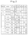
- the table shown in Fig. 2 shows a combination of the engagement and disengagement of frictional engagement elements to attain desired speeds at each range and gear speed.
- Fig. 3 illustrates a side sectional view of an automatic transmission to which a first embodiment of the present invention is built-in, wherein reference numeral 1 represents a piston; 2 represents a cam roller; and 3 represents a pressure plate.
- reference numeral 1 represents a piston
- 2 represents a cam roller
- 3 represents a pressure plate.
- cam grooves 1c and 3c are formed opposing to each other at several locations in the circumferential direction, so that a cam roller 2 is accommodated in the respective pair of opposed cam grooves.
- the cam roller 2 is rotatably retained by a roller cage 4.
- a clutch casing 100 consists of outer and inner halves welded to each other at part A to form an integral body, and coupled to the O/D planetary sun gear S 3 while being rotatable relative to a housing 200.
- the piston 1 is spline-coupled to the clutch casing 100 at part B and is movable to the right and left in the figure in an annular cylinder formed in the interior of the clutch casing 100.
- a hydraulic pressure is supplied into space C between a back surface 1b of the piston 1 and the clutch casing 100 via an oil path 101.
- Clutch disks 5 of the clutch C 3 which are spline-coupled to the O/D planetary carrier K 3 are selectively engaged frictionally with separator plates 6 of the clutch C 3 which are spline-coupled to the clutch casing 100 with the piston 1 through the pressure plate 3.
- a spring 7 is fixedly secured, at the right end thereof, to the clutch casing 100 to always bias the piston 1 to the left in the figure.
- Clutch disks 8 of the brake B 4 which are spline-coupled to the clutch casing 100 are selectively engaged frictionally with separator plates 9 of the brake B 4 which are spline-coupled to the housing 200 with a piston 10 of the brake B 4 .
- Figs. 4A to 4C are cross-sectional views of a cam section as seen parallel to the rotation axis.
- reference numerals 1, 2, 3, 4 and 5 represent the piston, cam roller, pressure plate, roller cage and clutch disk of the clutch C 3 shown in Fig. 3, respectively.
- cam groove 1c and a recess 1d which serves as the limiter according to the present invention are provided.
- a cam groove 3c and a projection 3d projected into the recess 1d of the piston 1 through an opening 4a formed in the roller cage 4 are provided.
- Fig. 4A illustrates a disengaging state wherein the pressure plate 3 and the C 3 clutch disk 5 are apart from each other.
- the C 3 clutch disk 5 splined-coupled to the O/D planetary carrier K 3 moves to the right in the figure, while the piston 1 and the pressure plate 3 are stationary.
- the C 3 clutch disk 5 is coupled to the O/D planetary carrier K 3 and the piston 1 is to the O/D planetary sun gear S 3 , the O/D planetary sun gear S 3 is integral with the O/D planetary carrier K 3 to be rotatable together according to this engagement.
- Fig. 4B illustrates, the piston 1 and the C 3 clutch disk 5 engaged to each other as described.
- the opening 4a of the roller cage 4 is formed to be sufficiently large, no interference occurs between the projection 3d of the pressure plate 3 and the roller cage 4 when the phase is switched from the state shown in Fig. 4A to that shown in Fig. 4B.
- Fig. 4B shows the driving state wherein the engine positively drives the wheels in all of the forward gear speeds except for the fourth gear speed.
- the second and first one-way clutches F 2 , F 1 are idling, respectively, to nullify the engine brake.
- the fourth brake B 4 is actuated to interrupt the rotation of the O/D planetary sun gear S 3 . Since the O/D planetary carrier K 3 is coupled to the O/D planetary ring gear R 3 , the rotational speed of the O/D planetary carrier K 3 temporarily becomes slower.
- the pressure plate 3 engaged with the C 3 clutch disk 5 escapes from the roller 2 in the lefthand direction in the figure, while maintaining the inner surface 1a of the piston 1 apart from the inner surface 3a of the pressure plate 3. Also the piston 1 escapes from the roller 2 in the righthand direction.
- a wall surface 1e of the recess 1d of the piston 1 approaches a wall surface 3e of the projection 3d of the pressure plate 3.
- the recess 1d of the piston 1 and the projection 3d of the pressure plate 3 are designed to abut each other before an edge 1f of the inner surface 1a of the piston 1 and an edge 3f of the cam groove 3c come into contact with the roller 2, respectively. Therefore, as shown in Fig. 4C, the roller 2 is prevented from riding on the edge 1f of the inner surface 1a of the piston 1 and the edge 3f of the cam groove 3c of the pressure plate 3 whereby the wall surface 1e of the recess 1d of the piston 1 and the wall surface 3e of the projection 3d of the pressure plate 3 abut onto each other to inhibit the further relative movement between the piston 1 and the pressure plate 3.
- a location indicated by X in the figure defines a point of action on which a force is applied for limiting the relative movement between the piston 1 and the pressure plate 3.
- the shift from the fourth gear speed to the third gear speed corresponds to the change from the state shown in Fig. 4A to that shown in Fig. 4B. This is done by releasing the fourth brake B 4 and simultaneously therewith initiating the supply of hydraulic pressure to the back surface 1b of the piston 1.
- the generation of undesirable thrust can be reliably avoided when the switching operation is carried out from a state wherein the relative rotation is caused by the operation of the cam mechanism and that wherein the relative rotation is caused without the intervention of the cam mechanism.
- the second embodiment shown in Figs. 5A to 5C is substantially identical to the first embodiment except that a recess 3g is provided in the pressure plate 3 and a projection 1g is provided in the piston 1. A description of the operation is not given because it is the same as the first embodiment.
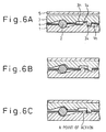
- the third embodiment shown in Figs. 6A to 6C is substantially identical to the first embodiment except that recesses 1h, 3h are provided in the piston 1 and the pressure plate 3, respectively, and a projection 1i, 3i are also provided in the piston 1 and the pressure plate 3. A description of the operation is not given because it is the same as the first embodiment.
- the third embodiment has an advantage in that, since the depth of the respective recess can be smaller, the thickness of the recess-carrying member can be reduced.
- the fourth embodiment shown in Figs. 7A to 7C has projections 1j, 3j on a non-slanted wall of the cam surface of the piston 1 and on a non-slanted wall of the cam surface of the pressure plate 3, respectively, for preventing the roller 2 from riding thereon.
- the projections 1j, 3j are designed to be sufficiently higher than the center of the roller so that the roller 2 does not ride on the piston 1 and the pressure plate 3 when the relative rotation occurs in the direction wherein the cam mechanism is inoperative.
- Figs. 8A to 8E show the fifth embodiment wherein Fig. 8D illustrates the relationship between the roller 2 and the piston 1 as seen from the pressure plate 3, and Fig. 8E illustrates the relationship between the roller 2 and the piston 1 as seen from the piston 1.
- the roller 2 is not uniform in diameter in the widthwise direction but is divided into a central larger diameter section 2a and a smaller diameter section 2b at each end.
- a narrow cam surface 1a' wherein recesses 1k and projections 1m are provided in the side portions of the piston 1
- a narrow cam surface 3a' wherein recesses 3k and projections 3m are provided in the side portions of the pressure plate 3, whereby the larger diameter section 2a can be solely in contact with the cam surface.
- the projections 1m, 3m are designed to be higher than the center of the roller 2 so that the smaller diameter sections 2b of the roller 2 abut onto the projection 1m on the piston 1 and the projection 3m on the pressure plate 3 to inhibit the piston 1 and the pressure plate 3 from moving to the left and right in the figure and to prevent the roller 2 from riding on the cam.
- a recess In similar to that of the first embodiment is provided at a location further to the left from the cam surface 1a of the piston 1 and a projection 1p similar to that of the second embodiment is provided at a location further to the right from the cam surface 1a of the piston 1.
- a recess 3n similar to that of the first embodiment is provided at a location further to the right from the cam surface 3a of the pressure plate 3 and a projection 3p similar to that of the second embodiment is provided at a location further to the left from the cam surface 3a of the pressure plate 3.
- the piston 1 and the pressure plate 3 solely have recesses 1r, 3r, respectively, and a pair of fingers 4c are provided on the roller cage 4 by bending upright parts thereof.
- this embodiment is advantageous, compared to the sixth embodiment, in that the manufacturing cost is reduced.
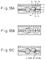
- the piston 1 and the pressure plate 3 have recesses 1t, 3t, respectively, contiguous to the cam surfaces, while the roller cage 4 has a pair of fingers 4d formed by bending the roller cage upright at locations adjacent to the roller 2.
- this embodiment can be easily manufactured. Also, since elements are more collectively located in the vicinity of the roller 2 in comparison with the seventh embodiment, it is possible to dispose the device in a narrower space.
- the piston 1 and the pressure plate 3 have recesses 1v, 3v, respectively, at locations further to the right from the roller.
- the roller cage 4 has a pair of fingers 4e provided at a single location while being projected toward the piston 1 and the pressure plate 3, respectively, which are capable of abutting to the inner side walls 1w, 3w of the recesses 1v, 3v, respectively, when the relative rotation occurs in the direction wherein the cam mechanism is inoperative.
- this embodiment is advantageous in that the machining of the roller cage 4 becomes easier, in comparison with the eighth embodiment.
- a clutch device with a cam mechanism is provided, which is free from drag loss when the phase is switched from a state wherein the cam mechanism is operative to a state wherein it is inoperative.
- a cam groove 1c and a recess 1d are formed on the inner surface 1a of a piston, and a cam groove 3c and a projection 3d to be inserted into the recess 1d are formed on the inner surface 3a of a pressure plate 3.
- a cam roller 2 loosely retained by a roller cage 4.
Landscapes
- Engineering & Computer Science (AREA)
- General Engineering & Computer Science (AREA)
- Mechanical Engineering (AREA)
- Mechanical Operated Clutches (AREA)
- Hydraulic Clutches, Magnetic Clutches, Fluid Clutches, And Fluid Joints (AREA)
- Transmission Devices (AREA)
Applications Claiming Priority (3)
| Application Number | Priority Date | Filing Date | Title |
|---|---|---|---|
| JP32540/95 | 1995-02-21 | ||
| JP07032540A JP3104561B2 (ja) | 1995-02-21 | 1995-02-21 | クラッチ装置 |
| JP3254095 | 1995-02-21 |
Publications (2)
| Publication Number | Publication Date |
|---|---|
| EP0728958A1 true EP0728958A1 (de) | 1996-08-28 |
| EP0728958B1 EP0728958B1 (de) | 2000-11-15 |
Family
ID=12361777
Family Applications (1)
| Application Number | Title | Priority Date | Filing Date |
|---|---|---|---|
| EP96102487A Expired - Lifetime EP0728958B1 (de) | 1995-02-21 | 1996-02-19 | Kupplungseinrichtung |
Country Status (5)
| Country | Link |
|---|---|
| US (1) | US5701983A (de) |
| EP (1) | EP0728958B1 (de) |
| JP (1) | JP3104561B2 (de) |
| KR (1) | KR0182816B1 (de) |
| DE (1) | DE69610936T2 (de) |
Cited By (3)
| Publication number | Priority date | Publication date | Assignee | Title |
|---|---|---|---|---|
| EP0943401A1 (de) * | 1998-03-19 | 1999-09-22 | Etablissements Charles Maire | Pneumatischer Schrauber |
| WO2011050775A1 (de) * | 2009-10-29 | 2011-05-05 | Schaeffler Technologies Gmbh & Co. Kg | Nasskupplung |
| WO2014182515A1 (en) * | 2013-05-10 | 2014-11-13 | Borgwarner Inc. | Clutch apparatus with lockable actuating device |
Families Citing this family (4)
| Publication number | Priority date | Publication date | Assignee | Title |
|---|---|---|---|---|
| US6068572A (en) * | 1999-03-31 | 2000-05-30 | Daimlerchrysler Corporation | Method for reacting thrust loading in an automatic transmission |
| JP3726685B2 (ja) * | 2001-01-15 | 2005-12-14 | 日産自動車株式会社 | クラッチ装置 |
| KR100461434B1 (ko) * | 2002-11-11 | 2004-12-10 | 현대자동차주식회사 | 자동변속기의 피스톤 장치 |
| JP2017155857A (ja) * | 2016-03-02 | 2017-09-07 | Ntn株式会社 | 逆入力遮断装置 |
Citations (7)
| Publication number | Priority date | Publication date | Assignee | Title |
|---|---|---|---|---|
| US2057742A (en) * | 1935-01-16 | 1936-10-20 | Robert C Russell | Clutch structure |
| US3199374A (en) * | 1961-04-12 | 1965-08-10 | Gen Motors Corp | Drive sustaining device |
| FR2078382A5 (de) * | 1970-02-16 | 1971-11-05 | Hurth Masch Zahnrad Carl | |
| DE2540489B1 (de) * | 1975-09-11 | 1976-12-09 | Walterscheid Gmbh Jean | Drehmomentbegrenzungskupplung mit Freigang |
| GB2060339A (en) * | 1978-01-31 | 1981-05-07 | Lely Nv C Van Der | Overload clutches |
| EP0478917A1 (de) * | 1990-10-05 | 1992-04-08 | DEUTSCHE PERROT-BREMSE GmbH | Automatische Nachstelleinrichtung für eine mechanisch betätigte Gleitsattel-Scheibenbremse |
| DE4038731A1 (de) * | 1990-12-05 | 1992-06-11 | Man Nutzfahrzeuge Ag | Kupplungseinrichtung zum verbinden zweier mit unterschiedlicher drehzahl rotierender wellen |
Family Cites Families (20)
| Publication number | Priority date | Publication date | Assignee | Title |
|---|---|---|---|---|
| US1974390A (en) * | 1932-07-08 | 1934-09-18 | Clarence M Eason | Servo clutch |
| US2887200A (en) * | 1950-02-11 | 1959-05-19 | Curtiss Wright Corp | Servo-operated clutches |
| US2827994A (en) * | 1954-10-18 | 1958-03-25 | Curtiss Wright Corp | Follow-up clutches |
| US3000479A (en) * | 1958-06-23 | 1961-09-19 | Roper Hydraulics Inc | Electromagnetic clutch |
| US3360087A (en) * | 1966-06-06 | 1967-12-26 | Twin Disc Inc | Hydraulically actuated friction clutch having torque control means |
| US3404585A (en) * | 1966-06-13 | 1968-10-08 | Eaton Yale & Towne | Drive mechanism |
| DE1915651A1 (de) * | 1969-03-27 | 1970-10-08 | Klaue Hermann | Vollbelag-Scheibenbremse ohne Reibungsselbstverstaerkung |
| US3733920A (en) * | 1971-08-16 | 1973-05-22 | Gen Motors Corp | Transmission and hydraulic source |
| US3688882A (en) * | 1971-08-16 | 1972-09-05 | Gen Motors Corp | Fluid operated clutch with one way engager |
| US3717229A (en) * | 1971-08-16 | 1973-02-20 | Gen Motors Corp | Fluid clutch with one way torque limiting engager |
| JP2581965B2 (ja) * | 1988-08-30 | 1997-02-19 | 株式会社エフ・シー・シー | 動力伝達装置 |
| JPH0269134A (ja) * | 1988-09-02 | 1990-03-08 | Seiwa Kasei Kk | 数の子褐変防止剤 |
| JP2536144B2 (ja) * | 1989-04-07 | 1996-09-18 | トヨタ自動車株式会社 | 動力伝達機構 |
| JP2540947B2 (ja) * | 1989-07-17 | 1996-10-09 | トヨタ自動車株式会社 | 動力伝達装置 |
| US5031746A (en) * | 1990-03-30 | 1991-07-16 | Erkki Koivunen | Multi-mode clutch for change-speed transmissions |
| GB2251465A (en) * | 1990-10-31 | 1992-07-08 | Massey Ferguson Mfg | A mechanical clutch |
| US5106348A (en) * | 1991-05-08 | 1992-04-21 | Koivunen Erkki A | Bi-directional multi-mode clutch for change-speed transmission unit for automatic change speed transmissions |
| CA2116411C (en) * | 1993-02-26 | 1997-08-26 | Jun Aoki | Connecting system |
| JP3104519B2 (ja) * | 1994-03-18 | 2000-10-30 | トヨタ自動車株式会社 | クラッチ装置 |
| JP3104524B2 (ja) * | 1994-04-07 | 2000-10-30 | トヨタ自動車株式会社 | 自動変速機のクラッチ装置 |
-
1995
- 1995-02-21 JP JP07032540A patent/JP3104561B2/ja not_active Expired - Fee Related
-
1996
- 1996-02-12 US US08/600,027 patent/US5701983A/en not_active Expired - Fee Related
- 1996-02-19 DE DE69610936T patent/DE69610936T2/de not_active Expired - Fee Related
- 1996-02-19 EP EP96102487A patent/EP0728958B1/de not_active Expired - Lifetime
- 1996-02-21 KR KR1019960004017A patent/KR0182816B1/ko not_active Expired - Fee Related
Patent Citations (7)
| Publication number | Priority date | Publication date | Assignee | Title |
|---|---|---|---|---|
| US2057742A (en) * | 1935-01-16 | 1936-10-20 | Robert C Russell | Clutch structure |
| US3199374A (en) * | 1961-04-12 | 1965-08-10 | Gen Motors Corp | Drive sustaining device |
| FR2078382A5 (de) * | 1970-02-16 | 1971-11-05 | Hurth Masch Zahnrad Carl | |
| DE2540489B1 (de) * | 1975-09-11 | 1976-12-09 | Walterscheid Gmbh Jean | Drehmomentbegrenzungskupplung mit Freigang |
| GB2060339A (en) * | 1978-01-31 | 1981-05-07 | Lely Nv C Van Der | Overload clutches |
| EP0478917A1 (de) * | 1990-10-05 | 1992-04-08 | DEUTSCHE PERROT-BREMSE GmbH | Automatische Nachstelleinrichtung für eine mechanisch betätigte Gleitsattel-Scheibenbremse |
| DE4038731A1 (de) * | 1990-12-05 | 1992-06-11 | Man Nutzfahrzeuge Ag | Kupplungseinrichtung zum verbinden zweier mit unterschiedlicher drehzahl rotierender wellen |
Cited By (7)
| Publication number | Priority date | Publication date | Assignee | Title |
|---|---|---|---|---|
| EP0943401A1 (de) * | 1998-03-19 | 1999-09-22 | Etablissements Charles Maire | Pneumatischer Schrauber |
| FR2776220A1 (fr) * | 1998-03-19 | 1999-09-24 | Maire Charles Ets | Visseuse pneumatique |
| US6085849A (en) * | 1998-03-19 | 2000-07-11 | Ets Charles Maire | Pneumatic screwdriver |
| WO2011050775A1 (de) * | 2009-10-29 | 2011-05-05 | Schaeffler Technologies Gmbh & Co. Kg | Nasskupplung |
| US8464852B2 (en) | 2009-10-29 | 2013-06-18 | Schaeffler Technologies AG & Co. KG | Wet clutch |
| WO2014182515A1 (en) * | 2013-05-10 | 2014-11-13 | Borgwarner Inc. | Clutch apparatus with lockable actuating device |
| US9790999B2 (en) | 2013-05-10 | 2017-10-17 | Borgwarner Inc. | Clutch apparatus with lockable actuating device |
Also Published As
| Publication number | Publication date |
|---|---|
| EP0728958B1 (de) | 2000-11-15 |
| US5701983A (en) | 1997-12-30 |
| KR960031832A (ko) | 1996-09-17 |
| KR0182816B1 (ko) | 1999-04-01 |
| DE69610936D1 (de) | 2000-12-21 |
| DE69610936T2 (de) | 2001-03-29 |
| JPH08226457A (ja) | 1996-09-03 |
| JP3104561B2 (ja) | 2000-10-30 |
Similar Documents
| Publication | Publication Date | Title |
|---|---|---|
| EP0640773A1 (de) | Reibungs - Verbindungs - Vorrichtung für eine selbsttätige Übertragung | |
| US5701983A (en) | Clutch device | |
| EP3739231B1 (de) | Leistungsübertragungsvorrichtung | |
| US5913397A (en) | Clutch structure with piston having surface recessed from pressure surface for reducing stress concentration | |
| JP2003013996A (ja) | 摩擦係合装置 | |
| US20250334155A1 (en) | Clutch device | |
| JP3328311B2 (ja) | 多板クラッチ | |
| JP2581965B2 (ja) | 動力伝達装置 | |
| JPH0989005A (ja) | クラッチドラムの構造およびその製造方法 | |
| US6000293A (en) | Multi-clutched transmission | |
| EP4310352B1 (de) | Kupplungsvorrichtung | |
| KR20210045286A (ko) | 신규한 구조의 회전축 어셈블리 | |
| JP5001538B2 (ja) | 動力分配装置 | |
| JP3168906B2 (ja) | クラッチ装置 | |
| JP3655955B2 (ja) | 自動車用トランスファ装置 | |
| JP4286353B2 (ja) | 摩擦係合装置 | |
| JP2007327592A (ja) | 産業車両のトランスミッション装置 | |
| JP3581438B2 (ja) | 自動変速機の締結要素 | |
| JP4668382B2 (ja) | 多板式摩擦係合装置 | |
| JP2586018B2 (ja) | 無段変速装置 | |
| JPS6212115Y2 (de) | ||
| JP2890460B2 (ja) | 自動変速機用歯車変速装置 | |
| EP0387707B1 (de) | Antriebsübertragung | |
| JP3701774B2 (ja) | 無段変速機 | |
| JPH10159871A (ja) | 締結要素及び自動変速機 |
Legal Events
| Date | Code | Title | Description |
|---|---|---|---|
| PUAI | Public reference made under article 153(3) epc to a published international application that has entered the european phase |
Free format text: ORIGINAL CODE: 0009012 |
|
| 17P | Request for examination filed |
Effective date: 19960219 |
|
| AK | Designated contracting states |
Kind code of ref document: A1 Designated state(s): DE FR GB |
|
| 17Q | First examination report despatched |
Effective date: 19961230 |
|
| GRAG | Despatch of communication of intention to grant |
Free format text: ORIGINAL CODE: EPIDOS AGRA |
|
| 17Q | First examination report despatched |
Effective date: 19961230 |
|
| GRAG | Despatch of communication of intention to grant |
Free format text: ORIGINAL CODE: EPIDOS AGRA |
|
| GRAH | Despatch of communication of intention to grant a patent |
Free format text: ORIGINAL CODE: EPIDOS IGRA |
|
| GRAH | Despatch of communication of intention to grant a patent |
Free format text: ORIGINAL CODE: EPIDOS IGRA |
|
| GRAA | (expected) grant |
Free format text: ORIGINAL CODE: 0009210 |
|
| AK | Designated contracting states |
Kind code of ref document: B1 Designated state(s): DE FR GB |
|
| ET | Fr: translation filed | ||
| REF | Corresponds to: |
Ref document number: 69610936 Country of ref document: DE Date of ref document: 20001221 |
|
| PLBE | No opposition filed within time limit |
Free format text: ORIGINAL CODE: 0009261 |
|
| STAA | Information on the status of an ep patent application or granted ep patent |
Free format text: STATUS: NO OPPOSITION FILED WITHIN TIME LIMIT |
|
| 26N | No opposition filed | ||
| REG | Reference to a national code |
Ref country code: GB Ref legal event code: IF02 |
|
| REG | Reference to a national code |
Ref country code: GB Ref legal event code: 746 Effective date: 20041018 |
|
| REG | Reference to a national code |
Ref country code: FR Ref legal event code: D6 |
|
| PGFP | Annual fee paid to national office [announced via postgrant information from national office to epo] |
Ref country code: GB Payment date: 20060215 Year of fee payment: 11 |
|
| PGFP | Annual fee paid to national office [announced via postgrant information from national office to epo] |
Ref country code: DE Payment date: 20060216 Year of fee payment: 11 |
|
| PGFP | Annual fee paid to national office [announced via postgrant information from national office to epo] |
Ref country code: FR Payment date: 20060220 Year of fee payment: 11 |
|
| GBPC | Gb: european patent ceased through non-payment of renewal fee |
Effective date: 20070219 |
|
| REG | Reference to a national code |
Ref country code: FR Ref legal event code: ST Effective date: 20071030 |
|
| PG25 | Lapsed in a contracting state [announced via postgrant information from national office to epo] |
Ref country code: DE Free format text: LAPSE BECAUSE OF NON-PAYMENT OF DUE FEES Effective date: 20070901 |
|
| PG25 | Lapsed in a contracting state [announced via postgrant information from national office to epo] |
Ref country code: GB Free format text: LAPSE BECAUSE OF NON-PAYMENT OF DUE FEES Effective date: 20070219 Ref country code: FR Free format text: LAPSE BECAUSE OF NON-PAYMENT OF DUE FEES Effective date: 20070228 |