EP0725021B1 - Véhicule avec un mécanisme de préhension pour le vidage de bacs à ordures - Google Patents
Véhicule avec un mécanisme de préhension pour le vidage de bacs à ordures Download PDFInfo
- Publication number
- EP0725021B1 EP0725021B1 EP96104252A EP96104252A EP0725021B1 EP 0725021 B1 EP0725021 B1 EP 0725021B1 EP 96104252 A EP96104252 A EP 96104252A EP 96104252 A EP96104252 A EP 96104252A EP 0725021 B1 EP0725021 B1 EP 0725021B1
- Authority
- EP
- European Patent Office
- Prior art keywords
- vehicle
- collecting container
- vehicle according
- container
- cab
- Prior art date
- Legal status (The legal status is an assumption and is not a legal conclusion. Google has not performed a legal analysis and makes no representation as to the accuracy of the status listed.)
- Expired - Lifetime
Links
- 239000002699 waste material Substances 0.000 claims description 26
- 230000033001 locomotion Effects 0.000 claims description 21
- 230000001681 protective effect Effects 0.000 claims description 15
- 238000007789 sealing Methods 0.000 claims description 7
- 238000010276 construction Methods 0.000 claims description 5
- 230000008878 coupling Effects 0.000 claims description 5
- 238000010168 coupling process Methods 0.000 claims description 5
- 238000005859 coupling reaction Methods 0.000 claims description 5
- 238000003032 molecular docking Methods 0.000 claims description 3
- 238000000151 deposition Methods 0.000 claims 1
- 101100494448 Caenorhabditis elegans cab-1 gene Proteins 0.000 description 8
- 230000008901 benefit Effects 0.000 description 7
- 238000000034 method Methods 0.000 description 6
- 230000008569 process Effects 0.000 description 6
- 239000000565 sealant Substances 0.000 description 6
- 239000000945 filler Substances 0.000 description 5
- 238000006073 displacement reaction Methods 0.000 description 2
- 238000004804 winding Methods 0.000 description 2
- 229910000831 Steel Inorganic materials 0.000 description 1
- 206010053648 Vascular occlusion Diseases 0.000 description 1
- 230000009471 action Effects 0.000 description 1
- 230000005540 biological transmission Effects 0.000 description 1
- 230000015572 biosynthetic process Effects 0.000 description 1
- 239000000969 carrier Substances 0.000 description 1
- 230000008859 change Effects 0.000 description 1
- 238000004140 cleaning Methods 0.000 description 1
- 239000000428 dust Substances 0.000 description 1
- 238000009434 installation Methods 0.000 description 1
- 238000002372 labelling Methods 0.000 description 1
- 239000007788 liquid Substances 0.000 description 1
- 239000010813 municipal solid waste Substances 0.000 description 1
- 239000010893 paper waste Substances 0.000 description 1
- 238000005192 partition Methods 0.000 description 1
- 230000008439 repair process Effects 0.000 description 1
- 239000010959 steel Substances 0.000 description 1
Images


Classifications
-
- B—PERFORMING OPERATIONS; TRANSPORTING
- B65—CONVEYING; PACKING; STORING; HANDLING THIN OR FILAMENTARY MATERIAL
- B65F—GATHERING OR REMOVAL OF DOMESTIC OR LIKE REFUSE
- B65F3/00—Vehicles particularly adapted for collecting refuse
- B65F3/02—Vehicles particularly adapted for collecting refuse with means for discharging refuse receptacles thereinto
- B65F3/04—Linkages, pivoted arms, or pivoted carriers for raising and subsequently tipping receptacles
- B65F3/041—Pivoted arms or pivoted carriers
- B65F3/043—Pivoted arms or pivoted carriers with additional means for keeping the receptacle substantially vertical during raising
-
- B—PERFORMING OPERATIONS; TRANSPORTING
- B65—CONVEYING; PACKING; STORING; HANDLING THIN OR FILAMENTARY MATERIAL
- B65F—GATHERING OR REMOVAL OF DOMESTIC OR LIKE REFUSE
- B65F3/00—Vehicles particularly adapted for collecting refuse
- B65F3/02—Vehicles particularly adapted for collecting refuse with means for discharging refuse receptacles thereinto
- B65F3/04—Linkages, pivoted arms, or pivoted carriers for raising and subsequently tipping receptacles
- B65F3/041—Pivoted arms or pivoted carriers
- B65F3/046—Pivoted arms or pivoted carriers with additional means for assisting the tipping of the receptacle after or during raising
-
- B—PERFORMING OPERATIONS; TRANSPORTING
- B65—CONVEYING; PACKING; STORING; HANDLING THIN OR FILAMENTARY MATERIAL
- B65F—GATHERING OR REMOVAL OF DOMESTIC OR LIKE REFUSE
- B65F3/00—Vehicles particularly adapted for collecting refuse
- B65F3/14—Vehicles particularly adapted for collecting refuse with devices for charging, distributing or compressing refuse in the interior of the tank of a refuse vehicle
- B65F3/20—Vehicles particularly adapted for collecting refuse with devices for charging, distributing or compressing refuse in the interior of the tank of a refuse vehicle with charging pistons, plates, or the like
- B65F3/201—Vehicles particularly adapted for collecting refuse with devices for charging, distributing or compressing refuse in the interior of the tank of a refuse vehicle with charging pistons, plates, or the like the charging pistons, plates or the like moving rectilinearly
-
- B—PERFORMING OPERATIONS; TRANSPORTING
- B65—CONVEYING; PACKING; STORING; HANDLING THIN OR FILAMENTARY MATERIAL
- B65F—GATHERING OR REMOVAL OF DOMESTIC OR LIKE REFUSE
- B65F3/00—Vehicles particularly adapted for collecting refuse
- B65F2003/006—Constructional features relating to the tank of the refuse vehicle
- B65F2003/008—Constructional features relating to the tank of the refuse vehicle interchangeable
-
- B—PERFORMING OPERATIONS; TRANSPORTING
- B65—CONVEYING; PACKING; STORING; HANDLING THIN OR FILAMENTARY MATERIAL
- B65F—GATHERING OR REMOVAL OF DOMESTIC OR LIKE REFUSE
- B65F3/00—Vehicles particularly adapted for collecting refuse
- B65F3/02—Vehicles particularly adapted for collecting refuse with means for discharging refuse receptacles thereinto
- B65F2003/0263—Constructional features relating to discharging means
- B65F2003/0273—Constructional features relating to discharging means capable of rotating around a vertical axis
-
- B—PERFORMING OPERATIONS; TRANSPORTING
- B65—CONVEYING; PACKING; STORING; HANDLING THIN OR FILAMENTARY MATERIAL
- B65F—GATHERING OR REMOVAL OF DOMESTIC OR LIKE REFUSE
- B65F3/00—Vehicles particularly adapted for collecting refuse
- B65F3/02—Vehicles particularly adapted for collecting refuse with means for discharging refuse receptacles thereinto
- B65F2003/0263—Constructional features relating to discharging means
- B65F2003/0279—Constructional features relating to discharging means the discharging means mounted at the front of the vehicle
Definitions
- the invention relates to a vehicle for transportation of waste materials according to the preamble of the claim 1 and as known from EP-A-235 784.
- EP-A-0 235 784, EP-A-0 163 859 and US-A-3 841 508 are vehicles with a cradle known for waste bins, where instead of one directly fillable container behind the cab with one Press interacting hopper is arranged, whose ejection opening is movable with the filling opening connectable to the vehicle connected container is. Pressed into the collection container via the press Waste has springback properties. Becomes now the collection container moves, be it to the complete one Stopping or swiveling up to tip over, the springback then turns part of the waste materials into waste pressed out of the filling opening of the collecting container, which then fall on the vehicle frame and on the floor, so that additional cleaning work is required.
- the invention is based on the object of a vehicle of the generic type so that a "cleaner" Operation is guaranteed.
- This task is accomplished with the means of the labeling part of claim 1 solved.
- This arrangement offers the possibility the collection container both empty and completely filled closed to transport.
- the empty storage container is picked up from behind by the vehicle, or the vehicle drives under those on legs Collection container so that the filling opening to the discharge opening is docked while sealing. This ensures that when inserting the Do not waste anything from the press into the collection container can kick outside.
- the filled collecting container is in reversed from the vehicle.
- This is arranged on the vehicle a moving device with is connected to a drive and via which the collecting container when picking up and putting down at least part of the Way to dock onto the sealant essentially is horizontally movable.
- Such a movement device has the advantage that the collection container at least targeted for the part of the pick-up and drop-off movement is performed with respect to the sealant and thus a defined system with one independent of the vehicle movement limitable movement is guaranteed.
- the movement device can Invention by one on the vehicle in the longitudinal direction Slidable slides are formed with the vertical Aligned pin is provided in corresponding Can engage recesses in the collection container, so that the collecting container via lifting devices or the like put the vehicle on and then dock it in his final position is moved.
- This system is special also suitable for cases in which the to be recorded and the container to be set down are on legs, so that they go under from the vehicle and then over appropriate in - vehicle equipment for changing the Vehicle height can be picked up or set down.
- this movement device can the invention on a pivotable and / or longitudinally displaceable gate-like angle arm arranged on the vehicle with hooks that encompass the filling opening.
- the particular advantage of the hook lift is that that the collection container with appropriate locking can also be emptied at the rear end by tipping.
- the recording process is designed so that when Pick up the last part and when setting down the first part of the movement path by a shift in the longitudinal direction of the vehicle takes place so that a perfect docking or Loosen the filling opening of the container at the discharge opening of the hopper is guaranteed.
- the discharge opening of the hopper on the vehicle assigned a functional device provided with a drive is, which has driver means that with a corresponding rest of a vertically guided on the collection container Locking door for the fill opening are connectable.
- the particular advantage of this arrangement is that no drive devices on the collection container itself are required, but connected to the vehicle are and driven by the vehicle's power supply are.
- the drive can, for example, by a piston-cylinder unit connected to the driver or also by means of a circulation chain connected to the driver are formed, which can be driven by a hydraulic motor is.
- the functional device with the movement device connected is.
- the extension opening has a tubular extension, through the in the lower area of the bulkhead of the collection container arranged filling opening into the collecting container reaches in, and that sealing means are provided, which extend over at least part of the circumference of the tubular Extension.
- a channel-like protective cover in the interior of the collecting container, especially if this provided with a preferably pivotable locking plate is how they come in different configurations in the Claims 8 to 11 is specified, can be a flawless Reach the release container from the vehicle, without anything falling out of the container.
- the collecting container is pulled off a piece from the press, but only to the extent that the tubular extension is still in the filler opening with its free end.
- the locking plate is swiveled in. This can from above, from below, or through two door wings like the Partial locking plates arranged on the side walls of the protective cover respectively.
- the pivoting in the closing direction in the same direction as the filling stroke of the press, it can can be used for actuation so that on the collection container only appropriate locking means for the locking plate are to be provided, which should also be operable from the outside.
- the locking plate can also be used with the front surface of the ram on the one hand and with the channel-like protective cover on the other hand, be designed to be releasably connectable. While the locking plate remains with the press ram connected. When the filling is complete, the locking plate retracted into the channel-like protective cover, locked there and at the same time released from the ram and this moved back again. The lock door can then also getting closed.
- locking means on the carrier arranged for fixed coupling of the collecting container are.
- Such locking means for example formed by pins and / or hooks arranged on the carrier can be made in corresponding recesses in the front area of the collecting container is reached, that the carrier on the one hand and the collection container on the other form an essentially rigid unit, so that practically no, at least no disturbing relative movements between the collection container and the one connected to it Discharge opening of the hopper occur can and thus a perfect installation of the sealant is guaranteed.
- the locking means are expedient with actuating means, for example in Form of hydraulic cylinders or the like. Provided. Further takes the coupled collection container by its weight a part of the tilting moment in the area of the articulated fastening point on what relieves the load on the vehicle chassis leads in this area.
- the carrier is designed as a box structure is, the hopper and the side walls Are part of the load-bearing structure.
- This arrangement has the advantage that a rigid Construction is created that both the load when operating the swivel arm pair as well as the load is able to record when the press is pressed.
- hopper ends up in side walls, which are essentially across the cab extend to the front area.
- a crossbar for support, guidance and locking of the collecting container which is arranged around a pivoting axis extending in the longitudinal direction of the vehicle is mounted, preferably the pivot axis with the Joint axis of the third attachment point of the carrier flees.
- the collection container is also in one Three-point support connected to the vehicle chassis, the two front support points through the fixed Support points of the carrier formed on the vehicle chassis during the third point of support through the Swivel bearing of the crossbar is formed. That is the crossbar supporting joint can also be done by a Ball joint are formed.
- At least one between crossbar and Effective positioning spring element provided in the vehicle chassis is. This ensures that in the unloaded state the crossbar with guide rollers and / or locking elements is provided for the collection container, in is aligned horizontally with respect to the vehicle chassis, so that when picking up or driving under the collecting container its bottom rails engage precisely in the guide rollers can.
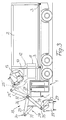
- the vehicle shown in Fig. 1 for picking up and transporting of waste is with a lowered Cab 1 provided so that above the cab greater free space is available.
- a collecting container 2 is arranged releasably, via Pin or fasteners 3 is attached.
- the collection container 2 can here after loosening the closures 3 in different Be removed from the vehicle. This can either in that the collection container 2 down has extendable supports shown in more detail in FIG. 8, so that the vehicle comes with a lowering device is equipped after lowering from the elevated Can drive away the container. The recording then takes place in reverse order, as is shown in FIGS. 8 to 11 will be explained.
- hook lift through which a recorded Collect the container a short distance is moved horizontally at the rear and then by swiveling of the lift hook is pushed further back so that the vehicle as soon as the collecting container with its rear edge touches the ground, with further swiveling of the Can lift lift hook forward and the collection container can settle on the floor. Picking up an empty one Collecting container is done in the same way.
- hook lift constructions are known and need here in their Structure not to be explained in more detail.
- the one carrying the hook However, arm must be gate-shaped, so that he Grips the discharge opening of the hopper.
- Another option is to use the vehicle to provide a so-called tipping bridge, which with a Cable winch is equipped so that after releasing the lock and again moving the collection container in a horizontal direction backwards, the tipping bridge swung up and the collecting container with the help of the winch can be lowered over the inclined tipping bridge, until again the rear edge of the collecting container the bottom touched and drive the vehicle forward while lowering further can until the collection container is finally on the floor lies on. The recording is done in reverse Wise.
- a tipper bridge allows it if instead a hydraulic lifting device is provided for a cable winch is, the collection container on its rear face upright instead of him on his To settle floor area. All that is required is when swiveling up and simultaneously lowering the collecting container to swivel the tipping bridge into the 90 ° position, as soon as the collecting container with its lower rear edge gets up on the floor. The vehicle then drives accordingly backwards. The recording takes place in reverse Sequence.
- the rear end wall 4 of the collecting container 2 is more common Formed as a lockable flap, so that after Open the lock of the contents of the collection container by Tipping can be emptied.
- the collection container can also be designed so that the front end wall 5 as Emptying flap is designed and completely for emptying can be folded up.
- the press On the vehicle itself is in the space between the cab 1 and the end wall 5 of the collecting container 2 a press arranged, the hydraulic press cylinder 8 and one Press ram 9, dashed here in the press position is shown.
- the press also has a hopper 10 on, the discharge opening through a tubular Extension 11 is formed, which is dimensioned so that it through the filling opening 6 of the collecting container 2 into this protrudes. Now 9 waste with retracted ram thrown into the hopper 10, this can over the press ram 9 through the tubular extension 11 of the discharge opening of the hopper 10 in the Collection container 2 are inserted.
- the tubular extension is, as will be explained below, in Collection container encompassing the edge of the filling opening assigned channel-like protective cover 66 into which the Extension 11 is introduced.
- the Swinging flap extending the width of the filling opening 12 may be arranged, which is dimensioned so that when inserted Extension 11 rests on this. Now the container 2 is withdrawn, then the flap pivots 12 down and covers the upper area of the filler opening 6 and secures them against falling out of the container contents, until the door 7 is closed.
- the hopper 10 runs upwards in side walls 13, which are essentially beyond the driver's cab 1 extend into the front area.
- Fig. 1 is for Not simplifying the illustration of the front side wall shown.
- the upper edges 14 of both side walls are with a guide for a displaceable and preferably windable Cover 15 provided so that the space above the Driver's cab and the press in the driving mode completely can be locked.
- Via a shift drive 16 For example, a winding device, then this space can be opened by pulling back the cover 15.
- the end 17 of guides 14 adjacent winding device 16 is expediently designed so that it at withdrawn cover as shown in dashed lines, can be swung up.
- the vehicle described with reference to FIG. 1 is now for the Change the collecting container 2 so that the Collection container 2 with extendable downwards, not here Supports shown is provided, the vehicle even to release the container after opening the closures 3 can be lowered by a small amount and thus below can drive out of the container.
- the vehicle has one with a hydraulic cylinder provided as a drive carriage 18 on the the vehicle with a displacement of about 50 to 100 cm is slidably mounted, as shown in FIG. 2.
- the sled 18 carries the front closure designed as a driver 3.
- the carriage 18 is now in its rear Position, then the vehicle can take one raised collecting container 2 in the lowered state drive under these until the front locking element on Collection container 2 approximately over the closure 3 of the carriage 18 lies. Then the vehicle is raised so that the lock 3 engages in the closure element on the collecting container 2 and the shutter 3 closed. Now the Carriage 18 moved forward so that when open Door 7, the tubular extension 11 into the fill opening 6 can retract. This process is in progress 8 to 11.
- a functional device 19 is provided in the vehicle, for example in the form of an endless chain or a toothed belt 20, which is provided with a driver 21.
- the Chain 20 is via a drive 22, for example one Hydraulic motor, drivable.
- the trained as a sliding door Door 7 of the filling opening 6 now has a corresponding latch on, in which the driver 21 can engage, so that when Advance over the carriage 18 of the driver 21 initially engages in the catch of door 7 and via the functional device 19 opened the door by moving it upwards can be.
- the carriage 18 then moves on forward until the extension 11 through the filler opening 6 is inserted and the rear container end with the associated Closure 3 can also be locked.
- the Functional device 19 with the carriage 18 a structural unit represents so that when picking up a collection container in the manner described above, the latching of the door 7 in the driver 21 already intervenes, even if the one with the sled 18 connected closure 3 is locked. The door 7 can then be opened before the collection container 2 through the sled towards the tubular extension 11 the press is moved.
- Can on the functional device also corresponding actuatable and drivable actuators for the actuating and locking means one in Collection container arranged locking plate may be arranged.
- Fig. 3 is now in connection with the above Vehicle a device 23 for picking up and emptying a waste container 24 shown and described. All explained in detail above and for explanation the function of the device 23 unnecessary elements are omitted in Fig. 3 for simplicity of illustration.
- the device 23 is supported by a pair of swivel arms 25 formed, the swivel arms parallel to each other and in one The distance from each other is approximately the width corresponds to the cab 1.
- the pair of swivel arms 25 is with a swivel bearing 26 in the front area above the cab 1 arranged on a carrier 27.
- the pair of swivel arms 25 is provided with a swivel drive which is designed in this way is that the swivel arm over an angle of about 180 ° from the lower recording position shown in the Upper rest position 25 'shown in dashed lines pivoted can be.
- the swivel drive can, for example, by one or more hydraulic piston-cylinder units are formed, with corresponding lever arrangements the required swivel angle can be achieved. this will 4 to 6 are shown in more detail.
- Appropriately is also the design of the swivel drive in the form of a so-called hydraulic swivel motor.
- two telescopically nested, with wide helical teeth Provided shaft-piston elements hydraulically axially postponed. The axial movement is determined by a corresponding internal toothing fixed to the housing, which with the toothing of the Shaft interacts, converted into a rotary motion.
- the pair of swivel arms 25 is now connected to a guide means 28, the one Pick-up and tilting device 29 for the waste container 24 wearing.
- the guide means 28 is designed here that while extending over the cab 1 Swivel path of the waste containers 24 aligned approximately vertically remains and until the pair of swivel arms in the fully extended emptying position swiveled 25 '' has been. In this position, the waste container 24 load-bearing pick-up and tilting device via its own Tilt drive, not shown here, for example a hydraulic piston-cylinder arrangement mounted on the guide means, pivoted into the emptying position shown, so that the container contents into the hopper 10 the press 7 can occur.
- the representation of the device 23 in three different Positions of their swivel path indicate that already when shooting and over the entire swivel path Waste container 24 with its guide means between the Swivel arm pair is pivoted through, so that the necessary Free space practically over the free end 30 of the two swivel arms is limited, i.e. at no time neither by the pair of swivel arms still through the container this area is significantly exceeded.
- the representation in FIG. 3 also shows that that required by the device 23 in operation Free space through the upper edge of the collecting container 2 exceeds the specified height only slightly, so that a Clearance profile of less than 4.3 m can be maintained can.
- Fig. 3 also reveals that shown in dashed lines Rest position 25 'the device 23 overall within of the space predetermined by the side walls 13 above the cab 1 can be pivoted. So that is it is possible, as already described above with reference to FIG. 1, the device 23 for pure driving operation completely covered after closing the cover 15 is.
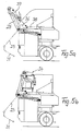
- Fig. 4 is the embodiment explained in Fig. 3 in the basic structure shown on a larger scale and in more detail.
- Matching components have the same reference numerals Mistake.
- 5a, 5b, 6a and 6b then show the sequence of movements of the device 23 to the emptying position for a received waste container 24.
- 6b then shows the driving position.
- Each swivel arm of the swivel arm pair 25 is in the range of A pivotable additional lever 36 is associated with the pivot bearing 26.
- Via a first swivel drive 37 in the form of a hydraulic cylinder is the additional lever 36 with the free end 30 of associated swivel arm connected.
- the additional lever 36 is also each via a second swivel drive 38, the is also designed in the form of a hydraulic cylinder, with the vehicle, preferably with the structure still Carrier 39 for the pivot bearing 26, to be explained in more detail.
- the hydraulic cylinders are only by their lines of action shown dotted. Now becomes the first rotary actuator 37 acted upon, the pair of swivel arms 25 pivots the representation shown in Fig. 5a high.
- the swivel motor eliminates the hydraulic cylinders 37, 38 with the corresponding stop elements.
- the hydraulic swivel motor is immediately axially aligned attached to the pivot bearing 26 on the carrier 39 so that its Shaft attacks directly on the swivel arm 25. Possibly. is it expedient to provide two hydraulic swivel motors that drive one arm of the pair of swivel arms 25.
- Fig. 4 is also schematically the attachment of the Carrier 39 shown on the vehicle. This takes place at the illustrated embodiment by means of a three-point support on the chassis, being immediately behind the cab 1 is a crossbar 42 is arranged, the two side-by-side attachment points firmly to the vehicle chassis connected is. By far behind the crossbar 42, the third attachment point is provided via a centrally located support 43 which is articulated with the Vehicle chassis is connected.
- This pivot point is which cannot be represented here, in the central longitudinal axis of the Vehicle chassis and can both by a single-axis joint as well as be formed by a ball joint. This is it is possible that the vehicle chassis about its longitudinal axis can twist without having to attach the crossbar 42 on the one hand and the hinge point 43 on the other Squeezes can occur.
- the carrier 39 is only shown schematically in FIG. 4.
- the carrier is Box construction, both the hopper 10 and also partial areas of the side walls 13 are designed as load-bearing elements, so that here a relatively low weight with high rigidity results.
- 4 is for the sake of simplicity of illustration the front side wall removed, so that the arrangement of the parts lying between the side walls 13 are visible.
- Fig. 4 also reveals that the carrier designed in this way 39 also for fastening the press cylinder 8 and can be used to guide the ram 9.
- the carrier 39 are preferably below the extension 11 of the discharge opening of the hopper 10 at least two locking pins 44 lying side by side arranged in corresponding recesses in the to be connected Intervene in the collection container and thus the collection container 2 in connection with not shown here lock hook-shaped locking elements practically rigid, so at least in the area where the extension 11 protrudes into the collecting container 2, relative movements between the extension 11 on the one hand and the collecting container 2 are largely excluded.
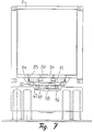
- Fig. 7 is in a view against the rear of the vehicle Support of the collecting container 2 in the area of the rear End of the vehicle chassis 46 shown.
- This is a Crossbar 47 provided for support and locking of the collecting container 2, but also for its guidance during the recording and Serving process.
- the crossbar 47 is with a Pivot bearing 48 provided so that it is in the vehicle longitudinal direction running pivot axis pivotally mounted is. It is preferably aligned by the pivot bearing 48 Defined swivel axis with the articulation axis of the support point 43 of the carrier 39.
- the only rigid connection between this "rigid structure” is hereby fixed with the vehicle chassis 46 connected crossbar 42 am Carrier 39 formed.
- At least one positioning spring element 49 is provided is only shown schematically here. Through the positioning spring element is caused in the unloaded state the crossbar 47 parallel to that through the vehicle chassis 46 level formed remains aligned.
- the positioning spring elements 49 are relatively soft trained so that without any significant force between the crossbar 47 and the vehicle chassis 46 this itself can get over.
- Two guide rollers 50 are provided on the crossbar 47, which can be rotated about vertical axes on the crossbar are stored and the collection container over corresponding Longitudinal trusses on collecting container 2 when picking up and setting down run lengthways.
- Also on the crossbar 47 at the outer ends of each one So-called rotatably mounted about a horizontal axis Bell rollers 52 are provided on which the collection container 2 is supported by the vehicle after recording, so that the rear end of the collecting container 2 on the bell rollers 52 can roll when the collection container 2 over the Carriage 18 is moved into the locking position, as described with reference to FIG. 2.
- container 2 is a for so-called interchangeable platform used vehicle all about hydraulic or pneumatic systems can be lowered.
- the vehicle drives backwards under the collecting container 2, as shown in Fig. 9 is until the end wall of one corresponding stop on the back completely moved carriage 18 comes to the plant.
- how 10 shows the vehicle in its normal position raised so that the container 2 at the front end corresponding pin 3 is connected to the carriage 18, wherein at the same time the driver 21 on the functional device 19 engage in the lock door on the collecting container 2.
- the rear end of the collecting container is supported 2 on the bell rollers 52.
- Fig. 11 shows the vehicle ready for driving and use, wherein the simpler representation because of the device 23 for Picking up and emptying waste containers only by the pivot bearing 26 is indicated.
- the vehicle also allows use in the so-called Bag removal.
- Bag removal is a large-volume receptacle attached to the cradle, in which then the bags be dropped. Short distances can also be used here be put back with a set of swivel arms, because the Driver's view is not blocked. In the same way also the collection of bundled waste paper, in particular Newspapers possible. Even small waste or ash pails can then be emptied into the receptacle by hand, which is only filled to a large extent in the collecting container 2 is emptied.
- a vehicle designed in this way has the further advantage that the collection container 2 is shown a bare steel structure and that on the container 2 itself no drives are arranged. Therefore there are no connection means here to provide for an energy supply. All actuators including their associated power supply connected to the vehicle. This reduces the cost and the Repair susceptibility for the collection container and allowed it also that handling at the landfill, in particular the dumping was carried out with a special landfill vehicle can be. The collection container can thus also without Supervision.
- FIG. 12 schematically shows one possible embodiment for a locking plate 67 is shown with which a closure, preferably an additional closure, the filling opening 6 possible is.
- a closure preferably an additional closure
- the filling opening 6 possible is.
- the lock plate 67 is provided with actuating and / or locking means 68, from the outside of the container, for example via the functional device 19, can be actuated.
- the collection container 2 has been picked up by the vehicle (FIG. 10), when the shutter door is opened the locking plate 67 pivoted up as shown in Fig. 12.
- the collection container 2 is filled, with the ram 9 withdrawn A lock is released via the functional device 19. so that the locking plate 67 folds down.
- the locking plate 67 is then in its end position pressed. Residual waste quantities are here from the channel-like protective cover 66 pushed out into the collecting container.
- the Press ram 9 withdrawn so that the collecting container moves back can be without waste residues closing the door 7 can fall out; this is in Fig. 12 shown in phantom.
- the locking plate 67 can also divided into two and around a vertical axis from each Side walls of the protective cover 66 in the opening cross section be designed to be pivotable. With a corresponding Formation of the locking plate, especially if sufficient Sealing, can also the arrangement of the locking plate for closure the filling opening are sufficient so that on the arrangement the closure door 7 described in FIG. 2 on the collecting container can be dispensed with.
- the protective cover 66 at least with the final length of their floor area with a slightly in slope of the interior of the collecting container is.
- the free space 69 under the protective cover can serve as a collection room for seepage liquid.
- Will the front Front wall 5 also serves as an emptying flap for the collecting container trained, no residues can form in this area accumulate.
- the configurations of the coupling of the Ejection opening of the press with the collecting container to be filled can be used for all vehicles with a Garbage compactor are provided, one of the vehicle detachable collection container is assigned.
Landscapes
- Engineering & Computer Science (AREA)
- Mechanical Engineering (AREA)
- Refuse-Collection Vehicles (AREA)
- Refuse Collection And Transfer (AREA)
- Processing Of Solid Wastes (AREA)
Claims (18)
- Véhicule comprenant un mécanisme de préhension pour le vidage de conteneurs à déchets à saisir et un conteneur collecteur (2) disposé derrière la cabine (1), assemblé de manière amovible avec le véhicule et qui du côté du véhicule dans la partie inférieure de sa paroi frontale présente un orifice de remplissage (6), comprenant un entonnoir déverseur (10), une presse (8, 9) dont l'orifice d'évacuation correspond avec l'orifice de remplissage (6) du conteneur collecteur (2), caractérisé en ce qu'une garniture d'étanchéité opérant en position d'amarrage est prévue entre l'orifice d'évacuation de l'entonnoir déverseur (10) et l'orifice de remplissage (6) et en ce que sur le véhicule (1) est disposé un dispositif de déplacement qui est assemblé avec un entraínement et par l'intermédiaire duquel le conteneur collecteur (2) peut être déplacé sensiblement à l'horizontale au moins sur une partie de la trajectoire sur le véhicule pour l'amarrage à la garniture d'étanchéité (19).
- Véhicule selon la revendication 1, caractérisé en ce que le dispositif de déplacement est constitué par un chariot (18) déplaçable sur le véhicule dans le sens longitudinal et muni de taquets verticaux destinés à s'emboíter dans des encoches sur le conteneur collecteur (2).
- Véhicule selon la revendication 1, caractérisé en ce que le dispositif de déplacement est formé par un bras angulaire pivotant sur le véhicule et muni de crochets et en ce que le bras angulaire est conçu comme un portique et entoure l'orifice de remplissage sur le conteneur collecteur.
- Véhicule selon la revendication 3, caractérisé en ce que le bras angulaire pivotant est monté de façon à pouvoir se déplacer sur le véhicule.
- Véhicule selon l'une des revendications 1 à 4, caractérisé en ce qu'à l'orifice d'évacuation de l'entonnoir déverseur (10) sur le véhicule est disposé un dispositif de fonctionnement (19) muni d'un entraínement (22) qui présente des taquets d'entraínement (21) pouvant être assemblés avec un taquet d'enclenchement correspondant d'une porte de fermeture (7) guidée verticalement sur le conteneur collecteur (2) et destinée à l'orifice de remplissage (6).
- Véhicule selon la revendication 5, caractérisé en ce que le dispositif de fonctionnement est lié au dispositif de déplacement.
- Véhicule selon l'une des revendications 1 à 6, caractérisé en ce que l'orifice d'évacuation présente un prolongement (11) en forme de tube qui passe à travers l'orifice de remplissage (6) disposé dans la zone inférieure de la paroi frontale (5) du conteneur collecteur (2) et arrive jusque dans le conteneur collecteur (2) et en ce que les garnitures d'étanchéité s'étendent au moins sur une partie du pourtour du prolongement (11) en forme de tube.
- Véhicule selon la revendication 7, caractérisé en ce que l'orifice de remplissage (6) est muni d'un couvercle protecteur (66) en forme de canal, disposé dans le conteneur collecteur (2), qui entoure au moins une partie des bords de l'orifice de remplissage (6) et dans lequel le prolongement (11) en forme de tube de la presse (8, 9) peut être introduit.
- Véhicule selon la revendication 8, caractérisé en ce que le couvercle protecteur (66) en forme de canal peut être bloqué par au moins une plaque d'arrêt (67) recouvrant la section transversale, de préférence par une plaque d'arrêt (67) pivotant dans la section de passage.
- Véhicule selon la revendication 9, caractérisé en ce que la plaque d'arrêt (67) est montée en rotation dans la section de passage dans le sens d'avancement de la presse (8, 9).
- Véhicule selon l'une des revendications 9 ou 10, caractérisé en ce que la plaque d'arrêt (67) est reliée à des moyens d'actionnement et/ou de fermeture qui peuvent être actionnés du côté extérieur du conteneur collecteur (2).
- Véhicule selon l'une des revendications 1 à 11, comprenant un support (27) disposé derrière la cabine (1), assemblé avec le châssis du véhicule et destiné au dispositif de préhension, caractérisé en ce que des moyens de verrouillage (44) sont disposés sur le support (27) pour l'amarrage fixe du conteneur collecteur (2).
- Véhicule selon la revendication 12, caractérisé en ce que les moyens d'entraínement (8) de la presse sont montés sur le support (27) et en ce que le piston de compression (9) est guidé.
- Véhicule selon l'une des revendications 12 ou 13, caractérisé en ce que le support (27) est réalisé comme une structure de benne, l'entonnoir déverseur (10) et les parois latérales au moins faisant partie de la structure portante.
- Véhicule selon l'une des revendications 1 à 14, caractérisé en ce que l'entonnoir déverseur (10) débouche vers le haut dans les parois latérales (13) qui s'étendent sensiblement au-delà de la cabine (1) jusque dans la zone frontale.
- Véhicule selon l'une des revendications 12 à 15, caractérisé en ce que le support (27) est fixé sur le châssis du véhicule au moyen d'un appui en trois points - par rapport à l'axe longitudinal du véhicule - deux points de fixation situés l'un à côté de l'autre étant assemblés de manière fixe avec le châssis du véhicule et le troisième point de fixation à distance des deux autres points de fixation étant assemblé de manière articulée avec le châssis de véhicule (46).
- Véhicule selon la revendication 16, caractérisé en ce que dans la zone de l'extrémité arrière du châssis du véhicule (46) est disposée une traverse (47) destinée à soutenir, guider et verrouiller le conteneur collecteur (2) et qui est montée en rotation autour d'un axe pivotant passant dans le sens longitudinal du véhicule, l'axe de pivotement étant aligné avec l'axe d'articulation du troisième point de fixation du support (27).
- Véhicule selon la revendication 17, caractérisé en ce qu'il est prévu au moins un élément élastique (49) de positionnement opérant entre la traverse (47) et le châssis du véhicule (46).
Applications Claiming Priority (5)
| Application Number | Priority Date | Filing Date | Title |
|---|---|---|---|
| DE4204062 | 1992-02-12 | ||
| DE19924204062 DE4204062A1 (de) | 1992-02-12 | 1992-02-12 | Fahrzeug zum aufnehmen und transportieren von abfallstoffen |
| DE9209433U | 1992-07-14 | ||
| DE9209433U DE9209433U1 (de) | 1992-07-14 | 1992-07-14 | Transportfahrzeug für Abfallstoffe |
| EP93917395A EP0579828B1 (fr) | 1992-02-12 | 1993-02-08 | Vehicule pour collecter et transporter des dechets |
Related Parent Applications (2)
| Application Number | Title | Priority Date | Filing Date |
|---|---|---|---|
| EP93917395.1 Division | 1993-02-08 | ||
| EP93917395A Division EP0579828B1 (fr) | 1992-02-12 | 1993-02-08 | Vehicule pour collecter et transporter des dechets |
Publications (2)
| Publication Number | Publication Date |
|---|---|
| EP0725021A1 EP0725021A1 (fr) | 1996-08-07 |
| EP0725021B1 true EP0725021B1 (fr) | 1998-08-05 |
Family
ID=25911769
Family Applications (3)
| Application Number | Title | Priority Date | Filing Date |
|---|---|---|---|
| EP93917395A Expired - Lifetime EP0579828B1 (fr) | 1992-02-12 | 1993-02-08 | Vehicule pour collecter et transporter des dechets |
| EP96104252A Expired - Lifetime EP0725021B1 (fr) | 1992-02-12 | 1993-02-08 | Véhicule avec un mécanisme de préhension pour le vidage de bacs à ordures |
| EP96104288A Withdrawn EP0720957A1 (fr) | 1992-02-12 | 1993-02-08 | Véhicule pour collecter et transporter des déchets avec un support pour le dispositif de ramassage |
Family Applications Before (1)
| Application Number | Title | Priority Date | Filing Date |
|---|---|---|---|
| EP93917395A Expired - Lifetime EP0579828B1 (fr) | 1992-02-12 | 1993-02-08 | Vehicule pour collecter et transporter des dechets |
Family Applications After (1)
| Application Number | Title | Priority Date | Filing Date |
|---|---|---|---|
| EP96104288A Withdrawn EP0720957A1 (fr) | 1992-02-12 | 1993-02-08 | Véhicule pour collecter et transporter des déchets avec un support pour le dispositif de ramassage |
Country Status (12)
| Country | Link |
|---|---|
| US (1) | US5474413A (fr) |
| EP (3) | EP0579828B1 (fr) |
| AT (2) | ATE166850T1 (fr) |
| CA (1) | CA2108271A1 (fr) |
| CZ (1) | CZ214993A3 (fr) |
| DE (2) | DE59308631D1 (fr) |
| DK (2) | DK0579828T3 (fr) |
| ES (2) | ES2119904T3 (fr) |
| GR (1) | GR3027721T3 (fr) |
| RU (1) | RU2119883C1 (fr) |
| SK (1) | SK280634B6 (fr) |
| WO (1) | WO1993015981A2 (fr) |
Families Citing this family (19)
| Publication number | Priority date | Publication date | Assignee | Title |
|---|---|---|---|---|
| US5954470A (en) * | 1993-09-09 | 1999-09-21 | Galion Solid Waste Equipment Co, Inc. | Compacting system and refuse vehicle |
| DE9407869U1 (de) * | 1994-05-13 | 1995-09-14 | Georg Edgar | Müllsammelfahrzeug |
| EP0809594B1 (fr) * | 1995-02-15 | 2006-01-18 | McNeilus Truck and Manufacturing, Inc. | Carrosserie a compartiments multiples pour matieres de dechets |
| US6059511A (en) * | 1995-03-07 | 2000-05-09 | Toccoa Metal Technologies, Inc. | Residential front loading refuse collection vehicle |
| CA2170215C (fr) * | 1995-03-28 | 2001-12-04 | Ronald E. Christenson | Manutentionneur de bacs basculants |
| AUPN209995A0 (en) * | 1995-04-03 | 1995-04-27 | Papalia, John | Mobile skip bin loader |
| DE29520278U1 (de) * | 1995-12-21 | 1997-04-17 | Georg Edgar | Containerfahrzeug mit Ladeeinrichtung |
| US6474928B1 (en) | 1996-06-17 | 2002-11-05 | Mcneilus Truck And Manufacturing, Inc. | Linearly adjustable container holding and lifting device |
| US7004514B2 (en) * | 2003-07-29 | 2006-02-28 | Ap Technoglass | Safety locking device |
| US7871233B2 (en) * | 2006-04-17 | 2011-01-18 | Perkins Manufacturing Company | Front load container lifter |
| CA2761493A1 (fr) * | 2009-05-05 | 2010-11-11 | Refuse Trucks, Inc. | Vehicule a ordures avec cabine unique et procede de fabrication associe |
| WO2013023024A2 (fr) | 2011-08-11 | 2013-02-14 | The Heil Co. | Véhicule de ramassage d'ordures ayant un bras télescopique |
| US8833823B2 (en) | 2012-04-30 | 2014-09-16 | The Heil Co. | Grabber |
| US10144584B2 (en) | 2013-10-01 | 2018-12-04 | The Curotto-Can, Llc | Intermediate container for a front loading refuse container |
| US10221012B2 (en) | 2016-06-03 | 2019-03-05 | The Heil Co. | Grabber for a front loader refuse vehicle |
| US20170362030A1 (en) * | 2016-06-20 | 2017-12-21 | Wayne Industrial Holdings, Llc | Articulated front loader arm mechanism for use with a conventional refuse collection extended cab chassis |
| CN111634586A (zh) * | 2020-06-02 | 2020-09-08 | 杜立华 | 一种垃圾清运装置 |
| CN112478509B (zh) * | 2020-11-20 | 2022-05-31 | 苏州兰蒂斯铝合金升降机械有限公司 | 一种垃圾桶提升装置及其使用方法 |
| CN112320164A (zh) * | 2020-12-09 | 2021-02-05 | 浙江佳乐科仪股份有限公司 | 垃圾分类收集转运车 |
Family Cites Families (28)
| Publication number | Priority date | Publication date | Assignee | Title |
|---|---|---|---|---|
| US1789050A (en) * | 1927-06-03 | 1931-01-13 | Ochsner Jakob | Device for the collecting of refuse |
| US2984370A (en) * | 1959-12-07 | 1961-05-16 | Alice Irene Wade | Material holding dump vehicle |
| US3167195A (en) * | 1960-06-06 | 1965-01-26 | Mcdonald | Front loading means for trucks |
| US3140788A (en) * | 1961-03-14 | 1964-07-14 | Clar Shayne | Self-loading vehicle |
| US3140787A (en) * | 1962-04-11 | 1964-07-14 | Clar Shayne | Self-loading vehicle |
| US3325024A (en) * | 1965-06-04 | 1967-06-13 | John M Shubin | Trash loading and transporting vehicle |
| AU430550B2 (en) * | 1967-12-08 | 1972-11-30 | THOMAS BARRY RICHARDS and JUWAN CHARLES RICHARDS | Refuse vehicle |
| US3487967A (en) * | 1968-11-21 | 1970-01-06 | Lodal Inc | Refuse collection |
| US3643824A (en) * | 1970-04-08 | 1972-02-22 | Smithpac Canada Ltd | Automatic packer cycle for refuse-carrying apparatus |
| US3765554A (en) * | 1971-07-12 | 1973-10-16 | Maxon Industries | Self-loading truck |
| US3762586A (en) * | 1972-04-04 | 1973-10-02 | E Updike | Refuse collection vehicle |
| JPS5243289B2 (fr) * | 1973-02-19 | 1977-10-29 | ||
| US3905497A (en) * | 1974-11-29 | 1975-09-16 | Caterpillar Tractor Co | Automated refuse collection vehicle |
| DE2524857C3 (de) * | 1975-06-04 | 1979-05-23 | Fahrzeugbau Haller Gmbh, 7000 Stuttgart | Transport- und Sammelfahrzeuug für Schüttgut |
| DE2545051A1 (de) * | 1975-10-08 | 1977-04-14 | Karlsruhe Augsburg Iweka | Muell-sammel- und transportfahrzeug |
| US4128182A (en) * | 1976-08-02 | 1978-12-05 | Pickrell John W | Trash collecting and handling vehicle |
| DE2816959A1 (de) * | 1978-04-19 | 1979-10-25 | Messerschmitt Boelkow Blohm | Muellsammelfahrzeug mit einem muellcontainer und einem ladewerk |
| SU1101386A1 (ru) * | 1983-01-10 | 1984-07-07 | Всесоюзный Научно-Исследовательский,Экспериментально-Конструкторский Институт Коммунального Машиностроения | Мусоровоз |
| DE3420058A1 (de) * | 1984-05-29 | 1985-12-05 | Edelhoff Polytechnik GmbH & Co, 5860 Iserlohn | Motorgetriebenes muellsammelfahrzeug mit als wechselbehaelter ausgebildeten containern |
| US4699557A (en) * | 1985-07-29 | 1987-10-13 | Barnes Kevin P | Refuse collection vehicle |
| DE3804090A1 (de) * | 1988-02-10 | 1989-08-24 | Edelhoff Polytechnik | Muellsammelfahrzeug |
| DE3840246A1 (de) * | 1988-06-22 | 1990-01-04 | Edelhoff Polytechnik | Muellsammelfahrzeug mit als wechselbehaelter ausgebildeten, auf einem kipprahmen hin- und herverschieblich gefuehrten containern |
| ATE122310T1 (de) * | 1989-06-27 | 1995-05-15 | Edgar Georg | Abfallsammelfahrzeug. |
| US5316430A (en) * | 1989-08-04 | 1994-05-31 | Galion Holding Company | Material collecting and hauling apparatus |
| FI895933A (fi) * | 1989-12-12 | 1991-06-13 | Pekka Kankaansyrjae | Avfallspress. |
| DE4013433A1 (de) * | 1990-04-26 | 1991-10-31 | Edelhoff Polytechnik | Muellsammelfahrzeug |
| DE4102064A1 (de) * | 1991-01-24 | 1992-08-13 | Edelhoff Polytechnik | Muellsammelfahrzeug mit einer hubkippvorrichtung zur aufnahme und zum entleeren von muellbehaeltern in eine einschuettoeffnung |
| US5203669A (en) * | 1991-04-25 | 1993-04-20 | Waste Management Of North America, Inc. | Garbage truck |
-
1993
- 1993-02-08 EP EP93917395A patent/EP0579828B1/fr not_active Expired - Lifetime
- 1993-02-08 ES ES93917395T patent/ES2119904T3/es not_active Expired - Lifetime
- 1993-02-08 EP EP96104252A patent/EP0725021B1/fr not_active Expired - Lifetime
- 1993-02-08 RU RU93058359A patent/RU2119883C1/ru active
- 1993-02-08 CA CA002108271A patent/CA2108271A1/fr not_active Abandoned
- 1993-02-08 AT AT93917395T patent/ATE166850T1/de not_active IP Right Cessation
- 1993-02-08 CZ CZ932149A patent/CZ214993A3/cs unknown
- 1993-02-08 ES ES96104252T patent/ES2122732T3/es not_active Expired - Lifetime
- 1993-02-08 US US08/133,045 patent/US5474413A/en not_active Expired - Fee Related
- 1993-02-08 DE DE59308631T patent/DE59308631D1/de not_active Expired - Fee Related
- 1993-02-08 SK SK1109-93A patent/SK280634B6/sk unknown
- 1993-02-08 AT AT96104252T patent/ATE169282T1/de active
- 1993-02-08 EP EP96104288A patent/EP0720957A1/fr not_active Withdrawn
- 1993-02-08 DE DE59308850T patent/DE59308850D1/de not_active Expired - Fee Related
- 1993-02-08 DK DK93917395T patent/DK0579828T3/da active
- 1993-02-08 WO PCT/EP1993/000293 patent/WO1993015981A2/fr not_active Application Discontinuation
- 1993-02-08 DK DK96104252T patent/DK0725021T3/da active
-
1998
- 1998-08-26 GR GR980401899T patent/GR3027721T3/el unknown
Also Published As
| Publication number | Publication date |
|---|---|
| SK280634B6 (sk) | 2000-05-16 |
| RU2119883C1 (ru) | 1998-10-10 |
| EP0579828B1 (fr) | 1998-06-03 |
| DK0579828T3 (da) | 1999-03-22 |
| DE59308631D1 (de) | 1998-07-09 |
| DE59308850D1 (de) | 1998-09-10 |
| US5474413A (en) | 1995-12-12 |
| CA2108271A1 (fr) | 1993-08-13 |
| EP0725021A1 (fr) | 1996-08-07 |
| ES2119904T3 (es) | 1998-10-16 |
| SK110993A3 (en) | 1994-05-11 |
| ATE166850T1 (de) | 1998-06-15 |
| GR3027721T3 (en) | 1998-11-30 |
| EP0579828A1 (fr) | 1994-01-26 |
| ES2122732T3 (es) | 1998-12-16 |
| ATE169282T1 (de) | 1998-08-15 |
| WO1993015981A2 (fr) | 1993-08-19 |
| WO1993015981A3 (fr) | 1993-12-23 |
| CZ214993A3 (en) | 1994-04-13 |
| EP0720957A1 (fr) | 1996-07-10 |
| DK0725021T3 (da) | 1999-05-10 |
Similar Documents
| Publication | Publication Date | Title |
|---|---|---|
| EP0725021B1 (fr) | Véhicule avec un mécanisme de préhension pour le vidage de bacs à ordures | |
| EP0405345B1 (fr) | Véhicule de ramassage d'ordures | |
| EP0364835B1 (fr) | Véhicule de ramassage d'ordures | |
| DE2535998A1 (de) | Frontlader | |
| DE2407615A1 (de) | Muell-sammelfahrzeug | |
| EP0163859A2 (fr) | Véhicule à ordures comportant une benne collectrice construite sous la forme d'un récipient interchangeable | |
| EP0264925A1 (fr) | Procédé pour charger et décharger un récipient creux, tel qu'un silo, conteneur ou semblable sur/d'un véhicule à l'aide d'un dispositif interchangeable, dispositif interchangeable pour la réalisation de ce procédé ainsi que récipient utilisé pour la réalisation de ce procédé | |
| DE4005968C2 (de) | Müllsammelfahrzeug | |
| DE1923134A1 (de) | Verfahren und Einrichtung zum Be- und Entladen von Behaelteraufsaetzen auf Schienenfahrzeug-Gueterwagen | |
| EP0808288B1 (fr) | Vehicule a conteneur pourvu d'un dispositif de chargement | |
| EP0776306B1 (fr) | Dispositif pour le ramassage, le chargement et le transport des ordures | |
| DE3720442C2 (fr) | ||
| DD296658A5 (de) | Muellsammelfahrzeug | |
| DE2660637C2 (de) | Transportgeraet, bestehend aus einem austaschbaren behaelter und einem transportfahrzeug | |
| DE3640132A1 (de) | Muellfahrzeugaufbau | |
| EP0921999B1 (fr) | Vehicule de collecte de dechets avec systeme de chargement par l'arriere et conteneur interchangeable | |
| DE3404671A1 (de) | Schwenkbarer erntegutbehaelter | |
| EP0795493A1 (fr) | Installation stationnaire de chargement pour récipients collecteurs transportables | |
| DE3431116C2 (fr) | ||
| DE4204062A1 (de) | Fahrzeug zum aufnehmen und transportieren von abfallstoffen | |
| DE4334602C1 (de) | Trittbrett für ein Müllsammelfahrzeug | |
| DE2741448A1 (de) | Sammelbehaelter fuer muell | |
| DE2730507A1 (de) | Beladevorrichtung fuer muellfahrzeuge | |
| EP0795494B1 (fr) | Véhicule pour la collecte des ordures | |
| DE3828352A1 (de) | Umladeeinrichtung fuer schuettbare gueter mit transportablem behaelter |
Legal Events
| Date | Code | Title | Description |
|---|---|---|---|
| PUAI | Public reference made under article 153(3) epc to a published international application that has entered the european phase |
Free format text: ORIGINAL CODE: 0009012 |
|
| AC | Divisional application: reference to earlier application |
Ref document number: 579828 Country of ref document: EP |
|
| AK | Designated contracting states |
Kind code of ref document: A1 Designated state(s): AT BE CH DE DK ES FR GB GR IE IT LI LU MC NL PT SE |
|
| 17P | Request for examination filed |
Effective date: 19970201 |
|
| GRAG | Despatch of communication of intention to grant |
Free format text: ORIGINAL CODE: EPIDOS AGRA |
|
| 17Q | First examination report despatched |
Effective date: 19971113 |
|
| GRAG | Despatch of communication of intention to grant |
Free format text: ORIGINAL CODE: EPIDOS AGRA |
|
| GRAH | Despatch of communication of intention to grant a patent |
Free format text: ORIGINAL CODE: EPIDOS IGRA |
|
| GRAH | Despatch of communication of intention to grant a patent |
Free format text: ORIGINAL CODE: EPIDOS IGRA |
|
| GRAA | (expected) grant |
Free format text: ORIGINAL CODE: 0009210 |
|
| AC | Divisional application: reference to earlier application |
Ref document number: 579828 Country of ref document: EP |
|
| AK | Designated contracting states |
Kind code of ref document: B1 Designated state(s): AT BE CH DE DK ES FR GB GR IE IT LI LU MC NL PT SE |
|
| REF | Corresponds to: |
Ref document number: 169282 Country of ref document: AT Date of ref document: 19980815 Kind code of ref document: T |
|
| REG | Reference to a national code |
Ref country code: CH Ref legal event code: EP |
|
| GBT | Gb: translation of ep patent filed (gb section 77(6)(a)/1977) |
Effective date: 19980810 |
|
| REF | Corresponds to: |
Ref document number: 59308850 Country of ref document: DE Date of ref document: 19980910 |
|
| REG | Reference to a national code |
Ref country code: IE Ref legal event code: FG4D Free format text: GERMAN |
|
| REG | Reference to a national code |
Ref country code: CH Ref legal event code: NV Representative=s name: R. A. EGLI & CO. PATENTANWAELTE |
|
| REG | Reference to a national code |
Ref country code: ES Ref legal event code: FG2A Ref document number: 2122732 Country of ref document: ES Kind code of ref document: T3 |
|
| ET | Fr: translation filed | ||
| REG | Reference to a national code |
Ref country code: PT Ref legal event code: SC4A Free format text: AVAILABILITY OF NATIONAL TRANSLATION Effective date: 19981104 |
|
| PG25 | Lapsed in a contracting state [announced via postgrant information from national office to epo] |
Ref country code: LU Free format text: LAPSE BECAUSE OF NON-PAYMENT OF DUE FEES Effective date: 19990208 |
|
| REG | Reference to a national code |
Ref country code: DK Ref legal event code: T3 |
|
| PLBE | No opposition filed within time limit |
Free format text: ORIGINAL CODE: 0009261 |
|
| STAA | Information on the status of an ep patent application or granted ep patent |
Free format text: STATUS: NO OPPOSITION FILED WITHIN TIME LIMIT |
|
| 26N | No opposition filed | ||
| PGFP | Annual fee paid to national office [announced via postgrant information from national office to epo] |
Ref country code: PT Payment date: 19990809 Year of fee payment: 7 |
|
| PGFP | Annual fee paid to national office [announced via postgrant information from national office to epo] |
Ref country code: DK Payment date: 19990820 Year of fee payment: 7 Ref country code: BE Payment date: 19990820 Year of fee payment: 7 |
|
| PGFP | Annual fee paid to national office [announced via postgrant information from national office to epo] |
Ref country code: IE Payment date: 19990830 Year of fee payment: 7 |
|
| PG25 | Lapsed in a contracting state [announced via postgrant information from national office to epo] |
Ref country code: MC Free format text: LAPSE BECAUSE OF NON-PAYMENT OF DUE FEES Effective date: 19990831 |
|
| GBPC | Gb: european patent ceased through non-payment of renewal fee |
Effective date: 19990208 |
|
| REG | Reference to a national code |
Ref country code: GB Ref legal event code: 728V |
|
| REG | Reference to a national code |
Ref country code: GB Ref legal event code: 728Y |
|
| PG25 | Lapsed in a contracting state [announced via postgrant information from national office to epo] |
Ref country code: IE Free format text: LAPSE BECAUSE OF NON-PAYMENT OF DUE FEES Effective date: 20000208 Ref country code: DK Free format text: LAPSE BECAUSE OF NON-PAYMENT OF DUE FEES Effective date: 20000208 |
|
| PG25 | Lapsed in a contracting state [announced via postgrant information from national office to epo] |
Ref country code: BE Free format text: LAPSE BECAUSE OF NON-PAYMENT OF DUE FEES Effective date: 20000228 |
|
| BERE | Be: lapsed |
Owner name: GEORG EDGAR Effective date: 20000228 |
|
| PG25 | Lapsed in a contracting state [announced via postgrant information from national office to epo] |
Ref country code: PT Free format text: LAPSE BECAUSE OF NON-PAYMENT OF DUE FEES Effective date: 20000831 |
|
| REG | Reference to a national code |
Ref country code: DK Ref legal event code: EBP |
|
| REG | Reference to a national code |
Ref country code: IE Ref legal event code: MM4A |
|
| REG | Reference to a national code |
Ref country code: PT Ref legal event code: MM4A Free format text: LAPSE DUE TO NON-PAYMENT OF FEES Effective date: 20000831 |
|
| PGFP | Annual fee paid to national office [announced via postgrant information from national office to epo] |
Ref country code: GB Payment date: 20010601 Year of fee payment: 9 |
|
| PGFP | Annual fee paid to national office [announced via postgrant information from national office to epo] |
Ref country code: FR Payment date: 20010618 Year of fee payment: 9 |
|
| PGFP | Annual fee paid to national office [announced via postgrant information from national office to epo] |
Ref country code: CH Payment date: 20010622 Year of fee payment: 9 Ref country code: AT Payment date: 20010622 Year of fee payment: 9 |
|
| PGFP | Annual fee paid to national office [announced via postgrant information from national office to epo] |
Ref country code: SE Payment date: 20010625 Year of fee payment: 9 |
|
| PGFP | Annual fee paid to national office [announced via postgrant information from national office to epo] |
Ref country code: NL Payment date: 20010626 Year of fee payment: 9 |
|
| PGFP | Annual fee paid to national office [announced via postgrant information from national office to epo] |
Ref country code: GR Payment date: 20010627 Year of fee payment: 9 |
|
| PGFP | Annual fee paid to national office [announced via postgrant information from national office to epo] |
Ref country code: ES Payment date: 20010709 Year of fee payment: 9 |
|
| REG | Reference to a national code |
Ref country code: GB Ref legal event code: IF02 |
|
| PG25 | Lapsed in a contracting state [announced via postgrant information from national office to epo] |
Ref country code: GB Free format text: LAPSE BECAUSE OF NON-PAYMENT OF DUE FEES Effective date: 20020208 Ref country code: AT Free format text: LAPSE BECAUSE OF NON-PAYMENT OF DUE FEES Effective date: 20020208 |
|
| PG25 | Lapsed in a contracting state [announced via postgrant information from national office to epo] |
Ref country code: SE Free format text: LAPSE BECAUSE OF NON-PAYMENT OF DUE FEES Effective date: 20020209 Ref country code: ES Free format text: LAPSE BECAUSE OF NON-PAYMENT OF DUE FEES Effective date: 20020209 |
|
| PG25 | Lapsed in a contracting state [announced via postgrant information from national office to epo] |
Ref country code: LI Free format text: LAPSE BECAUSE OF NON-PAYMENT OF DUE FEES Effective date: 20020228 Ref country code: CH Free format text: LAPSE BECAUSE OF NON-PAYMENT OF DUE FEES Effective date: 20020228 |
|
| PG25 | Lapsed in a contracting state [announced via postgrant information from national office to epo] |
Ref country code: NL Free format text: LAPSE BECAUSE OF NON-PAYMENT OF DUE FEES Effective date: 20020901 |
|
| PG25 | Lapsed in a contracting state [announced via postgrant information from national office to epo] |
Ref country code: GR Free format text: LAPSE BECAUSE OF NON-PAYMENT OF DUE FEES Effective date: 20020909 |
|
| EUG | Se: european patent has lapsed |
Ref document number: 96104252.0 |
|
| GBPC | Gb: european patent ceased through non-payment of renewal fee |
Effective date: 20020208 |
|
| REG | Reference to a national code |
Ref country code: CH Ref legal event code: PL |
|
| PG25 | Lapsed in a contracting state [announced via postgrant information from national office to epo] |
Ref country code: FR Free format text: LAPSE BECAUSE OF NON-PAYMENT OF DUE FEES Effective date: 20021031 |
|
| NLV4 | Nl: lapsed or anulled due to non-payment of the annual fee |
Effective date: 20020901 |
|
| REG | Reference to a national code |
Ref country code: FR Ref legal event code: ST |
|
| REG | Reference to a national code |
Ref country code: ES Ref legal event code: FD2A Effective date: 20030312 |
|
| PG25 | Lapsed in a contracting state [announced via postgrant information from national office to epo] |
Ref country code: IT Free format text: LAPSE BECAUSE OF NON-PAYMENT OF DUE FEES;WARNING: LAPSES OF ITALIAN PATENTS WITH EFFECTIVE DATE BEFORE 2007 MAY HAVE OCCURRED AT ANY TIME BEFORE 2007. THE CORRECT EFFECTIVE DATE MAY BE DIFFERENT FROM THE ONE RECORDED. Effective date: 20050208 |
|
| PGFP | Annual fee paid to national office [announced via postgrant information from national office to epo] |
Ref country code: DE Payment date: 20090225 Year of fee payment: 17 |
|
| PG25 | Lapsed in a contracting state [announced via postgrant information from national office to epo] |
Ref country code: DE Free format text: LAPSE BECAUSE OF NON-PAYMENT OF DUE FEES Effective date: 20100901 |