EP0721861A1 - Karosserieverkleidung - Google Patents
Karosserieverkleidung Download PDFInfo
- Publication number
- EP0721861A1 EP0721861A1 EP95120538A EP95120538A EP0721861A1 EP 0721861 A1 EP0721861 A1 EP 0721861A1 EP 95120538 A EP95120538 A EP 95120538A EP 95120538 A EP95120538 A EP 95120538A EP 0721861 A1 EP0721861 A1 EP 0721861A1
- Authority
- EP
- European Patent Office
- Prior art keywords
- planking
- support structure
- profile
- edges
- connections
- Prior art date
- Legal status (The legal status is an assumption and is not a legal conclusion. Google has not performed a legal analysis and makes no representation as to the accuracy of the status listed.)
- Granted
Links
- 239000000463 material Substances 0.000 claims abstract description 7
- 229910000831 Steel Inorganic materials 0.000 claims abstract description 3
- XAGFODPZIPBFFR-UHFFFAOYSA-N aluminium Chemical compound [Al] XAGFODPZIPBFFR-UHFFFAOYSA-N 0.000 claims abstract description 3
- 229910052782 aluminium Inorganic materials 0.000 claims abstract description 3
- 239000010959 steel Substances 0.000 claims abstract description 3
- 229920001169 thermoplastic Polymers 0.000 claims abstract description 3
- 239000004416 thermosoftening plastic Substances 0.000 claims abstract 2
- 230000002093 peripheral effect Effects 0.000 claims description 10
- 238000005253 cladding Methods 0.000 claims description 9
- 229920001187 thermosetting polymer Polymers 0.000 claims description 2
- 239000004033 plastic Substances 0.000 claims 1
- 239000004411 aluminium Substances 0.000 abstract 1
- 239000002991 molded plastic Substances 0.000 abstract 1
- 239000007921 spray Substances 0.000 abstract 1
- 238000001125 extrusion Methods 0.000 description 2
- 238000001746 injection moulding Methods 0.000 description 2
- 238000004519 manufacturing process Methods 0.000 description 2
- 238000000034 method Methods 0.000 description 2
- 239000005060 rubber Substances 0.000 description 2
- 229920002725 thermoplastic elastomer Polymers 0.000 description 2
- 241001417534 Lutjanidae Species 0.000 description 1
- 238000005452 bending Methods 0.000 description 1
- 238000010276 construction Methods 0.000 description 1
- 238000009826 distribution Methods 0.000 description 1
- 239000000428 dust Substances 0.000 description 1
- 229920001971 elastomer Polymers 0.000 description 1
- 239000000806 elastomer Substances 0.000 description 1
- 238000007667 floating Methods 0.000 description 1
- 230000004048 modification Effects 0.000 description 1
- 238000012986 modification Methods 0.000 description 1
- 229920001296 polysiloxane Polymers 0.000 description 1
- 238000003825 pressing Methods 0.000 description 1
- 239000000243 solution Substances 0.000 description 1
- 239000012815 thermoplastic material Substances 0.000 description 1
- XLYOFNOQVPJJNP-UHFFFAOYSA-N water Substances O XLYOFNOQVPJJNP-UHFFFAOYSA-N 0.000 description 1
Images


Classifications
-
- F—MECHANICAL ENGINEERING; LIGHTING; HEATING; WEAPONS; BLASTING
- F16—ENGINEERING ELEMENTS AND UNITS; GENERAL MEASURES FOR PRODUCING AND MAINTAINING EFFECTIVE FUNCTIONING OF MACHINES OR INSTALLATIONS; THERMAL INSULATION IN GENERAL
- F16B—DEVICES FOR FASTENING OR SECURING CONSTRUCTIONAL ELEMENTS OR MACHINE PARTS TOGETHER, e.g. NAILS, BOLTS, CIRCLIPS, CLAMPS, CLIPS OR WEDGES; JOINTS OR JOINTING
- F16B5/00—Joining sheets or plates, e.g. panels, to one another or to strips or bars parallel to them
- F16B5/0004—Joining sheets, plates or panels in abutting relationship
- F16B5/008—Joining sheets, plates or panels in abutting relationship by a rotating or sliding and rotating movement
-
- B—PERFORMING OPERATIONS; TRANSPORTING
- B60—VEHICLES IN GENERAL
- B60R—VEHICLES, VEHICLE FITTINGS, OR VEHICLE PARTS, NOT OTHERWISE PROVIDED FOR
- B60R13/00—Elements for body-finishing, identifying, or decorating; Arrangements or adaptations for advertising purposes
- B60R13/02—Internal Trim mouldings ; Internal Ledges; Wall liners for passenger compartments; Roof liners
- B60R13/0206—Arrangements of fasteners and clips specially adapted for attaching inner vehicle liners or mouldings
-
- Y—GENERAL TAGGING OF NEW TECHNOLOGICAL DEVELOPMENTS; GENERAL TAGGING OF CROSS-SECTIONAL TECHNOLOGIES SPANNING OVER SEVERAL SECTIONS OF THE IPC; TECHNICAL SUBJECTS COVERED BY FORMER USPC CROSS-REFERENCE ART COLLECTIONS [XRACs] AND DIGESTS
- Y10—TECHNICAL SUBJECTS COVERED BY FORMER USPC
- Y10T—TECHNICAL SUBJECTS COVERED BY FORMER US CLASSIFICATION
- Y10T428/00—Stock material or miscellaneous articles
- Y10T428/23—Sheet including cover or casing
- Y10T428/239—Complete cover or casing
-
- Y—GENERAL TAGGING OF NEW TECHNOLOGICAL DEVELOPMENTS; GENERAL TAGGING OF CROSS-SECTIONAL TECHNOLOGIES SPANNING OVER SEVERAL SECTIONS OF THE IPC; TECHNICAL SUBJECTS COVERED BY FORMER USPC CROSS-REFERENCE ART COLLECTIONS [XRACs] AND DIGESTS
- Y10—TECHNICAL SUBJECTS COVERED BY FORMER USPC
- Y10T—TECHNICAL SUBJECTS COVERED BY FORMER US CLASSIFICATION
- Y10T428/00—Stock material or miscellaneous articles
- Y10T428/24—Structurally defined web or sheet [e.g., overall dimension, etc.]
- Y10T428/24008—Structurally defined web or sheet [e.g., overall dimension, etc.] including fastener for attaching to external surface
-
- Y—GENERAL TAGGING OF NEW TECHNOLOGICAL DEVELOPMENTS; GENERAL TAGGING OF CROSS-SECTIONAL TECHNOLOGIES SPANNING OVER SEVERAL SECTIONS OF THE IPC; TECHNICAL SUBJECTS COVERED BY FORMER USPC CROSS-REFERENCE ART COLLECTIONS [XRACs] AND DIGESTS
- Y10—TECHNICAL SUBJECTS COVERED BY FORMER USPC
- Y10T—TECHNICAL SUBJECTS COVERED BY FORMER US CLASSIFICATION
- Y10T428/00—Stock material or miscellaneous articles
- Y10T428/24—Structurally defined web or sheet [e.g., overall dimension, etc.]
- Y10T428/2419—Fold at edge
- Y10T428/24198—Channel-shaped edge component [e.g., binding, etc.]
-
- Y—GENERAL TAGGING OF NEW TECHNOLOGICAL DEVELOPMENTS; GENERAL TAGGING OF CROSS-SECTIONAL TECHNOLOGIES SPANNING OVER SEVERAL SECTIONS OF THE IPC; TECHNICAL SUBJECTS COVERED BY FORMER USPC CROSS-REFERENCE ART COLLECTIONS [XRACs] AND DIGESTS
- Y10—TECHNICAL SUBJECTS COVERED BY FORMER USPC
- Y10T—TECHNICAL SUBJECTS COVERED BY FORMER US CLASSIFICATION
- Y10T428/00—Stock material or miscellaneous articles
- Y10T428/24—Structurally defined web or sheet [e.g., overall dimension, etc.]
- Y10T428/2419—Fold at edge
- Y10T428/24215—Acute or reverse fold of exterior component
-
- Y—GENERAL TAGGING OF NEW TECHNOLOGICAL DEVELOPMENTS; GENERAL TAGGING OF CROSS-SECTIONAL TECHNOLOGIES SPANNING OVER SEVERAL SECTIONS OF THE IPC; TECHNICAL SUBJECTS COVERED BY FORMER USPC CROSS-REFERENCE ART COLLECTIONS [XRACs] AND DIGESTS
- Y10—TECHNICAL SUBJECTS COVERED BY FORMER USPC
- Y10T—TECHNICAL SUBJECTS COVERED BY FORMER US CLASSIFICATION
- Y10T428/00—Stock material or miscellaneous articles
- Y10T428/24—Structurally defined web or sheet [e.g., overall dimension, etc.]
- Y10T428/24273—Structurally defined web or sheet [e.g., overall dimension, etc.] including aperture
- Y10T428/24281—Struck out portion type
- Y10T428/24289—Embedded or interlocked
-
- Y—GENERAL TAGGING OF NEW TECHNOLOGICAL DEVELOPMENTS; GENERAL TAGGING OF CROSS-SECTIONAL TECHNOLOGIES SPANNING OVER SEVERAL SECTIONS OF THE IPC; TECHNICAL SUBJECTS COVERED BY FORMER USPC CROSS-REFERENCE ART COLLECTIONS [XRACs] AND DIGESTS
- Y10—TECHNICAL SUBJECTS COVERED BY FORMER USPC
- Y10T—TECHNICAL SUBJECTS COVERED BY FORMER US CLASSIFICATION
- Y10T428/00—Stock material or miscellaneous articles
- Y10T428/24—Structurally defined web or sheet [e.g., overall dimension, etc.]
- Y10T428/24777—Edge feature
-
- Y—GENERAL TAGGING OF NEW TECHNOLOGICAL DEVELOPMENTS; GENERAL TAGGING OF CROSS-SECTIONAL TECHNOLOGIES SPANNING OVER SEVERAL SECTIONS OF THE IPC; TECHNICAL SUBJECTS COVERED BY FORMER USPC CROSS-REFERENCE ART COLLECTIONS [XRACs] AND DIGESTS
- Y10—TECHNICAL SUBJECTS COVERED BY FORMER USPC
- Y10T—TECHNICAL SUBJECTS COVERED BY FORMER US CLASSIFICATION
- Y10T428/00—Stock material or miscellaneous articles
- Y10T428/24—Structurally defined web or sheet [e.g., overall dimension, etc.]
- Y10T428/24802—Discontinuous or differential coating, impregnation or bond [e.g., artwork, printing, retouched photograph, etc.]
- Y10T428/2481—Discontinuous or differential coating, impregnation or bond [e.g., artwork, printing, retouched photograph, etc.] including layer of mechanically interengaged strands, strand-portions or strand-like strips
Definitions
- the invention relates to a removable body trim, in particular a system for fastening body surfaces and trim parts - hereinafter referred to as planking -, which clad the supporting substructures (support structures) of vehicles.
- planking can be used in particular for the large-scale assembly or disassembly of vehicle body panels.
- the planking compensates for manufacturing tolerances and / or dimensional changes due to temperature fluctuations that have to be taken into account when planking support structures.
- German patent DE 39 35 857 C1 describes a motor vehicle door in which a door leaf is fastened to a supporting base body, in which a corresponding pair of edges of the door leaf and base body has grooves which open to one another and are connected to one another by a profile strip. This fastening system enables a detachable connection between the base body and the door leaf.
- a disadvantage of this fastening system is that when the door leaf is heated compared to the base body, e.g. different thermal expansion of the materials, the strength of the connection is no longer sufficient, for example compared to unwanted disassembly. The burglar resistance of motor vehicles is therefore no longer guaranteed under certain circumstances.
- the invention is based on the object of developing a fastening system in which rigid substructures are clad with large-area cladding.
- the system should be easy to use and to assemble and disassemble economically in production. Important criteria are security against burglary, tightness and the avoidance of creaking and rattling noises.
- the fastening system must not cause any visible markings on the visible surface of the planking.
- a body panel consisting of at least one planking and a support structure, characterized in that the planking has folded edges on its peripheral edge, which grip over fastening edges of the support structure and form a connection as a tongue and groove combination with an intermediate profile.
- the cladding according to the invention allows, in particular with four additional fastening connections, an unimpeded length extension ⁇ L of the cladding in two dimensions (here referred to as the x and z directions), but fixes the cladding in the third dimension (here referred to as the y direction) via the Total length of the circumference throughout.
- the planking is uniquely fixed in its position in relation to the support structure via four additional fastening points, one per planking side.
- the fastening connections are designed so that a pair of fastening connections in the z, y direction is fixed but movable in the x direction and a pair in the x, y direction is fixed but movable in the z direction, so that an imaginary absolute fixed point in the middle of the paneling results.
- the following advantages are achieved compared to the prior art:
- the special structural design of the peripheral edge of the planking and the additional profile make it easier to handle when installing or removing the planking.
- the attachment does not require any additional tools during assembly or disassembly.
- the construction is particularly space-saving and guarantees a play-free connection of the planking along the entire length of the peripheral edges, which results in improved burglar resistance, dust and splash water tightness and an even distribution of force over the planking surface.
- the main advantage of the body trim according to the invention is the possibility of free expansion of the planking in two dimensions.
- the resulting extremely low component stresses at extremely low or elevated temperatures are the best possible conditions to avoid warping of the cladding surface.
- the length of the planking is evenly distributed over all connection joints.
- the processes known in principle are suitable for producing the peripheral edges of the planking and the support structure: pressing, deep-drawing, extrusion, injection molding, depending on which material is used for the planking or for the support structure.
- the intermediate fastening profiles can be produced by the extrusion or injection molding process.
- Drawable sheets of steel or aluminum and molded parts made of thermosetting or thermoplastic materials are suitable as the material for producing the planking, in particular with an integrated fastening on the peripheral edges.
- Thermoplastic plastics, elastomers, rubber or silicones are suitable as the base material of the additional profile or profiles.
- the body covering according to the invention is basically suitable for all types of body covers, in particular for the planking of body structures of passenger cars or trucks.
- the body paneling according to the invention is shown below using removable body surfaces of a motor vehicle door panel.
- the following fastening system can be applied to a variety of body surfaces (e.g. trunk lid, tailgates, vehicle roofs) or e.g. taking into account the direction of the joint and the design specifications. be transferred to the outer cladding of electrical devices.
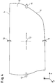
- FIG. 1a section according to line CC in FIG. 1c
- FIG. 1b section according to line CC in FIG. 1c
- connection of the upper edge 4 of the door panel 1 with the profile rail 2 enables the door panel 1 to be moved in the longitudinal direction.
- the shifting of the door paneling 1 is carried out until the lower edge 5 of the paneling is connected to the undercut 6 (see FIG. 2) on the substructure 3, which was previously fitted with a profiled rubber 7.
- the door panel 1 is additionally attached conventionally at four further points (see, for example, FIG. 4) (for example with screws, snaps, rivets, centering ribs). With these four additional fastening connections, movement in one of two directions (x or z) is permitted.
- elongated holes 9, 10, 11, 12, which specify the free direction of movement. This ensures that the door paneling cannot move in an uncontrolled manner on the substructure 3 and has an imaginary attachment point 13 in the middle of the surface.
- the imaginary attachment point 13 can optionally be positioned at any point on the planking surface.
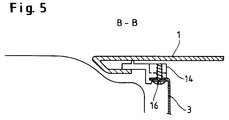
- an injection-molded profile 14 can also be used, which is previously inserted into the undercut 6 and, after reaching the end position of the door panel 1 (see, for example, FIG. 1e), is fastened to the substructure 3 (for example with screws 16, snapper etc.).
Abstract
Description
- Die Erfindung betrifft eine demontierbare Karosserieverkleidung, insbesondere ein System zur Befestigung von Karosserieflächen und Verkleidungsteilen - nachfolgend als Beplankung bezeichnet -, die tragende Unterkonstruktionen (Tragestrukturen) von Fahrzeugen verkleidet. Die Beplankung kann insbesondere bei der großserientechnischen Montage bzw. Demontage von Karosserieverkleidungen von Fahrzeugen eingesetzt werden. Die Beplankung kompensiert Fertigungstoleranzen und/oder Maßänderungen durch Temperaturschwankungen, die bei der Beplankung von Tragstrukturen zu berücksichtigen sind.
- Bei der Befestigung von Beplankungen auf einer tragenden Unterkonstruktion mit einem stark unterschiedlichen thermischen Ausdehnungsverhalten von Beplankung und Unterkonstruktion zueinander sind derzeit folgende Lösungen bekannt:
- 1. Befestigung der Beplankung durch eine Schraubverbindung mit Langlöchern an der Beplankung. Diese ermöglichen eine Ausdehnung der Beplankung in einer Richtung.
- 2. Die Befestigung der Beplankung erfolgt durch Gleitlager, die durch eine Schraub- oder Nietverbindung an der Tragestruktur gehalten werden und mit einem entsprechenden Gegenlager in der Beplankung einen Gleitsitz ergeben: Dieses ermöglicht eine Ausdehnungsfreiheit der Beplankung in einer Dimension, durch Doppellager in zwei Dimensionen.
- 3. Die Befestigung der Beplankung durch in die Beplankung integrierte Gewindebolzen mit Langlochflanschen in der Unterkonstruktion. Diese Befestigungsart ermöglicht eine Ausdehnungsfreiheit der Beplankung in einer Dimension.
- 4. Die Befestigung der Beplankung durch eine feste Schraubverbindung über integrierte Biegeflansche an der Beplankung. Diese ermöglicht eine Ausdehnungsfreiheit der Beplankung ebenfalls in einer Dimension.
- Alle genannten Befestigungssysteme erfordern eine zusätzliche Abdichtung zwischen Beplankung und Tragestruktur, um eine Spritzwasser- bzw. Staubdichtigkeit zu erreichen und um die Entstehung von Klapper- oder Knarrgeräuschen zwischen Beplankung und Tragestruktur zu vermeiden.
- Die deutsche Patentschrift DE 39 35 857 C1 beschreibt eine Kraftfahrzeugtür bei der auf einem tragenden Grundkörper ein Türblatt befestigt ist, in dem ein korrespondierendes Ränderpaar von Türblatt und Grundkörper Nuten aufweist, die zueinander öffnen und durch einen Profilstreifen miteinander verbunden sind. Dieses Befestigungssystem ermöglicht eine lösbare Verbindung zwischen Grundkörper und Türblatt.
- Nachteilig ist bei diesem Befestigungssystem, daß bei einem Erwärmen des Türblattes gegenüber dem Grundkörper aufgrund z.B. unterschiedlicher Wärmeausdehnung der Materialien die Festigkeit der Verbindung nicht mehr ausreichend ist, beispielsweise gegenüber unerwünschter Demontage. Die Einbruchsicherheit von Kraftfahrzeugen ist damit unter Umständen nicht mehr gewährleistet.
- Der Erfindung liegt die Aufgabe zugrunde, ein Befestigungssystem zu entwickeln, bei dem steife Unterkonstruktionen mit großflächigen Beplankungen verkleidet werden. Das System sollte einfach in der Handhabung und in der Produktion wirtschaftlich zu montieren und demontieren sein. Wichtige Kriterien sind Einbruchsicherheit, Dichtigkeit sowie das Vermeiden von Knarr- und Klappergeräuschen. Das Befestigungssystem darf keine sichtbaren Markierungen auf der Sichtfläche der Beplankung verursachen.
- Die Aufgabe wird erfindungsgemäß gelöst durch eine Karosserieverkleidung bestehend aus mindestens einer Beplankung und einer Tragestruktur, dadurch gekennzeichnet, daß die Beplankung an ihrer Umfangskante Falzkanten aufweist, die über Befestigungskanten der Tragestruktur greifen und als Nut-Federkombination mit einem zwischenliegenden Profil eine Verbindung bilden.
- Weitere bevorzugte Ausführungsformen sind den Unteransprüchen zu entnehmen.
- Die erfindungsgemäße Verkleidung läßt insbesondere bei vier zusätzlichen Befestigungsverbindungen eine unbehinderte Längenausdehnung Δ L der Beplankung in zwei Dimensionen (hier als x- und z-Richtung bezeichnet) zu, fixiert die Beplankung aber in der dritten Dimension (hier als y-Richtung bezeichnet) über die Gesamtlänge des Umfangs durchgängig.
- In einer bevorzugten Ausführung ist die Beplankung über vier zusätzliche - pro Beplankungsseite einen - Befestigungspunkte in ihrer Lage zur Tragestruktur eindeutig fixiert. Die Befestigungsverbindungen sind dabei so ausgeführt, daß ein Paar Befestigungsverbindungen in z-, y-Richtung fest, aber in x-Richtung beweglich und ein Paar in x-, y-Richtung fest aber in z-Richtung beweglich gestaltet ist, so daß ein imaginärer absoluter Fixpunkt in der Beplankungsmitte resultiert.
- Mit dem entwickelten Befestigungssystem der Beplankung werden gegenüber dem Stand der Technik folgende Vorteile erzielt:
Durch die besondere konstruktive Gestaltung der Beplankungsumfangskanten und des Zusatzprofils wird eine einfachere Handhabung bei Montage bzw. Demontage der Beplankung erreicht. Insbesondere durch den Einsatz von nur einem Sicherungsprofil oder gegebenenfalls zwei Sicherungsprofilen, wird eine kürzere Montage- bzw. Demontagezeit benötigt. Die Befestigung erfordert keine Zusatzwerkzeuge bei der Montage bzw. Demontage. Die Konstruktion ist besonders platzsparend und garantiert eine spielfreie Verbindung der Beplankung über die Gesamtlänge der Umfangskanten, was eine verbesserte Einbruchsicherheit, Staubund Spritzwasserdichtigkeit und eine gleichmäßige Kraftverteilung auf die Beplankungsfläche zur Folge hat. - Der wesentliche Vorteil der erfindungsgemäßen Karosserieverkleidung ist die Möglichkeit der freien Ausdehnung der Beplankung in zwei Dimensionen. Die daraus resultierenden äußerst niedrigen Bauteilspannungen bei extrem niedriger bzw. erhöhter Temperatur (-30 bis +150°C) sind die denkbar besten Voraussetzungen um Verwerfungen der Beplankungsoberfläche zu vermeiden.
- Des weiteren ergeben sich bei der bevorzugten Verkleidung durch den imaginären Befestigungspunkt zur Tragestruktur auf der Flächenmitte der Beplankung zwei weitere Vorteile:
- Die Längenausdehnung der Beplankung verteilt sich gleichmäßig auf alle Anschlußfugen.
- Ein Verdrehen der Beplankung in bezug auf die Unterkonstruktion ist ausgeschlossen. Dies garantiert stets ein gleichmäßiges Fugenbild.
- Zur Herstellung der Umfangskanten der Beplankung sowie der Tragestruktur eignen sich die im Prinzip bekannten Verfahren: Pressen, Tiefziehen, Fließpressen, Spritzgießen, je nachdem, welcher Werkstoff für die Beplankung bzw. für die Tragestruktur verwendet wird.
- Die zwischenliegenden Befestigungsprofile sind je nach Werkstoff nach dem Extrusions- oder dem Spritzgießverfahren herstellbar.
- Als Material zur Herstellung der Beplankung insbesondere mit einer integrierten Befestigung an den Umfangskanten sind ziehfähige Bleche aus Stahl oder Aluminium sowie Formteile aus duroplastischen bzw. thermoplastischen Kunststoffen geeignet. Als Basismaterial des oder der Zusatzprofile eignen sich thermoplastische Kunststoffe, Elastomere, Kautschuk oder Silikone.
- Die erfindungsgemäße Karosserieverkleidung eignet sich grundsätzlich für alle Arten von Karosserieabdeckungen, insbesondere für die Beplankung von Karosseriestrukturen von Personenkraftwagen oder Lastkraftwagen.
- Die Erfindung wird anhand der Figuren nachstehend beispielhaft näher erläutert. Es zeigen
- Fig. 1 a bis d
- Skizzen zur Erläuterung der Montage einer Ausführungsform der erfindungsgemäßen Beplankung (Kfz-Tür)
- Fig. 2
- einen Schnitt durch eine Befestigungskante eines erfindungsgemäßen Karosserieteiles
- Fig. 3a und b
- einen Schnitt durch die Beplankung nach Fig. 1d entsprechend der Linie B-B bei unterschiedlicher thermischer Längenausdehnung Δ L der Beplankung
- Fig. 4
- schematische Darstellung einer Befestigungsmöglichkeit einer Beplankung nach Fig. 1d zur Erläuterung des imaginären Befestigungspunktes
- Fig. 5
- Variante der Verbindung zwischen Tragestruktur, Profil und Planke entsprechend einem Schnitt B-B in Fig. 1d
- Im folgenden wird die erfindungsgemäße Karosserieverkleidung anhand von demontierbaren Karosserieflächen einer Kraftfahrzeugtürbeplankung gezeigt. Das nachfolgende Befestigungssystem kann unter Berücksichtigung der Fügerichtung und der Designvorgaben auf eine Vielzahl von Karosserieflächen (z.B. Kofferraumdeckel, Heckklappen, Kfz-Dächer) oder z.B. auf die Außenverkleidung von Elektrogeräten übertragen werden.
- In den Zeichnungen 1a bis d der Fig. 1 ist der Montageablauf chronologisch skiziiert. Die Türbeplankung 1 wird unter einem Winkel (Fig. 1a; Schnitt entsprechend Linie C-C in Figur 1c) mit der Oberkante 4 in eine Profilschiene 2 eingesteckt, die mit der Tragestruktur 3 verbunden ist und danach an die Tragestruktur 3 herangeklappt (siehe Fig. 1b) oder über die gesamte Länge seitlich eingeschoben (siehe Fig. 1c).
- Die Verbindung der Oberkante 4 der Türbeplankung 1 mit der Profilschiene 2 ermöglicht ein Verschieben der Türbeplankung 1 in Längsrichtung. Das Verschieben der Türbeplankung 1 (siehe Fig. 1d) wird solange durchgeführt, bis die Unterkante 5 der Beplankung mit dem Hinterschnitt 6 (siehe Fig. 2) auf der Unterstruktur 3 verbunden ist, die zuvor mit einem Profilgummi 7 bestückt wurde.
- Danach wird eine weitere flexible Sicherungsprofilleiste 8 (siehe Fig. 1d) von oben zwischen Hinterschnitt 6 und Tragestruktur 3 geschoben (siehe Fig. 3), so daß die kompletten Umfangskanten der Türbeplankung schwimmend auf der Tragestruktur 3 befestigt sind und somit die gewünschte Spielfreiheit, Dichtheit, Einbruchsicherheit und Kompensation von thermischer Längenausdehnung Δ L damit gewährleistet sind.
- Um ein unkontrolliertes Ausdehnen in unterschiedliche Richtungen oder ein Verdrehen der Türbeplankung 1 auf der Unterstruktur 3 zu unterbinden, wird die Türbeplankung 1 zusätzlich an vier weiteren Punkten (siehe z.B. Fig. 4) konventionell befestigt (z.B. mit Schrauben, Schnappern, Nieten, Zentrierrippen). Bei diesen vier zusätzlichen Befestigungsverbindungen wird jeweils eine Bewegung in einer von zwei Richtungen (x oder z) zugelassen.
- Dies wird durch Langlöcher 9, 10, 11, 12 erreicht, welche die freie Bewegungsrichtung vorgeben. Damit ist gewährleistet, daß sich die Türbeplankung nicht unkontrolliert auf der Unterstruktur 3 verschieben kann und einen imaginären Befestigungspunkt 13 in der Mitte der Fläche besitzt. Der imaginäre Befestigungspunkt 13 kann je nach Lage der Langlöcher 9, 10, 11, 12 wahlweise auf einer beliebigen Stelle der Beplankungsfläche positioniert werden.
- In Abwandlung zur extrudierten, flexiblen Profilleiste 8 kann ebenfalls ein spritzgegossenes Profil 14 eingesetzt werden, das zuvor in den Hinterschnitt 6 eingelegt wird und nach Erreichen der Endposition der Türbeplankung 1 (siehe z.B. Fig. 1e) auf der Unterstruktur 3 befestigt wird (z.B. mit Schrauben 16, Schnapper etc.).
Claims (8)
- Karosserieverkleidung bestehend aus mindestens einer Beplankung 1 und einer Tragestruktur 3, dadurch gekennzeichnet, daß die Beplankung 1 an ihrer Umfangskante Falzkanten 6 aufweist, die über Befestigungskanten 15 der Tragestruktur 3 greifen und als Nut-Federkombination mit einem zwischenliegenden Profil 7 eine Verbindung bilden.
- Karosserieverkleidung gemäß Anspruch 1, dadurch gekennzeichnet, daß an der Umfangskante der Beplankung 1 gegenüberliegend mindestens zwei zusätzliche lösbare Verbindungen 9, 10 zur Tragestruktur 3 angebracht sind.
- Karosserieverkleidung gemäß Anspruch 1 oder 2, dadurch gekennzeichnet, daß die Beplankung 1 an zusätzlichen Stellen der Umfangskante über Zapfenverbindungen fixiert ist.
- Karosserieverkleidung gemäß Anspruch 1 bis 3, dadurch gekennzeichnet, daß sie vier lösbare Verbindungen 9, 10, 11, 12 aufweist die jeweils paarweise an gegenüberliegenden Umfangskanten der Beplankung 1 angebracht sind.
- Karosserieverkleidung nach den Ansprüchen 1 bis 4, dadurch gekennzeichnet, daß ein Profil 8 als einschiebbares elastisches Sicherungsprofil ausgebildet ist.
- Karosserieverkleidung nach den Ansprüchen 1 bis 5, dadurch gekennzeichnet, daß die Profile 7 die Beplankung 1 und Tragestruktur 3 spritzwasserdicht und ausdehnungsfrei miteinander verbinden.
- Karosserieverkleidung nach den Ansprüchen 1 bis 6, dadurch gekennzeichnet, daß als Material für die Beplankung 1 bzw. für die Tragestruktur 3 Bleche aus Stahl oder Aluminium oder duroplastische und/oder thermoplastische flächige Kunststoff-Formteile verwendet werden.
- Verwendung der Karosserieverkleidung nach den Ansprüchen 1 bis 7 zur Verkleidung von Kraftfahrzeugen, insbesondere Personenkraftwagen und Lastkraftwagen.
Applications Claiming Priority (4)
| Application Number | Priority Date | Filing Date | Title |
|---|---|---|---|
| DE19500641 | 1995-01-12 | ||
| DE19500641 | 1995-01-12 | ||
| DE19544668 | 1995-11-30 | ||
| DE19544668A DE19544668A1 (de) | 1995-01-12 | 1995-11-30 | Karosserieverkleidung |
Publications (2)
| Publication Number | Publication Date |
|---|---|
| EP0721861A1 true EP0721861A1 (de) | 1996-07-17 |
| EP0721861B1 EP0721861B1 (de) | 2000-06-21 |
Family
ID=26011539
Family Applications (1)
| Application Number | Title | Priority Date | Filing Date |
|---|---|---|---|
| EP95120538A Expired - Lifetime EP0721861B1 (de) | 1995-01-12 | 1995-12-27 | Karosserieverkleidung |
Country Status (6)
| Country | Link |
|---|---|
| US (1) | US5830559A (de) |
| EP (1) | EP0721861B1 (de) |
| JP (1) | JPH08239055A (de) |
| CA (1) | CA2166853A1 (de) |
| CZ (1) | CZ288843B6 (de) |
| ES (1) | ES2146706T3 (de) |
Cited By (2)
| Publication number | Priority date | Publication date | Assignee | Title |
|---|---|---|---|---|
| EP2101121A1 (de) * | 2008-03-11 | 2009-09-16 | Giordano Riello International Group S.p.A. | Installationsmodul für eine Klimaanlage |
| FR2977836A1 (fr) * | 2011-07-13 | 2013-01-18 | Peugeot Citroen Automobiles Sa | Panneau de garnissage d'une porte de vehicule automobile comprenant une encoche de demontage et procede de demontage d'un tel panneau |
Families Citing this family (18)
| Publication number | Priority date | Publication date | Assignee | Title |
|---|---|---|---|---|
| US5702779A (en) * | 1995-07-17 | 1997-12-30 | Webasto Sunroofs Inc | Plastic panel assembly for use in a vehicle |
| DE19810643C1 (de) * | 1998-03-12 | 1999-08-19 | Daimler Chrysler Ag | Karosserieabschnitt für eine Kraftfahrzeugkarosserie |
| US6523244B1 (en) * | 1999-03-29 | 2003-02-25 | Tesco Engineering, Inc. | Aluminum closure panel and hemming method |
| FR2811631B1 (fr) * | 2000-07-13 | 2002-09-20 | Plastic Omnium Cie | Assemblage de pieces de carrosserie, l'une au moins comportant un film surmoule |
| US20060230686A1 (en) * | 2003-06-10 | 2006-10-19 | Gdx North America Inc | Sealing strip for a closure member |
| US7241073B2 (en) * | 2003-11-21 | 2007-07-10 | Ford Global Technologies, Llc | Sheet metal hem |
| US7052069B2 (en) * | 2004-04-28 | 2006-05-30 | Phyllis Louise Vance | Protective device for a vehicle door |
| US7559599B2 (en) * | 2007-01-30 | 2009-07-14 | Faurecia Interior Systems U.S.A. Inc. | Panel side door structure for a motor vehicle |
| GB2466807B (en) * | 2009-01-08 | 2013-07-03 | Ifor Williams Trailers Ltd | Connection means |
| CN103878258B (zh) * | 2012-12-19 | 2016-03-23 | 钟春雷 | 一种扣接装置 |
| CN104259329B (zh) * | 2014-09-09 | 2016-06-08 | 浙江安德电器有限公司 | 洗碗机内胆的咬边工艺 |
| FR3039801B1 (fr) * | 2015-08-03 | 2018-11-23 | Psa Automobiles Sa. | Piece decor agencee pour etre montee sur un element d’habitacle de vehicule |
| CN106541897B (zh) * | 2015-09-18 | 2019-04-05 | 本田技研工业(中国)投资有限公司 | 汽车行李舱的盖板配合结构 |
| US10118651B2 (en) | 2016-02-11 | 2018-11-06 | Honda Motor Co., Ltd. | Interior body panel fit and finish tabs and methods of installation and use thereof |
| DE102016011744B3 (de) * | 2016-09-29 | 2018-02-22 | Audi Ag | Haltevorrichtung für ein Außenbeplankungselement eines Kraftfahrzeugs, Kraftfahrzeug und Verfahren zum Betätigen einer Haltevorrichtung |
| CN207005033U (zh) * | 2017-01-24 | 2018-02-13 | 市光法雷奥(佛山)汽车照明系统有限公司 | 连接组件 |
| DE102017211014A1 (de) * | 2017-06-29 | 2019-01-03 | Bayerische Motoren Werke Aktiengesellschaft | Karosserierohbauteile und Trägerbauteile, Bauteilanordnung und Fahrzeug |
| FR3114132B1 (fr) * | 2020-09-17 | 2022-09-23 | Alstom Transp Tech | Procédé d’assemblage d’un panneau à un profilé technique pour former un élément d’intérieur de véhicule de transport public |
Citations (5)
| Publication number | Priority date | Publication date | Assignee | Title |
|---|---|---|---|---|
| US1764668A (en) * | 1926-08-02 | 1930-06-17 | Herbert J Woodall | Automobile closed-body construction |
| US1960949A (en) * | 1931-09-24 | 1934-05-29 | Budd Edward G Mfg Co | Upholstery and securing means therefor |
| US2466190A (en) * | 1946-02-23 | 1949-04-05 | Gen Motors Corp | Trim panel assembly |
| US5090762A (en) * | 1990-10-29 | 1992-02-25 | The Excello Specialty Company | Automotive door trim panel protector and method of using the same |
| US5111619A (en) * | 1991-08-12 | 1992-05-12 | General Motors Corporation | Door trim panel retaining assembly |
Family Cites Families (11)
| Publication number | Priority date | Publication date | Assignee | Title |
|---|---|---|---|---|
| JPS49113078U (de) * | 1973-01-31 | 1974-09-26 | ||
| JPS607212Y2 (ja) * | 1979-09-28 | 1985-03-11 | 田村プラスチツク製品株式会社 | 自動車用サイドバイザ− |
| JPS5944570B2 (ja) * | 1979-10-02 | 1984-10-30 | 章雄 飯田 | 水位の模擬装置 |
| FR2576343B1 (fr) * | 1985-01-22 | 1987-03-06 | Philippe Lamberet | Profile de chant pour panneaux isothermiques a parements metalliques et panneaux equipes de ce profile |
| JPH0162148U (de) * | 1987-10-15 | 1989-04-20 | ||
| JPH038947U (de) * | 1989-01-31 | 1991-01-28 | ||
| DE3935857C1 (de) * | 1989-10-27 | 1990-11-29 | Bayer Ag, 5090 Leverkusen, De | |
| JPH0519009U (ja) * | 1991-08-23 | 1993-03-09 | ダイハツ工業株式会社 | トリムボードの取付け構造 |
| US5446999A (en) * | 1993-06-28 | 1995-09-05 | Nissan Motor Co., Ltd. | Vehicle door assembly having an easily removable outside panel |
| JP3214180B2 (ja) * | 1993-09-10 | 2001-10-02 | 日産自動車株式会社 | 樹脂製ドアパネル構造 |
| JPH0939679A (ja) * | 1995-07-31 | 1997-02-10 | Daihatsu Motor Co Ltd | デッキサイドトリムの取付構造 |
-
1995
- 1995-12-27 EP EP95120538A patent/EP0721861B1/de not_active Expired - Lifetime
- 1995-12-27 ES ES95120538T patent/ES2146706T3/es not_active Expired - Lifetime
-
1996
- 1996-01-04 US US08/583,183 patent/US5830559A/en not_active Expired - Fee Related
- 1996-01-05 JP JP8017100A patent/JPH08239055A/ja active Pending
- 1996-01-09 CA CA002166853A patent/CA2166853A1/en not_active Abandoned
- 1996-01-11 CZ CZ199694A patent/CZ288843B6/cs not_active IP Right Cessation
Patent Citations (5)
| Publication number | Priority date | Publication date | Assignee | Title |
|---|---|---|---|---|
| US1764668A (en) * | 1926-08-02 | 1930-06-17 | Herbert J Woodall | Automobile closed-body construction |
| US1960949A (en) * | 1931-09-24 | 1934-05-29 | Budd Edward G Mfg Co | Upholstery and securing means therefor |
| US2466190A (en) * | 1946-02-23 | 1949-04-05 | Gen Motors Corp | Trim panel assembly |
| US5090762A (en) * | 1990-10-29 | 1992-02-25 | The Excello Specialty Company | Automotive door trim panel protector and method of using the same |
| US5111619A (en) * | 1991-08-12 | 1992-05-12 | General Motors Corporation | Door trim panel retaining assembly |
Cited By (2)
| Publication number | Priority date | Publication date | Assignee | Title |
|---|---|---|---|---|
| EP2101121A1 (de) * | 2008-03-11 | 2009-09-16 | Giordano Riello International Group S.p.A. | Installationsmodul für eine Klimaanlage |
| FR2977836A1 (fr) * | 2011-07-13 | 2013-01-18 | Peugeot Citroen Automobiles Sa | Panneau de garnissage d'une porte de vehicule automobile comprenant une encoche de demontage et procede de demontage d'un tel panneau |
Also Published As
| Publication number | Publication date |
|---|---|
| US5830559A (en) | 1998-11-03 |
| CZ9496A3 (en) | 1996-08-14 |
| ES2146706T3 (es) | 2000-08-16 |
| CZ288843B6 (cs) | 2001-09-12 |
| JPH08239055A (ja) | 1996-09-17 |
| EP0721861B1 (de) | 2000-06-21 |
| CA2166853A1 (en) | 1996-07-13 |
Similar Documents
| Publication | Publication Date | Title |
|---|---|---|
| EP0721861B1 (de) | Karosserieverkleidung | |
| EP1088746B1 (de) | Fahrzeugdachmodul mit integrierter Schiebedacheinheit | |
| EP2285612B1 (de) | Profilelement zum verbinden einer fahrzeugscheibe mit einem wasserkasten | |
| DE102009017384B4 (de) | Mehrkomponentige Zierblende für ein Kraftfahrzeug und Verfahren zu seiner Montage | |
| DE19746724C1 (de) | Kraftfahrzeugtür mit einer lösbar befestigten Türaußenwandung | |
| EP2994327A1 (de) | Abdichtungsanordnung für eine feste fahrzeugscheibe | |
| EP0524447A1 (de) | Fenstereinfassrahmen, insbesondere für Fahrzeuge | |
| DE10160676A1 (de) | Kotflügel aus Kunststoff an Kraftfahrzeugen | |
| DE19946008B4 (de) | Verbundbauteil für Fahrzeugkarosserien | |
| EP1429941A1 (de) | Verkleidungselement für das dach eines fahrzeuginnenraums | |
| EP0722880A2 (de) | Kraftfahrzeugdach mit zumindest einem daran befestigten Dachanbauteil sowie Montagevorrichtung für Dachanbauteile | |
| DE102013200689B4 (de) | Befestigungsvorrichtung | |
| DE102015000463A1 (de) | Befestigungsanordnung zur Montage einer Zierblende und/oder einer Scheibenführung an einer Fahrzeugtür | |
| EP3667005B1 (de) | Scharniersystem, fahrzeugaufbau, fahrzeug und verfahren zur montage einer türe | |
| DE102006009345A1 (de) | Verfahren zur Herstellung einer Verbindung zwischen einem faserverstärkten Kunststoffverkleidungsteil und einem Verkleidungsträger | |
| DE102004005963B4 (de) | Befestigungselement | |
| DE19544668A1 (de) | Karosserieverkleidung | |
| DE3241652A1 (de) | Fahrzeugaufbau mit fenster | |
| DE102017216430A1 (de) | Bauteilsystem zur Fixierung eines Verkleidungsteils und Kraftfahrzeug | |
| DE102006021457B4 (de) | Metallverstärkter Kunststoffträger für ein Fahrzeug | |
| DE102007006735B4 (de) | Kraftfahrzeugtür mit Innengriffanordnung | |
| EP3118037B1 (de) | Fensterführungsschiene | |
| EP3020903A1 (de) | Verkleidungshalterung | |
| EP2394010B2 (de) | Türmodul für eine kraftfahrzeugtür mit einer fensterheberanordnung | |
| DE102016203242B4 (de) | Anordnung einer Zierleiste eines Fahrzeugs gegenüber einem anderen Fahrzeugelement |
Legal Events
| Date | Code | Title | Description |
|---|---|---|---|
| PUAI | Public reference made under article 153(3) epc to a published international application that has entered the european phase |
Free format text: ORIGINAL CODE: 0009012 |
|
| AK | Designated contracting states |
Kind code of ref document: A1 Designated state(s): BE CH DE ES FR GB IT LI SE |
|
| RAP1 | Party data changed (applicant data changed or rights of an application transferred) |
Owner name: MC MICRO COMPACT CAR AKTIENGESELLSCHAFT Owner name: BAYER AG |
|
| RIN1 | Information on inventor provided before grant (corrected) |
Inventor name: FREISCHLAEGER, RALF Inventor name: POTHOVEN, ALEXANDER Inventor name: MAROLD, ADOLF Inventor name: MALEK, THOMAS Inventor name: KOCH, BORIS Inventor name: GOLDBACH, HUBERT |
|
| 17P | Request for examination filed |
Effective date: 19961218 |
|
| 17Q | First examination report despatched |
Effective date: 19980407 |
|
| RAP1 | Party data changed (applicant data changed or rights of an application transferred) |
Owner name: MICRO COMPACT CAR AG Owner name: BAYER AG |
|
| GRAG | Despatch of communication of intention to grant |
Free format text: ORIGINAL CODE: EPIDOS AGRA |
|
| GRAG | Despatch of communication of intention to grant |
Free format text: ORIGINAL CODE: EPIDOS AGRA |
|
| GRAH | Despatch of communication of intention to grant a patent |
Free format text: ORIGINAL CODE: EPIDOS IGRA |
|
| GRAH | Despatch of communication of intention to grant a patent |
Free format text: ORIGINAL CODE: EPIDOS IGRA |
|
| GRAA | (expected) grant |
Free format text: ORIGINAL CODE: 0009210 |
|
| RAP1 | Party data changed (applicant data changed or rights of an application transferred) |
Owner name: MICRO COMPACT CAR SMART GMBH Owner name: BAYER AG |
|
| AK | Designated contracting states |
Kind code of ref document: B1 Designated state(s): BE CH DE ES FR GB IT LI SE |
|
| REG | Reference to a national code |
Ref country code: CH Ref legal event code: NV Representative=s name: E. BLUM & CO. PATENTANWAELTE Ref country code: CH Ref legal event code: EP |
|
| GBT | Gb: translation of ep patent filed (gb section 77(6)(a)/1977) |
Effective date: 20000621 |
|
| REF | Corresponds to: |
Ref document number: 59508491 Country of ref document: DE Date of ref document: 20000727 |
|
| REG | Reference to a national code |
Ref country code: ES Ref legal event code: FG2A Ref document number: 2146706 Country of ref document: ES Kind code of ref document: T3 |
|
| ITF | It: translation for a ep patent filed |
Owner name: SOCIETA' ITALIANA BREVETTI S.P.A. |
|
| ET | Fr: translation filed | ||
| PLBE | No opposition filed within time limit |
Free format text: ORIGINAL CODE: 0009261 |
|
| STAA | Information on the status of an ep patent application or granted ep patent |
Free format text: STATUS: NO OPPOSITION FILED WITHIN TIME LIMIT |
|
| 26N | No opposition filed | ||
| REG | Reference to a national code |
Ref country code: GB Ref legal event code: IF02 |
|
| PGFP | Annual fee paid to national office [announced via postgrant information from national office to epo] |
Ref country code: ES Payment date: 20051201 Year of fee payment: 11 |
|
| PGFP | Annual fee paid to national office [announced via postgrant information from national office to epo] |
Ref country code: FR Payment date: 20051207 Year of fee payment: 11 |
|
| PGFP | Annual fee paid to national office [announced via postgrant information from national office to epo] |
Ref country code: SE Payment date: 20051214 Year of fee payment: 11 |
|
| PGFP | Annual fee paid to national office [announced via postgrant information from national office to epo] |
Ref country code: CH Payment date: 20051215 Year of fee payment: 11 |
|
| PGFP | Annual fee paid to national office [announced via postgrant information from national office to epo] |
Ref country code: GB Payment date: 20051221 Year of fee payment: 11 |
|
| PGFP | Annual fee paid to national office [announced via postgrant information from national office to epo] |
Ref country code: BE Payment date: 20060116 Year of fee payment: 11 |
|
| PG25 | Lapsed in a contracting state [announced via postgrant information from national office to epo] |
Ref country code: SE Free format text: LAPSE BECAUSE OF NON-PAYMENT OF DUE FEES Effective date: 20061228 |
|
| PG25 | Lapsed in a contracting state [announced via postgrant information from national office to epo] |
Ref country code: LI Free format text: LAPSE BECAUSE OF NON-PAYMENT OF DUE FEES Effective date: 20061231 Ref country code: CH Free format text: LAPSE BECAUSE OF NON-PAYMENT OF DUE FEES Effective date: 20061231 Ref country code: BE Free format text: LAPSE BECAUSE OF NON-PAYMENT OF DUE FEES Effective date: 20061231 |
|
| PGFP | Annual fee paid to national office [announced via postgrant information from national office to epo] |
Ref country code: IT Payment date: 20061231 Year of fee payment: 12 |
|
| REG | Reference to a national code |
Ref country code: CH Ref legal event code: PL |
|
| EUG | Se: european patent has lapsed | ||
| GBPC | Gb: european patent ceased through non-payment of renewal fee |
Effective date: 20061227 |
|
| REG | Reference to a national code |
Ref country code: FR Ref legal event code: ST Effective date: 20070831 |
|
| PG25 | Lapsed in a contracting state [announced via postgrant information from national office to epo] |
Ref country code: GB Free format text: LAPSE BECAUSE OF NON-PAYMENT OF DUE FEES Effective date: 20061227 |
|
| BERE | Be: lapsed |
Owner name: *MICRO COMPACT CAR SMART G.M.B.H. Effective date: 20061231 Owner name: *BAYER A.G. Effective date: 20061231 |
|
| REG | Reference to a national code |
Ref country code: ES Ref legal event code: FD2A Effective date: 20061228 |
|
| PG25 | Lapsed in a contracting state [announced via postgrant information from national office to epo] |
Ref country code: FR Free format text: LAPSE BECAUSE OF NON-PAYMENT OF DUE FEES Effective date: 20070102 Ref country code: ES Free format text: LAPSE BECAUSE OF NON-PAYMENT OF DUE FEES Effective date: 20061228 |
|
| PGFP | Annual fee paid to national office [announced via postgrant information from national office to epo] |
Ref country code: DE Payment date: 20081219 Year of fee payment: 14 |
|
| PG25 | Lapsed in a contracting state [announced via postgrant information from national office to epo] |
Ref country code: IT Free format text: LAPSE BECAUSE OF NON-PAYMENT OF DUE FEES Effective date: 20071227 |
|
| PG25 | Lapsed in a contracting state [announced via postgrant information from national office to epo] |
Ref country code: DE Free format text: LAPSE BECAUSE OF NON-PAYMENT OF DUE FEES Effective date: 20100701 |