EP0718637B1 - Système radar - Google Patents
Système radar Download PDFInfo
- Publication number
- EP0718637B1 EP0718637B1 EP95309257A EP95309257A EP0718637B1 EP 0718637 B1 EP0718637 B1 EP 0718637B1 EP 95309257 A EP95309257 A EP 95309257A EP 95309257 A EP95309257 A EP 95309257A EP 0718637 B1 EP0718637 B1 EP 0718637B1
- Authority
- EP
- European Patent Office
- Prior art keywords
- signal
- pulse
- phase difference
- radar
- difference
- Prior art date
- Legal status (The legal status is an assumption and is not a legal conclusion. Google has not performed a legal analysis and makes no representation as to the accuracy of the status listed.)
- Expired - Lifetime
Links
Images
Classifications
-
- G—PHYSICS
- G01—MEASURING; TESTING
- G01S—RADIO DIRECTION-FINDING; RADIO NAVIGATION; DETERMINING DISTANCE OR VELOCITY BY USE OF RADIO WAVES; LOCATING OR PRESENCE-DETECTING BY USE OF THE REFLECTION OR RERADIATION OF RADIO WAVES; ANALOGOUS ARRANGEMENTS USING OTHER WAVES
- G01S13/00—Systems using the reflection or reradiation of radio waves, e.g. radar systems; Analogous systems using reflection or reradiation of waves whose nature or wavelength is irrelevant or unspecified
- G01S13/02—Systems using reflection of radio waves, e.g. primary radar systems; Analogous systems
- G01S13/06—Systems determining position data of a target
- G01S13/08—Systems for measuring distance only
- G01S13/10—Systems for measuring distance only using transmission of interrupted, pulse modulated waves
-
- G—PHYSICS
- G01—MEASURING; TESTING
- G01S—RADIO DIRECTION-FINDING; RADIO NAVIGATION; DETERMINING DISTANCE OR VELOCITY BY USE OF RADIO WAVES; LOCATING OR PRESENCE-DETECTING BY USE OF THE REFLECTION OR RERADIATION OF RADIO WAVES; ANALOGOUS ARRANGEMENTS USING OTHER WAVES
- G01S13/00—Systems using the reflection or reradiation of radio waves, e.g. radar systems; Analogous systems using reflection or reradiation of waves whose nature or wavelength is irrelevant or unspecified
- G01S13/02—Systems using reflection of radio waves, e.g. primary radar systems; Analogous systems
- G01S13/06—Systems determining position data of a target
- G01S13/08—Systems for measuring distance only
- G01S13/32—Systems for measuring distance only using transmission of continuous waves, whether amplitude-, frequency-, or phase-modulated, or unmodulated
- G01S13/36—Systems for measuring distance only using transmission of continuous waves, whether amplitude-, frequency-, or phase-modulated, or unmodulated with phase comparison between the received signal and the contemporaneously transmitted signal
-
- G—PHYSICS
- G01—MEASURING; TESTING
- G01S—RADIO DIRECTION-FINDING; RADIO NAVIGATION; DETERMINING DISTANCE OR VELOCITY BY USE OF RADIO WAVES; LOCATING OR PRESENCE-DETECTING BY USE OF THE REFLECTION OR RERADIATION OF RADIO WAVES; ANALOGOUS ARRANGEMENTS USING OTHER WAVES
- G01S13/00—Systems using the reflection or reradiation of radio waves, e.g. radar systems; Analogous systems using reflection or reradiation of waves whose nature or wavelength is irrelevant or unspecified
- G01S13/88—Radar or analogous systems specially adapted for specific applications
- G01S13/93—Radar or analogous systems specially adapted for specific applications for anti-collision purposes
- G01S13/931—Radar or analogous systems specially adapted for specific applications for anti-collision purposes of land vehicles
Definitions
- the present invention relates to a radar system designed to detect a target from extremely short to long distances away.
- Pulse radar systems are well known. Such a system is designed to transmit a high frequency carrier in a pulse modulated state, receive reflected waves from the target, and find a range to a target on the basis of the time difference from transmission to reception of each pulse. These pulse radar systems have an advantage in that they are capable of detecting a plurality of targets in different ranges.
- Japanese Patent Laid-Open Publication Nos. SHO 57-142575 and SHO 57-166573 show a microwave telerometer for measuring a range to a target on the basis of the phase difference between a low frequency transmission signal and a received low frequency signal obtained by amplitude-modulating a microwave signal with a low frequency transmission signal, transmitting the AM'd transmission signal, receiving and amplifying the AM'd transmission signal reflected by a target, and AM-detecting the low frequency transmission signal in the amplified, received signal.
- a reflected wave may come back during the duration of the transmission, causing the reflected wave to become difficult to be sensed, resulting in inability of short range detection.
- long range detection is difficult, because the measurable range is limited by the wavelength of the low frequency signal used for the modulation.
- JP 56133669A discloses a radar system with switched dual mode pulse and continuous wave (CW) radar.
- the system uses pulse / CW controller to send out either a pulse wave or a CW wave.
- JP 60039579A also describes a switched dual mode radar. This switches from a pulse tracking radar using the Doppler frequency to a CW tracking radar.
- a radar system adapted to transmit a high-frequency signal, receive a signal reflected by a target and detect a range to the target based on the time difference between the transmitted signal and received signal, said radar system comprising:
- the radar system can detect a target from a very close range to a long range by performing a long range detection using the pulse radar mode and by performing a short range detection using the phase difference radar mode. Also, the pulse radar mode enables detection of a plurality of targets in different ranges.
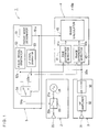
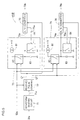
- Fig. 1 a radar system according to an embodiment of the present invention is shown in block diagram form
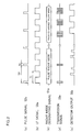
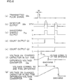
- Fig. 2 a timing chart of the radar mode switching operation in the radar system is shown.
- the radar system 1 comprises a transmitter 2, a receiver 3, a signal processor 4 and a radar mode control 5.
- the transmitter 2 comprises a high-frequency signal oscillator 21 for generating a high frequency (HF) signal in a millimetric wave band, a switching device 22 and a transmitting antenna 23.
- the receiver 3 comprises a receiving antenna 31, a high-frequency amplifier 32 and a detector 33.
- the signal processor 4 comprises a time difference detector 41, a phase difference detector 42 and a range calculator 43.
- the radar mode control 5 comprises a radar mode designator 51, a pulse signal generator 52, a low-frequency (LF) signal generator 53, and a modulating signal selector 54.
- the pulse signal generator 52 outputs a pulse signal 52a with a pulse repeat period TP and pulse width (duration) tp as shown in Fig. 2(a).
- the pulse width tp is designed to be shorter than the pulse repeat period TP so that transmitted and reflected pulses do not conflict.
- the LF signal generator 53 outputs an LF signal 53a comprised of rectangular waves with the period TI as shown in Fig. 2(b).
- the radar mode designator 51 outputs a radar mode designating signal 51a for alternately designating the pulse radar mode and the phase-difference radar mode in respective time slots as shown in Fig. 2(c).
- the modulating signal selector 54 selectively supplies the pulse signal 52a or the LF signal 53a as a modulating signal 54a to the switching device 22 based on whether the radar mode signal 51a is the pulse or phase-difference radar mode.
- a pulse-modulated signal 22a obtained by pulse modulating the millimetric-wave-band HF signal 21a is radiated as electromagnetic waves from the transmitting antenna 23, and in the phase-difference radar mode, a signal 22a obtained by intermittently modulating the HF signal 21a with the LF signal 53a is radiated as electromagnetic waves, as shown in Fig. 2(d).
- the HF signal 21a may be so modulated as to binarize the magnitude of the HF signal on the basis of the LF signal 53a.
- the LF signal generator 53 may be formed of an LF sine signal generator for generating a sine signal to amplitude modulate the HF signal on the basis of the sine signal for radiating as electromagnetic waves.
- this method requires an amplitude modulator.
- intermittent modulation of the HF signal 21a by means of the switching device eliminates the need of the amplitude modulator, which further simplifies the structure of the transmitter 2, because the switching device 22 can be commonly used in both the pulse and phase-difference radar mode.
- the electromagnetic waves radiated from the transmitting antenna 23 are reflected by an object such as a target, and the reflected electromagnetic waves are received by the receiving antenna 31, amplified in the HF amplifier 32, and demodulated in the detector 33.
- An example of the detector output 33a is shown in Fig. 2(e).
- the time difference detector 41 is so arranged as to detect the time difference between the pulse signal 52a and the detector output 33a and to output time difference data 41a.
- the phase difference detector 42 is so arranged as to detect the phase difference between the LF signal 53a and the detector output 33a and to output phase difference data 42a.
- the range calculator 43 calculates a range to a target from the time difference data 41a in the case of the pulse radar mode of the radar mode designating signal 51a and from the phase-difference data 42a in the case of the phase-difference radar mode of the radar mode designating signal 51a, and outputs range data 43a.
- the pulse radar mode and the phase-difference radar mode can be switched from one to the other, so that the radar system can detect a target from a very close range to a long range by performing long range detection using the pulse radar mode and by performing short range detection using the phase-difference radar mode.
- the pulse radar mode enables a plurality of targets in different ranges to be identified. Accordingly, a vehicle mounting the radar system 1 can detect, for example, another vehicle a few meters to tens of meters ahead using the pulse radar mode, and, in case of a right or left turn, or garaging, can detect how many centimetres there are left to an obstacle using the phase difference radar mode.
- the time difference detector 41 may be designed to convert the detector output 33a into a digital signal by means of an A/D converter and detect received pulses and time differences by data processing. If, for example, a target more than one and a half meters away is to be detected, the pulse width tp will be as short as 10 ns, and the sampling frequency of an ordinary A/D converter is insufficient for the detection. Thus, the detector may be designed to obtain the digital signals of the received pulses from a plurality of transmitted pulses taken while shifting the sampling timing by a predetermined time every time a pulse is transmitted.
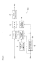
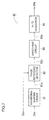
- Fig. 3 is a block diagram of a time difference detector 41A with an extended sampling cycle
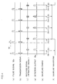
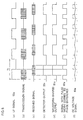
- Fig. 4 is a timing chart illustrating operation of the detector 41A.
- a sampling clock generator 61 generates a clock of a sampling frequency.
- a transmitted pulse counter 62 counts the number of pulses of the pulse signal 52a transmitted in a predetermined cycle TP and supplies the count output 62a to a sampling timing designator 63.
- the sampling timing designator 63 supplies a sampling clock as a sampling timing signal 63a to the sampling timing designator input terminal 64a of the A/D converter 64 when the time corresponding to the count of the transmitted pulses has passed from a rising or falling edge of the pulse signal 52a.
- the sampling timing of the received signal can be shifted by At (one sampling cycle) in each cycle of pulse transmission as shown in Fig. 4(d). That is, it is possible to obtain a sampling wave form which has been extended with respect to time by shifting the sampling point (designated by a small circle) of the detector output 33a during each pulse transmission cycle as shown in Fig. 4(f).
- Writing A/D converted data sequentially in RAM 65 will result in a series of A/D converted data for a received signal.
- a write address control 66 specifies the write addresses to the RAM 65.
- a data processor 67 detects a received pulse from the received data stored in the RAM 65 and outputs time difference data.
- time difference detector 41A shown in Fig. 3 is arranged to obtain one unit of A/D converted data in each pulse transmission cycle
- an alternative arrangement may be employed in which A/D converted data for a plurality of points in one transmission pulse cycle is obtained by generating samples with a time difference of ⁇ txN at times of the transmitted pulse count +N, +2N, +3N and so on, where N is an integer.
- a plurality of A/D converters may be provided which are arranged to be sequentially activated one in each sampling cycle in a shifted way.
- the time difference detector 41B comprises a waveform-shaping circuit 71, a received pulse counter 72, first and second time-difference-to-voltage converters 73 and 74, and first and second A/D converters 75 and 76.
- a pulse shown in Fig. 6(a) is transmitted and a detector output 33a as shown in Fig. 6(b) is obtained.
- Shown in Fig. 6(b), is a case where reflected waves are received from two targets in different ranges.
- the waveform-shaping circuit 71 shapes the waveforms of the detector outputs 33a exceeding a preset threshold value VTH, and outputs a received pulse signal 71a shown in Fig. 6(c).
- a received pulse counter 72 counts the received pulses 71a on the basis of the rise of the received pulse signal 71a output from the waveform-shaping circuit 71 after having been reset at a rise time of the transmitted pulse signal 52a.
- the received pulse counter 72 outputs the first count output Q1 when it counts the first received pulse and outputs the second count output Q2 when it counts the second received pulse, as shown in Figs. 6(d) and 6(e).
- Each of the time-difference-to-voltage converters 73 and 74 comprises a constant current source 81, a charge control 82, a capacitor 83 and a discharge circuit 84. Discussion will be made hereinbelow as to the arrangement and operation of the first time-difference-to-voltage converter 73 and the first A/D converter 75.
- a charge control circuit 82 on detecting a rising edge of the pulse signal 52a, starts charging the capacitor 83, and stops charging when the count output Q1 is supplied.
- An A/D converter 75 samples and holds the voltage on the charged capacitor 83 at the time of rising of the count output Q1. When the A/D converter 75 completes an A/D conversion operation, it outputs a conversion end signal 75a.
- the discharge circuit 84 causes the capacitor 83 to discharge the electric charge on capacitor 83.
- the first time-difference-to-voltage converter 73 outputs a voltage signal 73a relative to the time tl from the transmission of a pulse to the detection of the first reflected signal as shown in Fig. 6(f).
- the voltage signal 73a is A/D converted by the first A/D converter 75 into digital data 75b relative to the time difference for the first target.
- the second time-difference-to-voltage converter 74 outputs a voltage signal 74a relative to the time t2 from the transmission of the pulse to the detection of the second reflected signal as shown in Fig. 6(g).
- the voltage signal 74a is A/D converted by the second A/D converter 76 into digital data 76b relative to the time difference for the second target. It should be noted that three or more time-difference-to-voltage converters may be provided so that three or more targets can be detected.
- time difference can be obtained with a conventional A/D converter by generating a voltage corresponding to the time difference between the transmitted and received signals and detecting the range to the target on the basis of the voltage.
- the phase difference detector 42 comprises a waveform-shaping circuit 81 for generating a waveform-shaped output 81a obtained by shaping and binarizing the waveform of the detector output 33a, a phase difference detecting circuit 82 for detecting the phase difference between the LF signal 53a equivalent to the transmitted signal and the waveform-shaped output 81a and for outputting a signal 82a the pulse width of which is responsive to the phase difference, a smoothing circuit 83 for smoothing the signal 82a with a pulse width responsive to the phase difference and for outputting a DC voltage signal 83a, and an A/D converter 84 for A/D converting the smoothed output 83a to output data 84a relative to the phase difference.
- the phase difference detecting circuit 82 is formed of, e.g., an exclusive OR circuit, and outputs a signal 82a with a pulse width corresponding to the phase difference as shown in Fig. 8(e).
- the signal 82a is smoothed by the smoothing circuit 83 to obtain a DC voltage signal 83a as shown in Fig. 8(f). It is noted that Fig.
- FIG. 8(f) shows a situation where smoothing by means of a smoothing circuit 83 having a relatively long charging time constant yields a pulsating voltage signal while an integration circuit with a short charging time constant and a long discharging time constant may be used to integrate the signal 82a pulses within a predetermined period of time or the signal 82a pulses corresponding to a predetermined number of LF modulating signal 53a pulses, and then the integrated output voltage may be analog-to-digital converted.
- the smoothed output advantageously contains fewer pulsating components, because the output signal 82a of the phase difference detecting circuit 82 comprises two different kinds of pulses, namely, one corresponding to the phase difference between the rising edges of a modulating signal 53a (transmitted signal) pulse and the corresponding waveform-shaped output 81a (received signal) pulse and the other corresponding to the phase difference between the falling edges of them.
- the duration of a waveform-shaped output 81a (or detector output 33a) pulse may become longer than that of the corresponding modulating signal 53a pulse, because the time difference corresponding to the distance between the relevant targets has been added to the time of receipt of the falling edge of the received signal pulse.
- the above described phase difference between the rising edges and that between the falling edges are different, that is, the latter is larger than the former, resulting in the measured range being longer than the actual distance with respect to the target at a shortest distance.
- the phase difference detecting circuit 82 may be arranged such that it outputs a signal comprising pulses each corresponding to the time period from the rising edge of the transmission signal to that of the received signal.
- the radar system can detect a target from a very close range to a long range by performing the long range detection using the pulse radar mode and by performing the short range detection using the phase-difference radar mode. Also, the pulse radar mode enables detection of a plurality of targets in different ranges.
- Switching from one mode to the other may be carried out in any suitable manner. It may be automatic, and may be carried out in such a manner that only the phase-difference mode is used when the vehicle speed is low. It may also be carried out in such a manner that when the vehicle speed exceeds a predetermined speed, such as for example 60 Km/h, the pulse mode and phase-difference mode are switched in a time-sharing fashion.
- a predetermined speed such as for example 60 Km/h
Landscapes
- Engineering & Computer Science (AREA)
- Radar, Positioning & Navigation (AREA)
- Remote Sensing (AREA)
- Computer Networks & Wireless Communication (AREA)
- Physics & Mathematics (AREA)
- General Physics & Mathematics (AREA)
- Radar Systems Or Details Thereof (AREA)
Claims (9)
- Système radar (1) adapté à l'émission d'un signal haute fréquence, la réception d'un signal réfléchi par une cible et la détection d'une distance de la cible basée sur la différence de temps entre le signal émis et le signal reçu, ledit système radar comprenant :caractérisé en ce que le système radar comprend :un mode radar à impulsions pour émettre un signal haute fréquence comme une impulsion de largeur étroite par rapport à un cycle d'émission répété et détecter ladite distance de ladite cible basée sur la différence de temps entre l'émission et la réception de ladite impulsion ; etun mode radar à différence de phase pour émettre un signal obtenu par modulation d'amplitude d'un signal haute fréquence avec un signal basse fréquence, et détecter ladite distance de ladite cible basée sur la différence de phase entre ledit signal basse fréquence émis et un signal basse fréquence obtenu en détectant un signal reçu réfléchi par ladite cible ; etdes moyens de commutation (5) pour permettre une utilisation commutée dudit mode radar à impulsions et dudit mode radar à différence de phase.
- Système radar (1) selon la revendication 1, comprenant en outre :une antenne émettrice (23) ;un oscillateur haute fréquence (21) pour générer un signal haute fréquence dans une bande d'onde millimétrique ; etun dispositif de commutation (54) disposé entre ledit oscillateur haute fréquence (21) et ladite antenne (23), et étant capable d'une opération de commutation pour permettre l'émission de ladite impulsion de largeur étroite et dudit signal haute fréquence modulé avec ledit signal basse fréquence.
- Système radar selon la revendication 1 ou 2, dans lequel ledit signal basse fréquence module par intermittence ledit signal HF.
- Système radar selon la revendication 1, 2 ou 3, comprenant en outre des moyens de décalage (41A) adaptés au fonctionnement dans ledit mode radar à impulsions afin de décaler séquentiellement un instant d'échantillonnage pour une conversion A/N d'une impulsion reçue chaque fois qu'une émission d'impulsion est répétée, afin d'obtenir des données d'impulsions reçues à base de temps étendue.
- Système radar selon la revendication 1, 2 ou 3, comprenant en outre un convertisseur de différence de temps en tension (73, 74) adapté au fonctionnement dans ledit mode radar à impulsions afin de générer une tension correspondant à ladite différence de temps entre une impulsion émise et une impulsion reçue, qui doit subir une conversion A/N afin d'obtenir une donnée relative à ladite différence de temps.
- Système radar selon l'une quelconque des revendications précédentes, dans lequel une pluralité de cibles dans des portées différentes sont détectées par ledit mode radar à impulsions.
- Dispositif selon l'une quelconque des revendications précédentes, comprenant en outre :un détecteur de différence de phase (82) adapté au fonctionnement dans ledit mode radar à différence de phase afin de détecter ladite différence de phase entre ledit signal basse fréquence, utilisé pour moduler ledit signal haute fréquence, et une version mise en forme dudit signal reçu, et de sortir un signal impulsionnel relatif à ladite différence de phase ;un circuit de lissage (83) adapté au fonctionnement dans ledit mode radar à différence de phase afin de lisser ledit signal impulsionnel sorti dudit détecteur de différence de phase et de fournir un signal continu ; etun convertisseur A/N (84) adapté au fonctionnement dans ledit mode radar à différence de phase afin d'effectuer une conversion A/N dudit signal continu de manière à obtenir une donnée relative à ladite différence de phase.
- Système radar selon l'une quelconque des revendications 1 à 6, comprenant en outre :un détecteur de différence de phase (42) adapté au fonctionnement dans ledit mode radar à différence de phase afin de détecter ladite différence de phase entre ledit signal basse fréquence, utilisé pour moduler ledit signal haute fréquence, et une version d'onde mise en forme dudit signal reçu de manière à fournir un signal impulsionnel relatif à ladite différence de phase ;un circuit d'intégration adapté au fonctionnement dans ledit mode radar à différence de phase afin d'intégrer ledit signal impulsionnel sorti dudit détecteur de différence de phase (42) pendant un temps prédéterminé ou un certain nombre de fois d'une émission intermittente de manière à fournir une tension de sortie intégrée ; etun convertisseur A/N adapté au fonctionnement dans ledit mode radar à différence de phase afin d'effectuer une conversion A/N de ladite tension de sortie de manière à obtenir une donnée relative à ladite différence de phase.
- Système radar selon la revendication 7 ou 8, dans lequel lesdits moyens de détection de différence de phase (82) comprennent un circuit OU exclusif.
Applications Claiming Priority (3)
| Application Number | Priority Date | Filing Date | Title |
|---|---|---|---|
| JP31682194 | 1994-12-20 | ||
| JP316821/94 | 1994-12-20 | ||
| JP31682194A JP3294726B2 (ja) | 1994-12-20 | 1994-12-20 | レーダ装置 |
Publications (3)
| Publication Number | Publication Date |
|---|---|
| EP0718637A2 EP0718637A2 (fr) | 1996-06-26 |
| EP0718637A3 EP0718637A3 (fr) | 1998-03-18 |
| EP0718637B1 true EP0718637B1 (fr) | 2001-06-13 |
Family
ID=18081296
Family Applications (1)
| Application Number | Title | Priority Date | Filing Date |
|---|---|---|---|
| EP95309257A Expired - Lifetime EP0718637B1 (fr) | 1994-12-20 | 1995-12-19 | Système radar |
Country Status (4)
| Country | Link |
|---|---|
| US (1) | US5686921A (fr) |
| EP (1) | EP0718637B1 (fr) |
| JP (1) | JP3294726B2 (fr) |
| DE (1) | DE69521282T2 (fr) |
Families Citing this family (38)
| Publication number | Priority date | Publication date | Assignee | Title |
|---|---|---|---|---|
| DE19624043A1 (de) * | 1996-06-17 | 1997-12-18 | Bayerische Motoren Werke Ag | Meßverfahren für den Abstand zwischen einem Kraftfahrzeug und einem Objekt |
| US6067040A (en) * | 1997-05-30 | 2000-05-23 | The Whitaker Corporation | Low cost-high resolution radar for commercial and industrial applications |
| US6069581A (en) * | 1998-02-20 | 2000-05-30 | Amerigon | High performance vehicle radar system |
| US6380883B1 (en) | 1998-02-23 | 2002-04-30 | Amerigon | High performance vehicle radar system |
| US6400308B1 (en) | 1998-02-20 | 2002-06-04 | Amerigon Inc. | High performance vehicle radar system |
| US6137438A (en) * | 1998-07-22 | 2000-10-24 | Thomas E. McEwan | Precision short-range pulse-echo systems with automatic pulse detectors |
| US6614395B2 (en) * | 1998-07-24 | 2003-09-02 | Trimble Navigation Limited | Self-calibrating electronic distance measurement instrument |
| US7908077B2 (en) | 2003-06-10 | 2011-03-15 | Itt Manufacturing Enterprises, Inc. | Land use compatibility planning software |
| US8203486B1 (en) | 1999-03-05 | 2012-06-19 | Omnipol A.S. | Transmitter independent techniques to extend the performance of passive coherent location |
| US7570214B2 (en) | 1999-03-05 | 2009-08-04 | Era Systems, Inc. | Method and apparatus for ADS-B validation, active and passive multilateration, and elliptical surviellance |
| US7777675B2 (en) | 1999-03-05 | 2010-08-17 | Era Systems Corporation | Deployable passive broadband aircraft tracking |
| US7612716B2 (en) | 1999-03-05 | 2009-11-03 | Era Systems Corporation | Correlation of flight track data with other data sources |
| US7667647B2 (en) | 1999-03-05 | 2010-02-23 | Era Systems Corporation | Extension of aircraft tracking and positive identification from movement areas into non-movement areas |
| US7739167B2 (en) | 1999-03-05 | 2010-06-15 | Era Systems Corporation | Automated management of airport revenues |
| US7782256B2 (en) | 1999-03-05 | 2010-08-24 | Era Systems Corporation | Enhanced passive coherent location techniques to track and identify UAVs, UCAVs, MAVs, and other objects |
| US7889133B2 (en) | 1999-03-05 | 2011-02-15 | Itt Manufacturing Enterprises, Inc. | Multilateration enhancements for noise and operations management |
| US8446321B2 (en) | 1999-03-05 | 2013-05-21 | Omnipol A.S. | Deployable intelligence and tracking system for homeland security and search and rescue |
| WO2003027709A1 (fr) * | 2001-09-21 | 2003-04-03 | Siemens Aktiengesellschaft | Detecteur radar pour courtes distances, a mesure de dephasage |
| JP3538183B2 (ja) * | 2002-02-14 | 2004-06-14 | 三菱電機株式会社 | パルスレーダ装置 |
| JP2006038819A (ja) * | 2004-06-25 | 2006-02-09 | Macnica Inc | データ通信装置および方法 |
| US7236235B2 (en) * | 2004-07-06 | 2007-06-26 | Dimsdale Engineering, Llc | System and method for determining range in 3D imaging systems |
| JP4551145B2 (ja) | 2004-07-13 | 2010-09-22 | 富士通株式会社 | レーダ装置、レーダ装置の制御方法 |
| DE102004062023B4 (de) * | 2004-12-23 | 2021-12-23 | Robert Bosch Gmbh | Radarsystem zur Überwachung von Zielen in verschiedenen Entfernungsbereichen |
| US7327308B2 (en) * | 2005-04-28 | 2008-02-05 | Chung Shan Institute Of Science And Technology, Armaments Bureau, M.N.D. | Programmable method and test device for generating target for FMCW radar |
| JP2007171031A (ja) * | 2005-12-22 | 2007-07-05 | Aisin Seiki Co Ltd | 電波式距離センサ |
| US7965227B2 (en) | 2006-05-08 | 2011-06-21 | Era Systems, Inc. | Aircraft tracking using low cost tagging as a discriminator |
| US20100265121A1 (en) | 2008-09-02 | 2010-10-21 | Preco Electronics, Inc. | Short Distance Range Resolution in Pulsed Radar |
| JP5690049B2 (ja) * | 2009-02-27 | 2015-03-25 | 富士重工業株式会社 | 距離測定装置 |
| AU2012325362B2 (en) | 2011-10-19 | 2014-08-07 | Balu Subramanya | Directional speed and distance sensor |
| US9000974B2 (en) * | 2012-09-10 | 2015-04-07 | Honeywell International Inc. | Systems and methods for frequency-modulation continuous-wave and pulse-compression transmission operation |
| US9194946B1 (en) | 2012-09-10 | 2015-11-24 | Honeywell International Inc. | Combined FMCW and FM pulse-compression radar systems and methods |
| TW201425975A (zh) * | 2012-12-19 | 2014-07-01 | Wistron Neweb Corp | 雷達系統及雷達系統控制方法 |
| US11004337B2 (en) | 2012-12-28 | 2021-05-11 | Balu Subramanya | Advanced parking management system |
| EP2916141A1 (fr) | 2014-03-06 | 2015-09-09 | Acconeer AB | Système d'émetteur-récepteur |
| CN104360365B (zh) * | 2014-11-24 | 2017-01-25 | 成都金本华科技股份有限公司 | 基于射频识别的辅助定位方法 |
| CN104698441A (zh) * | 2015-04-02 | 2015-06-10 | 芜湖航飞科技股份有限公司 | 一种雷达信号处理系统 |
| DE102017108240A1 (de) * | 2017-04-19 | 2018-10-25 | Valeo Schalter Und Sensoren Gmbh | Fahrsituationsabhängige Abstandsbestimmung für eine Kraftfahrzeug-Lidar-Sensorvorrichtung |
| KR102480883B1 (ko) * | 2020-12-15 | 2022-12-26 | 연세대학교 산학협력단 | 차량용 라이다 센서 |
Family Cites Families (6)
| Publication number | Priority date | Publication date | Assignee | Title |
|---|---|---|---|---|
| JPS56133669A (en) * | 1980-03-25 | 1981-10-19 | Toshiba Corp | Pulse and cw radar device |
| JPS57142575A (en) * | 1981-02-27 | 1982-09-03 | Nippon Kokan Kk <Nkk> | Distance measuring device |
| JPS57166573A (en) * | 1981-04-08 | 1982-10-14 | Nippon Kokan Kk <Nkk> | Microwave range finder |
| JPS6039579A (ja) * | 1983-08-12 | 1985-03-01 | Mitsubishi Electric Corp | 追尾レ−ダ |
| DE4016973C1 (fr) * | 1990-02-24 | 1991-06-13 | Eltro Gmbh, Gesellschaft Fuer Strahlungstechnik, 6900 Heidelberg, De | |
| US5087918A (en) * | 1990-04-02 | 1992-02-11 | Delco Electronics Corporation | FMCW/2FD implementation for vehicle near obstacle detection system |
-
1994
- 1994-12-20 JP JP31682194A patent/JP3294726B2/ja not_active Expired - Fee Related
-
1995
- 1995-12-19 EP EP95309257A patent/EP0718637B1/fr not_active Expired - Lifetime
- 1995-12-19 DE DE69521282T patent/DE69521282T2/de not_active Expired - Fee Related
- 1995-12-20 US US08/575,337 patent/US5686921A/en not_active Expired - Lifetime
Also Published As
| Publication number | Publication date |
|---|---|
| DE69521282D1 (de) | 2001-07-19 |
| EP0718637A2 (fr) | 1996-06-26 |
| DE69521282T2 (de) | 2001-09-20 |
| JP3294726B2 (ja) | 2002-06-24 |
| EP0718637A3 (fr) | 1998-03-18 |
| JPH08179036A (ja) | 1996-07-12 |
| US5686921A (en) | 1997-11-11 |
Similar Documents
| Publication | Publication Date | Title |
|---|---|---|
| EP0718637B1 (fr) | Système radar | |
| US5694130A (en) | Vehicle-mounted radar system and detection method | |
| US5115242A (en) | In-furnace slag level measuring apparatus | |
| US6147638A (en) | Method for operating a radar system | |
| US7183968B2 (en) | FM-CW radar system | |
| AU2002333123B2 (en) | Spread spectrum radar with leak compensation at baseband | |
| CN101398483A (zh) | 检测和测距装置以及检测和测距方法 | |
| AU2002333123A1 (en) | Spread spectrum radar with leak compensation at baseband | |
| US5680137A (en) | Radar system | |
| JPH04343084A (ja) | Fm−cwレーダ装置 | |
| JP2014006072A (ja) | レーダ装置、目標データ取得方法及び、目標追尾システム | |
| JP3641870B2 (ja) | ランダム変調レーダ装置 | |
| JP2006226847A (ja) | 無線センシング装置及び無線センシング方法 | |
| JP7261302B2 (ja) | レーダ装置 | |
| JP3482870B2 (ja) | Fm−cwレーダ装置 | |
| JP3572394B2 (ja) | レーダー装置 | |
| JP3453341B2 (ja) | レーダ装置 | |
| JP3182448B2 (ja) | 可変周期相関型探知装置ならびに可変周期相関型信号検出装置 | |
| JPH0540167A (ja) | 測距装置 | |
| JP2930740B2 (ja) | サーボスロープ式fm−cwレーダ | |
| RU2501036C1 (ru) | Высотомер | |
| JPS6293677A (ja) | 障害物検知装置 | |
| JPH0760180B2 (ja) | 距離計測装置 | |
| JP3323327B2 (ja) | サーボスロープ方式fm−cwレーダ | |
| GB2251752A (en) | Radar arrangement |
Legal Events
| Date | Code | Title | Description |
|---|---|---|---|
| PUAI | Public reference made under article 153(3) epc to a published international application that has entered the european phase |
Free format text: ORIGINAL CODE: 0009012 |
|
| AK | Designated contracting states |
Kind code of ref document: A2 Designated state(s): DE FR GB |
|
| PUAL | Search report despatched |
Free format text: ORIGINAL CODE: 0009013 |
|
| AK | Designated contracting states |
Kind code of ref document: A3 Designated state(s): DE FR GB |
|
| 17P | Request for examination filed |
Effective date: 19980507 |
|
| 17Q | First examination report despatched |
Effective date: 19991206 |
|
| GRAG | Despatch of communication of intention to grant |
Free format text: ORIGINAL CODE: EPIDOS AGRA |
|
| GRAG | Despatch of communication of intention to grant |
Free format text: ORIGINAL CODE: EPIDOS AGRA |
|
| GRAH | Despatch of communication of intention to grant a patent |
Free format text: ORIGINAL CODE: EPIDOS IGRA |
|
| GRAH | Despatch of communication of intention to grant a patent |
Free format text: ORIGINAL CODE: EPIDOS IGRA |
|
| GRAA | (expected) grant |
Free format text: ORIGINAL CODE: 0009210 |
|
| AK | Designated contracting states |
Kind code of ref document: B1 Designated state(s): DE FR GB |
|
| REF | Corresponds to: |
Ref document number: 69521282 Country of ref document: DE Date of ref document: 20010719 |
|
| ET | Fr: translation filed | ||
| REG | Reference to a national code |
Ref country code: GB Ref legal event code: IF02 |
|
| PLBE | No opposition filed within time limit |
Free format text: ORIGINAL CODE: 0009261 |
|
| STAA | Information on the status of an ep patent application or granted ep patent |
Free format text: STATUS: NO OPPOSITION FILED WITHIN TIME LIMIT |
|
| 26N | No opposition filed | ||
| PGFP | Annual fee paid to national office [announced via postgrant information from national office to epo] |
Ref country code: FR Payment date: 20061208 Year of fee payment: 12 |
|
| PGFP | Annual fee paid to national office [announced via postgrant information from national office to epo] |
Ref country code: GB Payment date: 20071219 Year of fee payment: 13 |
|
| PGFP | Annual fee paid to national office [announced via postgrant information from national office to epo] |
Ref country code: DE Payment date: 20071213 Year of fee payment: 13 |
|
| REG | Reference to a national code |
Ref country code: FR Ref legal event code: ST Effective date: 20081020 |
|
| PG25 | Lapsed in a contracting state [announced via postgrant information from national office to epo] |
Ref country code: FR Free format text: LAPSE BECAUSE OF NON-PAYMENT OF DUE FEES Effective date: 20071231 |
|
| GBPC | Gb: european patent ceased through non-payment of renewal fee |
Effective date: 20081219 |
|
| PG25 | Lapsed in a contracting state [announced via postgrant information from national office to epo] |
Ref country code: DE Free format text: LAPSE BECAUSE OF NON-PAYMENT OF DUE FEES Effective date: 20090701 |
|
| PG25 | Lapsed in a contracting state [announced via postgrant information from national office to epo] |
Ref country code: GB Free format text: LAPSE BECAUSE OF NON-PAYMENT OF DUE FEES Effective date: 20081219 |