EP0716461A1 - Elektronisches Apparatgehäuse mit Speicherabschnitt - Google Patents
Elektronisches Apparatgehäuse mit Speicherabschnitt Download PDFInfo
- Publication number
- EP0716461A1 EP0716461A1 EP95308592A EP95308592A EP0716461A1 EP 0716461 A1 EP0716461 A1 EP 0716461A1 EP 95308592 A EP95308592 A EP 95308592A EP 95308592 A EP95308592 A EP 95308592A EP 0716461 A1 EP0716461 A1 EP 0716461A1
- Authority
- EP
- European Patent Office
- Prior art keywords
- cover
- housing
- locking
- electronic appliance
- engaging
- Prior art date
- Legal status (The legal status is an assumption and is not a legal conclusion. Google has not performed a legal analysis and makes no representation as to the accuracy of the status listed.)
- Granted
Links
Images


Classifications
-
- H—ELECTRICITY
- H04—ELECTRIC COMMUNICATION TECHNIQUE
- H04B—TRANSMISSION
- H04B1/00—Details of transmission systems, not covered by a single one of groups H04B3/00 - H04B13/00; Details of transmission systems not characterised by the medium used for transmission
- H04B1/38—Transceivers, i.e. devices in which transmitter and receiver form a structural unit and in which at least one part is used for functions of transmitting and receiving
- H04B1/3827—Portable transceivers
- H04B1/3883—Arrangements for mounting batteries or battery chargers
-
- Y—GENERAL TAGGING OF NEW TECHNOLOGICAL DEVELOPMENTS; GENERAL TAGGING OF CROSS-SECTIONAL TECHNOLOGIES SPANNING OVER SEVERAL SECTIONS OF THE IPC; TECHNICAL SUBJECTS COVERED BY FORMER USPC CROSS-REFERENCE ART COLLECTIONS [XRACs] AND DIGESTS
- Y10—TECHNICAL SUBJECTS COVERED BY FORMER USPC
- Y10T—TECHNICAL SUBJECTS COVERED BY FORMER US CLASSIFICATION
- Y10T292/00—Closure fasteners
- Y10T292/08—Bolts
- Y10T292/0911—Hooked end
- Y10T292/0945—Operating means
- Y10T292/0948—Closure
Definitions
- the present invention relates generally to the structure of the housing of an electronic appliance. More specifically, the present invention is directed to the structure of a detachable cover used to close a storage portion of a housing, used for storing an electronic part such as a battery.
- compartments for storing electric batteries or cells are formed in the housings. Batteries are mounted in the battery storage portion, and an opening for this battery storage portion is covered by a cover.
- a locking mechanism is normally provided in order that the cover, when attached, does not fall off the housing.
- the locking mechanism is constructed of, for example, a locking groove provided at the housing side, and a locking piece engaging with this locking groove and mounted on the cover.
- Japanese Laid-Open Patent No. Hei 1-260757 discloses a technique for preventing the cover from falling off by employing such a locking piece.
- a preferred embodiment of the invention takes the form of an electronic appliance housing which is constructed with a cover having a locking groove, and an operation portion with a locking portion which engages this locking groove, and a housing with a portion mounting the operation portion and a cover mounting portion to which the cover is attached.
- the cover is slidably mounted on the housing.
- the locking groove of the cover and/or the locking portion have portions which are inclined with respect to the cover in this structure.
- the operation portion has a portion which is slidable along a direction perpendicular to the sliding direction of the cover. With the aid of this sliding portion, the locking portion is slidably entered into and removed from the locking groove.
- the cover is fixed so as not to be able to fall off.
- parallelogram shapes may be employed.
- the operation portion has a structure such that this operation portion is moveable downwardly in response to the depression of the housing applied from the upper direction.
- the operation portion is mounted on a mounting portion of the housing which is elastically deformable, so that the operation portion can be moved downwardly, that is, in the direction perpendicular to the directions of sliding of the cover and of the locking portion.
- the locking portion engaging the locking groove of the cover is also moved to a lower position.
- a leaf spring or a coil spring may be arranged between the operation portion and the housing, the operation portion may be moved downwardly by depression against the spring.
- an engaging piece and an engaging projection portion are provided respectively on the cover and the housing mount portion to retain the cover on the housing.
- An engaging piece is also formed at a tip portion of the cover along the sliding direction, and engages with an engaging hole formed in the housing when the cover is completely mounted on the housing.
- the engaging piece of the cover has a pawl. When engaged the pawl enters the engaging hole in the housing and is held by the projection portion at the housing side, and thus the cover is not liable to fall out of the housing.
- a spring portion may be provided in such a manner that the cover is biased upwardly.
- the cover when the cover is removed by depression of the operation portion, the cover is also depressed downwardly as the operation portion is depressed along the lower direction, so that the pawl is automatically released from the projection portion of the engaging hole. Therefore, the pawl may be released from the housing and the cover may be slid along the removing direction by depressing the operation portion downwardly.
- FIG 1 schematically shows the structure of an electronic appliance housing containing a known locking mechanism.
- a radio paging receiver is employed as an example.
- a rectangular opening 21a is formed in a rear surface of a housing 21 of this radio paging receiver.
- a battery storage chamber 22 is defined within the housing 21.
- a cover 23 used to close this opening 21a is formed in a rectangular shape whose one end portion is bent, and a rib 24 is formed in a standing condition along both side edge portions thereof.
- Engage pieces 25 are fabricated on the ribs 24 and project outwardly on both sides.
- a locking groove 26 is formed in a portion of one rib 24. Further, another engage piece 27 whose tip portion is wedge-shaped is formed on the other end portion of the cover 23.
- engage projection portions 28 engaged with the engage piece 25 of the cover 23 are provided at both sides of the opening 21a of the housing 21.
- An engage hole 29 is made in an end face of the opening 21a, and this opening 21a is covered by the above-described cover 23. Since the cover 23 is slightly slid along the longitudinal direction thereof, the engage piece 25 is engaged with the engage projection portion 28. The engage piece 27 is engaged with the engage hole 29. With this engagement, the cover 23 is held by the housing 21.
- a slide groove 30 is formed in one side of the opening 21a toward a direction perpendicular to this side surface. Within this slide groove 30, a locking piece 31 is installed which can be slid along the same direction as the above-described direction.
- This locking piece 31 is operable with an operation portion exposed toward the outer surface of the housing by manual manipulation.
- a locking portion 33 of the tip portion thereof is inserted into the above-described locking groove 26 of the cover 28.
- the locking portion 33 can be withdrawn from the locking groove 26.
- the cover 23 can be removed from the housing 21 to thereby open the opening 21a, so that the battery may be removed and replaced.
- the locking piece 31 when the locking arrangement is released from the condition under which the locking portion 33 is fitted into the locking groove 26 in order to remove the cover 23 mounted on the opening 21a, the locking piece 31 cannot be smoothly slid along into the lock-released condition. This is because the large slide force of the locking piece 31 is maintained due to contact friction occurring between the locking portion 33 and the locking groove 26.
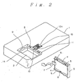
- Figure 2 is a perspective view showing the cover removed from the electronic appliance housing according to one embodiment of the present invention. Also, a radio paging receiver is employed as an example of this electronic appliance in this embodiment.
- a rectangular opening 1a is formed in a rear surface of the housing 1 of this radio paging receiver.
- a battery storage chamber 2 is defined within the housing 1.
- a cover 3 used to close this opening 1a is formed in a rectangular shape whose one end portion is bent, and a rib 4 is formed in a standing condition along both side edge portions thereof.
- Engage pieces 5 are fabricated on the ribs 4 and project outwardly on both sides.
- a locking groove 6 is formed in a portion of one rib 4. Further, another engage piece 7 whose tip portion is wedge-shaped is formed on the other end portion of the cover 3.
- the locking groove 6 is made of a notch having the shape of a parallelogram (as will be discussed later).
- engage projection portions 8 engaged with the engage piece 5 of the cover 3 are provided at both sides of the opening 1a of the housing 1.
- An engage hole 9 is made in an end face of the opening 1a.
- a slide portion 10 constructed of a rectangular concave portion is formed in one side of the opening 1a along a direction perpendicular to this side surface.
- a locking piece 11 is slidably provided within this slide portion 10 for movement along the same direction as the above-described direction.
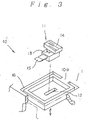
- FIG 3 is a fragmentary perspective view showing the detailed structure of the slide portion 10, a portion of which is broken away.
- a slit 12 is opened along the slide direction in a bottom surface of the slide portion 10 formed in the housing 1.
- the locking piece 11 has a small piece portion 13 which penetrates through this slit 12, an operation portion 14 integrally formed on the upper portion thereof, and a locking portion 15 integrally formed on the lower portion thereof.
- the sectional shape of the locking portion 15 is made as a parallelogram corresponding to the above-described locking groove 6. It should be understood that although the parallelogram-shaped portion is formed as a complete notch groove in this embodiment, this parallelogram-shaped portion can form only a partial groove so long as an inclined portion is provided (the notch need not extend through the whole thickness of the rib 4).
- the slide portion 10 formed in the housing 1 has a notch slit 16 formed along both sides of this slide portion 10.
- the slide portion 10 is supported at one edge portion 10a with respect to the rest of the housing 1. While this supported edge portion 10a is used as a fulcrum, elastic deformation can be achieved along the thickness direction of the housing 1, namely, the upper/lower direction of Figure 3.
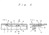
- the locking piece 11 can be slid from the opening 1a to the withdrawn position in a similar manner to the known structure. Then, while the cover 3 is slid with respect to the opening 1a by utilizing the rib 4 of the cover 3, the cover 3 is inserted. As a result, as illustrated in Figure 4, the engaging piece 5 is engaged with the engaging projection portion 8, and also the engaging piece 7 is engaged with the engaging hole 9. Then the locking piece 11 is slid toward the opening 1a, the locking portion 15 is engaged into the locking groove 6, and the cover 3 is brought into the fixed condition with respect to the housing 1, so that it is possible to avoid the cover 3 from falling off the opening 1a.
- the cover 3 when the cover 3 is to be removed from the opening 1a, the locking piece 11 is moved in the direction away from the opening 1a, so that the locking portion 15 is withdrawn from the locking groove 6.
- the cover 3 can be removed from the opening 1a by performing a similar operation to the known manner.
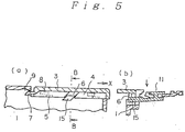
- the locking condition may be released by depressing the locking piece 11 downwardly while the locking portion 15 still engages the locking groove 6.
- the slide portion 10 for supporting the locking piece 11 is elastically deformed downwardly, with one edge portion 10a thereof being used as a fulcrum.
- both the slide portion 10 and the locking piece 11 are elastically deformed downwardly as an integral unit, the inclined edge portions of the locking portion 15 and the locking groove 6, which are in the form of parallelograms, are brought into an abutting condition.
- both of the locking piece 11 and the operation portion 14 can be made compact because of the arranging space relationship in the housing 1.
- the sliding operation of the locking piece 11 is no longer necessary when the locking condition is to be released, in which the operation was difficult. Rather, the locking condition can be released only by merely depressing the locking piece 11, resulting in very easy operation.
- Figure 7 is a perspective view showing the cover removed in the electronic appliance housing according to another embodiment of the present invention.
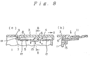
- Figure 8 shows at (a) a cross-sectional view representing such a condition that a lock releasing operation by a locking piece is accomplished and at (b) a sectional view thereof, taken along a line C-C of (a).
- the structure shown in Figure 7 is substantially identical to the above-explained structure indicated in Figure 2. A difference between them is that, in the structure shown in Figure 7, a spring 17 used to push the cover upwardly is provided in a bottom portion 19 of the housing to which the cover is mounted. In this case, as one example of the spring 17, there is shown a leaf spring embedded in the bottom of the housing.
- the spring 17 When the cover 3 is to be mounted on the housing 1 by the sliding operation, the spring 17 is depressed downwardly. Once the cover 3 is mounted on the housing 1, a pawl 18 of the engaging piece 7 of the cover 3 enters into the engaging hole 9 of the housing 1, so that the cover 3 is retained. Since the cover 3 is pushed upwardly by the spring 17, the upper surface of the engaging piece 5 of the cover 3 is strongly in contact with the lower surface of the engaging projection portion 8 of the housing 1. With this contact, even when the housing 1 is vibrated, there is no possibility that the cover 3 would be vibrated.
- the cover Since the spring is employed so as to push up the cover to the housing side, the cover is not easily removed from the housing, but also is not swung even under vibrations. Even if such a structure is employed, the cover can when desired be simply released from the housing by depressing the operation portion.
- the present invention is not limited to these embodiments, but may be similarly applied to a portable transceivers or telephones, and other electronic appliances. Also, in these embodiments, the present invention can be applied to battery covers. Alternatively, the present invention may be similarly applied to such a cover structure for closing an opening which is used to store an attachment part in the housing.
- the edge portions inclined along the cover sliding direction are formed in the locking portion and on the locking piece for bringing the cover into the locking condition, and also engaging the locking portion into the locking groove.
- the locking piece is supported in such a manner that this locking piece can be slid on a portion of the housing, and this portion of the housing may be elastically deformed in combination with the locking piece along the plate thickness direction of the housing by way of the slit formed around this portion.
- the locking piece may be elastically deformed toward the inside of the housing.
- both of the locking piece and a portion of the housing are elastically deformed by a preselected amount, it is so constructed that the locking portion is released from the notch edge of the locking groove and moves outside this locking groove. Therefore, when the locking piece is elastically deformed by a preselected amount, the engaging condition between the locking portion and the locking groove is released, without sliding the locking piece, so that the cover may be removed.
Applications Claiming Priority (2)
| Application Number | Priority Date | Filing Date | Title |
|---|---|---|---|
| JP6319406A JP2674537B2 (ja) | 1994-11-30 | 1994-11-30 | 電子機器筐体 |
| JP319406/94 | 1994-11-30 |
Publications (2)
| Publication Number | Publication Date |
|---|---|
| EP0716461A1 true EP0716461A1 (de) | 1996-06-12 |
| EP0716461B1 EP0716461B1 (de) | 1998-03-11 |
Family
ID=18109838
Family Applications (1)
| Application Number | Title | Priority Date | Filing Date |
|---|---|---|---|
| EP95308592A Expired - Lifetime EP0716461B1 (de) | 1994-11-30 | 1995-11-29 | Elektronisches Apparatgehäuse mit Speicherabschnitt |
Country Status (6)
| Country | Link |
|---|---|
| US (1) | US5793619A (de) |
| EP (1) | EP0716461B1 (de) |
| JP (1) | JP2674537B2 (de) |
| AU (1) | AU700510B2 (de) |
| CA (1) | CA2163604C (de) |
| DE (1) | DE69501774T2 (de) |
Cited By (7)
| Publication number | Priority date | Publication date | Assignee | Title |
|---|---|---|---|---|
| GB2315936A (en) * | 1996-07-31 | 1998-02-11 | Nec Corp | Battery cover lock with integral battery removing device |
| US5722705A (en) * | 1995-06-24 | 1998-03-03 | Nec Corporation | Lock structure for cover of electronic appliance |
| EP0903793A1 (de) * | 1997-09-19 | 1999-03-24 | Smoby | Batteriegehäuse für Spielzeug und Spielzeug mit einem solchen Gehäuse |
| WO2005060116A2 (en) * | 2003-12-18 | 2005-06-30 | Thomson Licensing | Housing assembly for an electronic device |
| EP1858233A1 (de) * | 2006-05-16 | 2007-11-21 | Lg Electronics Inc. | Verschlussanordnung für eine Batterieeinheit eines Mobiltelefons, und Mobiltelefon |
| EP1973181A1 (de) * | 2006-01-12 | 2008-09-24 | Max Co., Ltd. | Batteriepack mit verriegelungsmechanismus |
| WO2010141087A2 (en) * | 2009-06-05 | 2010-12-09 | S. C. Johnson & Son, Inc. | Toilet bowl cleaning and/or deodorizing device |
Families Citing this family (15)
| Publication number | Priority date | Publication date | Assignee | Title |
|---|---|---|---|---|
| US5931513A (en) * | 1997-10-20 | 1999-08-03 | Motorola | Housing assembly including a latch mechanism and a selective call receiver |
| JP2001119457A (ja) * | 1999-10-15 | 2001-04-27 | Matsushita Electric Ind Co Ltd | 携帯電話装置 |
| EP1463275B1 (de) * | 2003-03-25 | 2008-05-07 | LG Electronics Inc. | Verriegelungsmechanismus |
| JP4306571B2 (ja) * | 2004-09-15 | 2009-08-05 | 日本電気株式会社 | 電子機器、カバー及びケース |
| JP4790440B2 (ja) * | 2006-02-10 | 2011-10-12 | シャープ株式会社 | 電子機器 |
| US20070296225A1 (en) * | 2006-05-31 | 2007-12-27 | Motorola, Inc. | Locking mechanism for a communicatiion device |
| JP5444741B2 (ja) * | 2008-03-03 | 2014-03-19 | パナソニック株式会社 | 電子機器 |
| CN101593897B (zh) * | 2008-05-30 | 2012-03-14 | 深圳富泰宏精密工业有限公司 | 连接器盖体结构及具该盖体结构的电子装置 |
| CN101640988B (zh) * | 2008-07-30 | 2013-03-13 | 深圳富泰宏精密工业有限公司 | 电子装置的壳体 |
| JP5141583B2 (ja) * | 2009-02-12 | 2013-02-13 | 富士通モバイルコミュニケーションズ株式会社 | 電子機器 |
| TW201137681A (en) * | 2010-04-28 | 2011-11-01 | Giga Byte Tech Co Ltd | Mouse |
| CN102376912B (zh) * | 2010-08-11 | 2013-09-25 | 深圳富泰宏精密工业有限公司 | 电池盖锁持结构 |
| TWI462025B (zh) * | 2011-11-30 | 2014-11-21 | Wistron Corp | 具有可動式插卡結構之卡讀取器及電子裝置 |
| JP6036325B2 (ja) * | 2013-01-22 | 2016-11-30 | カシオ計算機株式会社 | 蓋の開閉構造、及び電子機器 |
| US10653220B2 (en) * | 2017-09-06 | 2020-05-19 | Fidlco, LLC | Modular mobile device case and related accessories |
Citations (2)
| Publication number | Priority date | Publication date | Assignee | Title |
|---|---|---|---|---|
| JPH01260757A (ja) | 1988-04-11 | 1989-10-18 | Matsushita Electric Ind Co Ltd | 電池収納装置 |
| EP0367608A1 (de) * | 1988-11-04 | 1990-05-09 | Motorola, Inc. | Batteriegehäuse mit integrierter Verriegelung und positiven Verschiebeelementen |
Family Cites Families (2)
| Publication number | Priority date | Publication date | Assignee | Title |
|---|---|---|---|---|
| JP2589088Y2 (ja) * | 1991-01-30 | 1999-01-20 | 日本電気株式会社 | つまみ保持構造 |
| US5578794A (en) * | 1995-01-05 | 1996-11-26 | Fluke Corporation | Cover assembly for restraining an object in an enclosure |
-
1994
- 1994-11-30 JP JP6319406A patent/JP2674537B2/ja not_active Expired - Fee Related
-
1995
- 1995-11-23 CA CA002163604A patent/CA2163604C/en not_active Expired - Fee Related
- 1995-11-28 US US08/562,218 patent/US5793619A/en not_active Expired - Fee Related
- 1995-11-29 AU AU39141/95A patent/AU700510B2/en not_active Ceased
- 1995-11-29 DE DE69501774T patent/DE69501774T2/de not_active Expired - Fee Related
- 1995-11-29 EP EP95308592A patent/EP0716461B1/de not_active Expired - Lifetime
Patent Citations (2)
| Publication number | Priority date | Publication date | Assignee | Title |
|---|---|---|---|---|
| JPH01260757A (ja) | 1988-04-11 | 1989-10-18 | Matsushita Electric Ind Co Ltd | 電池収納装置 |
| EP0367608A1 (de) * | 1988-11-04 | 1990-05-09 | Motorola, Inc. | Batteriegehäuse mit integrierter Verriegelung und positiven Verschiebeelementen |
Cited By (15)
| Publication number | Priority date | Publication date | Assignee | Title |
|---|---|---|---|---|
| GB2302611B (en) * | 1995-06-24 | 1998-05-13 | Nec Corp | Lock structure for cover of electronic appliance |
| US5722705A (en) * | 1995-06-24 | 1998-03-03 | Nec Corporation | Lock structure for cover of electronic appliance |
| GB2315936B (en) * | 1996-07-31 | 2000-09-06 | Nec Corp | Battery storage structure for electronic equipment |
| US5882816A (en) * | 1996-07-31 | 1999-03-16 | Nec Corporation | Structure of battery storage portion for electronic equipment |
| GB2315936A (en) * | 1996-07-31 | 1998-02-11 | Nec Corp | Battery cover lock with integral battery removing device |
| EP0903793A1 (de) * | 1997-09-19 | 1999-03-24 | Smoby | Batteriegehäuse für Spielzeug und Spielzeug mit einem solchen Gehäuse |
| FR2768861A1 (fr) * | 1997-09-19 | 1999-03-26 | Smoby | Boitier a piles pour jouet, et jouet equipe d'un tel boitier |
| WO2005060116A2 (en) * | 2003-12-18 | 2005-06-30 | Thomson Licensing | Housing assembly for an electronic device |
| WO2005060116A3 (en) * | 2003-12-18 | 2008-01-03 | Thomson Licensing | Housing assembly for an electronic device |
| EP1973181A1 (de) * | 2006-01-12 | 2008-09-24 | Max Co., Ltd. | Batteriepack mit verriegelungsmechanismus |
| EP1973181A4 (de) * | 2006-01-12 | 2009-01-28 | Max Co Ltd | Batteriepack mit verriegelungsmechanismus |
| US7858219B2 (en) | 2006-01-12 | 2010-12-28 | Max Co., Ltd. | Locking mechanism of battery pack |
| EP1858233A1 (de) * | 2006-05-16 | 2007-11-21 | Lg Electronics Inc. | Verschlussanordnung für eine Batterieeinheit eines Mobiltelefons, und Mobiltelefon |
| WO2010141087A2 (en) * | 2009-06-05 | 2010-12-09 | S. C. Johnson & Son, Inc. | Toilet bowl cleaning and/or deodorizing device |
| WO2010141087A3 (en) * | 2009-06-05 | 2011-02-17 | S. C. Johnson & Son, Inc. | Toilet bowl cleaning and/or deodorizing device |
Also Published As
| Publication number | Publication date |
|---|---|
| AU3914195A (en) | 1996-06-06 |
| DE69501774D1 (de) | 1998-04-16 |
| EP0716461B1 (de) | 1998-03-11 |
| CA2163604C (en) | 1999-11-02 |
| US5793619A (en) | 1998-08-11 |
| DE69501774T2 (de) | 1998-07-09 |
| AU700510B2 (en) | 1999-01-07 |
| JPH08162079A (ja) | 1996-06-21 |
| JP2674537B2 (ja) | 1997-11-12 |
| CA2163604A1 (en) | 1996-05-31 |
Similar Documents
| Publication | Publication Date | Title |
|---|---|---|
| EP0716461B1 (de) | Elektronisches Apparatgehäuse mit Speicherabschnitt | |
| EP0367608B1 (de) | Batteriegehäuse mit integrierter Verriegelung und positiven Verschiebeelementen | |
| US7970441B2 (en) | Battery and battery locking unit of mobile terminal | |
| US20060115715A1 (en) | Battery cover fixing mechanism and battery cover and housing assembly | |
| US20100086840A1 (en) | Battery latching mechanism | |
| EP0635963A2 (de) | Tragbares Telefongerät zum Gebrauch mit einer Chipkarte | |
| JP2806900B2 (ja) | 電子機器の電池収納構造 | |
| US6547347B2 (en) | Device unit housing apparatus | |
| WO2003026040A1 (en) | Portable electronic equipment and battery mounting device of the equipment | |
| US4609119A (en) | Retaining device for mounting electrical units | |
| US20060019530A1 (en) | Battery pack locking apparatus for portable terminal | |
| US5803323A (en) | Structure of carrying case for electronic equipment | |
| JP3088349B2 (ja) | バッテリ固定構造 | |
| JP3704566B2 (ja) | 乾電池ケース | |
| JP3295637B2 (ja) | ボタン電池の保持構造 | |
| JPH05344042A (ja) | 携帯用電話機の電池パック固定装置 | |
| JP5167859B2 (ja) | 電子機器 | |
| JP3990750B2 (ja) | 乾電池ケース | |
| JPH07335187A (ja) | バッテリーパック装着機構 | |
| KR100661570B1 (ko) | 휴대폰의 배터리 잠금장치 | |
| JPH0765807A (ja) | 電池交換機構 | |
| JPH09204909A (ja) | バッテリケース脱着機構 | |
| JP3990748B2 (ja) | 乾電池ケース | |
| JP3529913B2 (ja) | 携帯機器における電池ロック構造 | |
| JPH0945170A (ja) | 操作ボタン装置 |
Legal Events
| Date | Code | Title | Description |
|---|---|---|---|
| PUAI | Public reference made under article 153(3) epc to a published international application that has entered the european phase |
Free format text: ORIGINAL CODE: 0009012 |
|
| AK | Designated contracting states |
Kind code of ref document: A1 Designated state(s): DE GB |
|
| 17P | Request for examination filed |
Effective date: 19960423 |
|
| GRAG | Despatch of communication of intention to grant |
Free format text: ORIGINAL CODE: EPIDOS AGRA |
|
| GRAH | Despatch of communication of intention to grant a patent |
Free format text: ORIGINAL CODE: EPIDOS IGRA |
|
| 17Q | First examination report despatched |
Effective date: 19970319 |
|
| GRAH | Despatch of communication of intention to grant a patent |
Free format text: ORIGINAL CODE: EPIDOS IGRA |
|
| GRAA | (expected) grant |
Free format text: ORIGINAL CODE: 0009210 |
|
| AK | Designated contracting states |
Kind code of ref document: B1 Designated state(s): DE GB |
|
| REF | Corresponds to: |
Ref document number: 69501774 Country of ref document: DE Date of ref document: 19980416 |
|
| PLBE | No opposition filed within time limit |
Free format text: ORIGINAL CODE: 0009261 |
|
| STAA | Information on the status of an ep patent application or granted ep patent |
Free format text: STATUS: NO OPPOSITION FILED WITHIN TIME LIMIT |
|
| 26N | No opposition filed | ||
| REG | Reference to a national code |
Ref country code: GB Ref legal event code: IF02 |
|
| PGFP | Annual fee paid to national office [announced via postgrant information from national office to epo] |
Ref country code: GB Payment date: 20031126 Year of fee payment: 9 |
|
| PGFP | Annual fee paid to national office [announced via postgrant information from national office to epo] |
Ref country code: DE Payment date: 20031211 Year of fee payment: 9 |
|
| PG25 | Lapsed in a contracting state [announced via postgrant information from national office to epo] |
Ref country code: GB Free format text: LAPSE BECAUSE OF NON-PAYMENT OF DUE FEES Effective date: 20041129 |
|
| PG25 | Lapsed in a contracting state [announced via postgrant information from national office to epo] |
Ref country code: DE Free format text: LAPSE BECAUSE OF NON-PAYMENT OF DUE FEES Effective date: 20050601 |
|
| GBPC | Gb: european patent ceased through non-payment of renewal fee |
Effective date: 20041129 |