EP0711633B1 - Verfahren und Bearbeitungsmaschine zum Strahlschneiden von Werkstücken mittels eines Schneidstrahls - Google Patents
Verfahren und Bearbeitungsmaschine zum Strahlschneiden von Werkstücken mittels eines Schneidstrahls Download PDFInfo
- Publication number
- EP0711633B1 EP0711633B1 EP95115843A EP95115843A EP0711633B1 EP 0711633 B1 EP0711633 B1 EP 0711633B1 EP 95115843 A EP95115843 A EP 95115843A EP 95115843 A EP95115843 A EP 95115843A EP 0711633 B1 EP0711633 B1 EP 0711633B1
- Authority
- EP
- European Patent Office
- Prior art keywords
- cutting
- workpiece
- jet
- units
- jets
- Prior art date
- Legal status (The legal status is an assumption and is not a legal conclusion. Google has not performed a legal analysis and makes no representation as to the accuracy of the status listed.)
- Expired - Lifetime
Links
- 238000005520 cutting process Methods 0.000 title claims description 290
- 238000000034 method Methods 0.000 title claims description 28
- 239000012530 fluid Substances 0.000 title description 2
- XLYOFNOQVPJJNP-UHFFFAOYSA-N water Substances O XLYOFNOQVPJJNP-UHFFFAOYSA-N 0.000 claims description 14
- 230000001419 dependent effect Effects 0.000 claims 1
- 239000002184 metal Substances 0.000 description 11
- 238000003754 machining Methods 0.000 description 5
- 230000000694 effects Effects 0.000 description 3
- 239000003082 abrasive agent Substances 0.000 description 2
- 239000000463 material Substances 0.000 description 2
- 238000000926 separation method Methods 0.000 description 2
- 230000006978 adaptation Effects 0.000 description 1
- 230000006735 deficit Effects 0.000 description 1
- 230000002787 reinforcement Effects 0.000 description 1
Images
Classifications
-
- B—PERFORMING OPERATIONS; TRANSPORTING
- B24—GRINDING; POLISHING
- B24C—ABRASIVE OR RELATED BLASTING WITH PARTICULATE MATERIAL
- B24C3/00—Abrasive blasting machines or devices; Plants
- B24C3/02—Abrasive blasting machines or devices; Plants characterised by the arrangement of the component assemblies with respect to each other
- B24C3/04—Abrasive blasting machines or devices; Plants characterised by the arrangement of the component assemblies with respect to each other stationary
-
- B—PERFORMING OPERATIONS; TRANSPORTING
- B24—GRINDING; POLISHING
- B24C—ABRASIVE OR RELATED BLASTING WITH PARTICULATE MATERIAL
- B24C1/00—Methods for use of abrasive blasting for producing particular effects; Use of auxiliary equipment in connection with such methods
- B24C1/04—Methods for use of abrasive blasting for producing particular effects; Use of auxiliary equipment in connection with such methods for treating only selected parts of a surface, e.g. for carving stone or glass
- B24C1/045—Methods for use of abrasive blasting for producing particular effects; Use of auxiliary equipment in connection with such methods for treating only selected parts of a surface, e.g. for carving stone or glass for cutting
-
- B—PERFORMING OPERATIONS; TRANSPORTING
- B24—GRINDING; POLISHING
- B24C—ABRASIVE OR RELATED BLASTING WITH PARTICULATE MATERIAL
- B24C3/00—Abrasive blasting machines or devices; Plants
- B24C3/02—Abrasive blasting machines or devices; Plants characterised by the arrangement of the component assemblies with respect to each other
-
- B—PERFORMING OPERATIONS; TRANSPORTING
- B26—HAND CUTTING TOOLS; CUTTING; SEVERING
- B26F—PERFORATING; PUNCHING; CUTTING-OUT; STAMPING-OUT; SEVERING BY MEANS OTHER THAN CUTTING
- B26F3/00—Severing by means other than cutting; Apparatus therefor
- B26F3/004—Severing by means other than cutting; Apparatus therefor by means of a fluid jet
-
- Y—GENERAL TAGGING OF NEW TECHNOLOGICAL DEVELOPMENTS; GENERAL TAGGING OF CROSS-SECTIONAL TECHNOLOGIES SPANNING OVER SEVERAL SECTIONS OF THE IPC; TECHNICAL SUBJECTS COVERED BY FORMER USPC CROSS-REFERENCE ART COLLECTIONS [XRACs] AND DIGESTS
- Y10—TECHNICAL SUBJECTS COVERED BY FORMER USPC
- Y10T—TECHNICAL SUBJECTS COVERED BY FORMER US CLASSIFICATION
- Y10T83/00—Cutting
- Y10T83/364—By fluid blast and/or suction
Definitions
- the invention relates to a method for jet cutting Workpieces according to the preamble of claim 1.
- the invention further relates to a processing machine for performing such Method according to the preamble of claim 9.
- EP 0 207 069 A1 discloses a method and an apparatus for cutting workpieces using two cutting beams, the opposite sides of the to be machined Workpiece to be aimed at this and approximately in the middle of the material meet each other.
- the invention is based on the object, the known methods for jet cutting workpieces and the known ones To further develop processing machines. It should be a good one Quality of the cut edges even at high cutting speeds let achieve.
- the process-related task mentioned is according to the invention solved in that within the scope of a method of the initially mentioned Type the cutting beams in such a way to the one to be processed Workpiece that the beam axes are below cut the workpiece and that the beam axes are immediately adjacent to each other on the cutting line run.
- the section plane is formed by the tangential plane to the workpiece in the respective machining point.
- a conceptual model to explain the observed Phenomenon assumes that the inventive Use of two cutting beams running at an angle to each other one cutting beam supports the other and thereby the Cutting effect of at least one of the cutting beams is enhanced is caused by a lateral breakout due to the support effect of the cutting beam in question compared to the one to be processed Workpiece is prevented.
- An "immediately adjacent" arrangement the cutting rays are then within the meaning of the invention before when the distance of the points of incidence of the cutting beams the cutting line is so low that the reinforcement described the cutting action of at least one of the cutting beams is achieved.
- machining results can be achieved that a first cutting beam is substantially perpendicular and a second cutting beam at a right angle deviating angle is directed at the workpiece.
- a second cutting beam at a right angle deviating angle is directed at the workpiece.
- two cutting beams under one of one right angle deviating angle directed at the workpiece become.
- Another process variant is characterized in that two cutting beams are directed onto the workpiece in such a way that the beam axes form an angle of less than 60 °.
- the advantages of the method according to the invention can be with cutting jets from different cutting media to reach.
- the process uses cutting jets in the form of preferably abrasive agents leading pressurized water jets aimed at the workpiece.
- the pressurized water jets are expediently under a pressure of 2800 bar to 3400 bar aimed at the workpiece.
- a preferred version of the method according to the invention draws is characterized in that only for cutting the workpiece a cutting beam and after cutting the workpiece Another cutting beam is aimed at the workpiece.
- the device-related task mentioned at the outset becomes solved the invention in that on generic processing machines the cutting units simultaneously in the cutting operation and the workpiece can be moved relative to one another along a common cutting line of the cutting units, the cutting units being arranged and aligned in this way are that the cutting beams span a cutting beam plane running in the cutting direction, that the beam axes of the cutting beams cut underneath the workpiece and that the beam axes are directly at the intersection run adjacent.
- the processing machine provided that at least one cutting unit around a substantially parallel to the cutting plane running pivot axis opposite the assigned cutting unit pivotable and in the respective Swivel position is definable. Leave on such a processing machine the cutting beams are parallel to each other or under variable Align angles to each other. Accordingly, the Processing machine flexible to different application requirements be adjusted.
- a version of the processing machine according to the invention offers where the cutting units essentially parallel to the cutting plane in the cutting direction, are slidably mounted relative to each other.
- the cutting beams expediently take in the cutting operation a certain position in relation to the cutting direction. there the position of the cutting beams in relation to the cutting direction defined by the course of the cutting rays spanned cutting beam plane opposite the cutting direction. If the cutting direction is now to be changed, the position is to maintain the cutting beams in relation to the changed cutting direction. To this The purpose is to shift the cutting beam plane relative to the workpiece. Such a shift in the cutting beam plane is at a preferred embodiment of the processing machine according to the invention thereby allowing at least one cutting unit around a substantially perpendicular to the cutting plane Rotation-swivel axis rotatable relative to the workpiece is.
- a change in the cutting direction and a related one Rotary pivoting movement of at least one cutting unit can both in the current cutting operation and after completion of a separating cut.
- the former In this case there is a curved cut, in the second Fall can be based on the finished separation cut and another separation cut running at an angle to it become.
- a compact processing machine results when the cutting units on a common cutting head of the processing machine are provided.
- a preferred embodiment of the processing machine according to the invention on the pressurized water units as cutting units are provided, characterized in that for each jet of pressurized water an abrasive supply is provided. Thereby the cutting beams can be independent in their cutting behavior modify each other.
- the cutting units as provided in a development of the invention, separately with the assigned source for the cutting beam are connectable.
- the cutting units can be phase of the cutting process operate together or individually.
- a prerequisite for automated workpiece processing is created in that the cutting units by means of a Connection control controlled with the assigned source for the Cutting beam can be connected.
- Processing machines according to the invention their cutting units separately and / or controlled by means of a connection control the associated source for the cutting beam can be connected, are also used, for example, to implement that variant of the used method according to the invention, in which the to be processed Cut the workpiece with just one cutting beam and then further processed with two cutting beams.
- Another preferred embodiment of an inventive Processing machine with a speed control for Control of the relative speed between the cutting units and the workpiece is characterized by that by means of the speed control, the relative speed between the cutting units and the workpiece on the number of a cutting beam on the workpiece directing cutting units and / or the duration of the connection the cutting units is controlled.
- Such a processing machine is also preferred for the one described above Two-phase cutting operation determined. In the cutting phase, in which only a cutting beam is aimed at the workpiece is a proportionate speed control low relative speed between that in the cutting operation located cutting unit and the workpiece.
- the processing machine according to the invention operates in this phase according to the conventional machining process, accordingly the separating cut produced by means of a single processing beam becomes.
- the cutting speed ie the relative speed between the cutting units and the workpiece not abruptly, but rather gradually increased as soon as the second cutting unit has reached the workpiece. This is accomplished by means of the speed control, which the relative speed between cutting units and workpiece after the second cutting unit takes effect and after increases.
- the speed control which the relative speed between cutting units and workpiece after the second cutting unit takes effect and after increases.
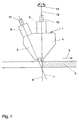
- the 1 shows a cutting head 1 of a water jet cutting machine, that in the direction of an arrow 2 relative to one stationary workpiece in the form of a sheet 3 is moved.
- the cutting head 1 is on the metal sheet 3 overlapping portal Carrier of a machine sled attached.
- the machine slide can be moved along the metal sheet 3.
- the cutting head 1 can be moved in the longitudinal direction of the carrier and thus in the transverse direction of the direction of travel of the machine slide move in a controlled manner. Accordingly, the Cutting head 1 reach every point in the sheet plane.
- Integrated in the cutting head 1 are two cutting units 4, 5, which the metal sheet 3 in the cutting operation with cutting beams 6, 7 act in the form of high pressure water jets, the Beam axes intersect below the cutting plane.
- the cutting unit 4 directs its cutting beam 6 under an im substantial right angle on the surface of the metal sheet 3.
- the cutting beam 7 emitted by the cutting unit 5 runs at an angle other than a right angle the workpiece surface.
- the cutting beams 6, 7 or their Beam axes span a perpendicular to the sheet 3 Cutting beam level.
- the cutting units are on the side facing away from the metal sheet 3 4, 5 via connections 8, 9 and high-pressure lines indicated in FIG. 1 10, 11 each connected to a high pressure pump.
- the entire cutting head 1 can in the direction of the beam axis of the cutting beam 6 rotating pivot axis 12 in Be pivoted in the direction of an arrow 13.
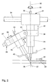
- the cutting machine partially shown in Figure 2 has one Cutting head 21 with two separate cutting units 24, 25.
- a carrier 34 of a machine slide Cutting head 21 in the direction of a symbolizing the cutting direction Arrow 22 opposite a workpiece in the form of a metal sheet 23 motor-driven movable.
- the Machine slide perpendicular to the drawing plane according to FIG. 2 be moved.
- the cutting units 24, 25 are substantially parallel to one another to the plane of the sheet 23, that is to say to the cutting plane, extending pivot axis 35 pivotally connected to each other.
- For Clamp-like brackets are used to produce the swivel connection 36, 37 which enclose the cutting units 24, 25.
- Means of a spindle drive 38 is the cutting unit 25 inside its holder 37 in the direction of a double arrow 39 deliverable.
- the cutting unit 25 can be in the direction of a double arrow 41 are moved, the bracket 36, which the Cuts around cutting unit 24, can in the direction of a double arrow 40 delivered substantially perpendicular to the plane of the sheet 23 become.
- the entire can be rotated about a pivot axis 32 Cutting head 21 in the direction of a double arrow 33 motorized swivel.
- the cutting units 24, 25 align in FIG. 2 only indicated cutting rays 26, 27 on the surface the sheet of metal 23.
- the cutting beam 26 runs Cutting unit 24 essentially perpendicular to the workpiece surface: the cutting beam 27 of the cutting unit 25 also includes the workpiece surface is different from a right angle Angle on.
- the two cutting beams 26, 27 intersect in the cutting plane and clamp one in the cutting direction, the is called the cutting beam plane extending in the direction of arrow 22 on.
- the cutting beams 26, 27 are generated by means of under pressure standing cutting water, which the cutting units 24, 25 over High pressure lines 30, 31 is supplied. To vary the The cutting beams 26, 27 can have a cutting action via feed lines 42, 43 with abrasive agents. It is for the Cutting jets 26, 27 each have their own abrasive supply intended. In this way, the cutting rays can be 26, 27 in their cutting behavior to the requirements adapt to the respective application.
- the adaptation to different operating conditions serve the adjustment options resulting from the above explanations the cutting units 24, 25 by pivoting the cutting unit 25 about the pivot axis 35 the one enclosed by the cutting beams 26, 27 or the beam axes Change angle.
- the location of the intersection the cutting beams 26, 27 based on the plane of the Sheet 23 can be varied.
- a delivery option for the Cutting unit 25 offers opposite the surface of the sheet 23 the adjustability of the cutting unit 25 in the direction of Double arrow 41.
- An adjustment of the cutting unit 25 in the direction the double arrow 39 is with an adjustment of the cutting unit 25 connected in the direction of the double arrow 41, if so the position of the intersection of the cutting beams 26, 27 and Stranlachsen changed compared to the sheet 23, the distance of the beam exit at the cutting unit 25 from the metal sheet 23 but should remain the same.
- the processing machine is correct in its basic mode of operation 2 with the one shown in FIG. 1 and above described embodiment match. Both processing machines are of course also for machining workpieces suitable with a curved workpiece surface.
Landscapes
- Engineering & Computer Science (AREA)
- Mechanical Engineering (AREA)
- Life Sciences & Earth Sciences (AREA)
- Forests & Forestry (AREA)
- Perforating, Stamping-Out Or Severing By Means Other Than Cutting (AREA)
- Laser Beam Processing (AREA)
Applications Claiming Priority (2)
| Application Number | Priority Date | Filing Date | Title |
|---|---|---|---|
| DE4440631A DE4440631C2 (de) | 1994-11-14 | 1994-11-14 | Verfahren und Bearbeitungsmaschine zum Strahlschneiden von Werkstücken mittels wenigstens zweier Schneidstrahlen |
| DE4440631 | 1994-11-14 |
Publications (3)
| Publication Number | Publication Date |
|---|---|
| EP0711633A2 EP0711633A2 (de) | 1996-05-15 |
| EP0711633A3 EP0711633A3 (OSRAM) | 1996-06-05 |
| EP0711633B1 true EP0711633B1 (de) | 2001-11-28 |
Family
ID=6533279
Family Applications (1)
| Application Number | Title | Priority Date | Filing Date |
|---|---|---|---|
| EP95115843A Expired - Lifetime EP0711633B1 (de) | 1994-11-14 | 1995-10-07 | Verfahren und Bearbeitungsmaschine zum Strahlschneiden von Werkstücken mittels eines Schneidstrahls |
Country Status (4)
| Country | Link |
|---|---|
| US (2) | US5605492A (OSRAM) |
| EP (1) | EP0711633B1 (OSRAM) |
| JP (1) | JPH08229900A (OSRAM) |
| DE (1) | DE4440631C2 (OSRAM) |
Families Citing this family (70)
| Publication number | Priority date | Publication date | Assignee | Title |
|---|---|---|---|---|
| US5782673A (en) * | 1996-08-27 | 1998-07-21 | Warehime; Kevin S. | Fluid jet cutting and shaping system and method of using |
| EP0863275A3 (en) * | 1997-03-07 | 1998-10-21 | JENOPTIK Aktiengesellschaft | Method and apparatus for removing wall joints |
| SG68035A1 (en) * | 1997-03-27 | 1999-10-19 | Canon Kk | Method and apparatus for separating composite member using fluid |
| NL1007589C1 (nl) * | 1997-11-20 | 1999-05-25 | Tno | Werkwijze en inrichting voor het bewerken van een werkstuk. |
| DE19754602C1 (de) * | 1997-12-10 | 1999-04-29 | Messer Griesheim Schweistechni | Einrichtung zum Entfernen einer Schicht, wie Primer von beschichteten Blechen sowie zum Markieren der Bleche |
| US6183348B1 (en) * | 1998-04-07 | 2001-02-06 | Bechtel Bwxt Idaho, Llc | Methods and apparatuses for cutting, abrading, and drilling |
| US6273790B1 (en) * | 1998-12-07 | 2001-08-14 | International Processing Systems, Inc. | Method and apparatus for removing coatings and oxides from substrates |
| US6217670B1 (en) | 1998-12-31 | 2001-04-17 | Cf Gomma Usa, Inc. | Method of manufacturing coated fluid tubing |
| US6126524A (en) * | 1999-07-14 | 2000-10-03 | Shepherd; John D. | Apparatus for rapid repetitive motion of an ultra high pressure liquid stream |
| FR2804895B1 (fr) * | 2000-02-10 | 2002-08-02 | France Etat | Dispositif de neutralisation d'engins explosifs par jet d'eau basse pression |
| US6615695B1 (en) * | 2000-06-27 | 2003-09-09 | Medtronic, Inc. | Alternative fabrication method for spiral electrodes |
| US6283832B1 (en) * | 2000-07-18 | 2001-09-04 | John D. Shepherd | Surface treatment method with rapid repetitive motion of an ultra high pressure liquid stream |
| FI112180B (fi) * | 2000-08-22 | 2003-11-14 | Upm Kymmene Corp | Menetelmä ja laite paperiradan reunan leikkaamiseksi |
| AU2001287127A1 (en) | 2000-09-07 | 2002-03-22 | Universal Leaf Tobacco Company, Inc. | Method and apparatus for cutting the tie-leaf on bundled leaf tobacco |
| US20020075597A1 (en) * | 2000-12-20 | 2002-06-20 | Seagate Technology Llc | Method and apparatus for folding thin flexible parts that are used in a disc drive |
| DE10113599A1 (de) * | 2001-03-20 | 2002-10-02 | Fisba Optik Ag St Gallen | Vorrichtung zur abrasiven Bearbeitung von Flächen von optischen Elementen |
| JP2002307312A (ja) * | 2001-04-11 | 2002-10-23 | Olympus Optical Co Ltd | 研磨加工装置、研磨加工方法、研磨加工をコンピュータに実行させる制御プログラムおよび記録媒体 |
| JP2003017667A (ja) | 2001-06-29 | 2003-01-17 | Canon Inc | 部材の分離方法及び分離装置 |
| JP2003017668A (ja) * | 2001-06-29 | 2003-01-17 | Canon Inc | 部材の分離方法及び分離装置 |
| US20030032369A1 (en) * | 2001-08-10 | 2003-02-13 | Carpenter Steven J. | Apparatus and process for surface treating interior of workpiece |
| US6766216B2 (en) * | 2001-08-27 | 2004-07-20 | Flow International Corporation | Method and system for automated software control of waterjet orientation parameters |
| JP2005500175A (ja) * | 2001-08-27 | 2005-01-06 | フロー インターナショナル コーポレイション | 高圧流体ジェットを発生するための装置 |
| US7464630B2 (en) * | 2001-08-27 | 2008-12-16 | Flow International Corporation | Apparatus for generating and manipulating a high-pressure fluid jet |
| US6769956B1 (en) * | 2002-02-04 | 2004-08-03 | Oberg Industries | Apparatus and method for rapid, precise positioning of a grit-blasting nozzle |
| US20030169460A1 (en) * | 2002-03-11 | 2003-09-11 | Siemens Technology-To-Business Center, Llc | On-demand service performance upgrade for wireless network |
| ITMI20021704A1 (it) * | 2002-07-30 | 2004-01-30 | Giovanni Gambini | Macchina per la troncatura multipla di rotoli di carta asciugatutto e/o igienica da log |
| US6705921B1 (en) | 2002-09-09 | 2004-03-16 | John D. Shepherd | Method and apparatus for controlling cutting tool edge cut taper |
| AT412197B (de) * | 2002-11-22 | 2004-11-25 | Lisec Peter | Vorrichtung zum bearbeiten von werkstoffplatten |
| DE10301772A1 (de) * | 2003-01-18 | 2004-07-29 | Voith Paper Patent Gmbh | Wasserstrahlschneideinrichtung |
| US7074112B2 (en) * | 2003-03-21 | 2006-07-11 | Omax Corporation | Apparatus that holds and tilts a tool |
| US8573901B2 (en) * | 2003-09-02 | 2013-11-05 | Kennametal Inc. | Assembly for rotating a cutting insert during a turning operation and inserts used therein |
| US7156006B2 (en) * | 2003-09-02 | 2007-01-02 | Kennametal Inc. | Method and assembly for rotating a cutting insert during a turning operation and inserts used therein |
| US6922605B1 (en) * | 2003-10-10 | 2005-07-26 | Omax Corporation | Automated fluid-jet tilt compensation for lag and taper |
| US20050087631A1 (en) * | 2003-10-28 | 2005-04-28 | Ursic Thomas A. | Intersecting jet - waterjet nozzle |
| US6988434B1 (en) * | 2003-12-03 | 2006-01-24 | Elk Premium Building Products, Inc. | Multi-axis tool positioner and related methods |
| NL1029171C2 (nl) * | 2005-06-02 | 2006-12-05 | Fico Bv | Inrichting en werkwijze voor het met een dubbele snijstraal bewerken van elektronische componenten. |
| US8540552B2 (en) * | 2007-04-24 | 2013-09-24 | Techni Waterjet Pty Ltd | Water jet cutting machine |
| US8308525B2 (en) * | 2008-11-17 | 2012-11-13 | Flow Internationl Corporation | Processes and apparatuses for enhanced cutting using blends of abrasive materials |
| EP2196285A1 (en) * | 2008-12-11 | 2010-06-16 | Nederlandse Organisatie voor toegepast-natuurwetenschappelijk Onderzoek TNO | Method and apparatus for polishing a workpiece surface |
| US20100180738A1 (en) * | 2009-01-22 | 2010-07-22 | Michael Tavger | Liquid cutting device |
| CH700798A1 (de) * | 2009-03-31 | 2010-10-15 | Bystronic Laser Ag | Vorrichtung und Verfahren zum Wasserstrahlschneiden. |
| IT1396287B1 (it) * | 2009-09-28 | 2012-11-16 | Biesse Spa | Distributore in continuo |
| US8821213B2 (en) * | 2010-10-07 | 2014-09-02 | Omax Corporation | Piercing and/or cutting devices for abrasive waterjet systems and associated systems and methods |
| US8895096B2 (en) | 2011-06-22 | 2014-11-25 | Frito-Lay North America, Inc. | Continuous oven with a cascading conveyor |
| US8506361B2 (en) * | 2011-08-25 | 2013-08-13 | General Electric Company | Fixture to facilitate sandblasting of a cylindrical object |
| US20150150269A1 (en) * | 2012-08-01 | 2015-06-04 | Frito-Lay North America, Inc. | Continuous process and apparatus for making a pita chip |
| US9586306B2 (en) | 2012-08-13 | 2017-03-07 | Omax Corporation | Method and apparatus for monitoring particle laden pneumatic abrasive flow in an abrasive fluid jet cutting system |
| US8904912B2 (en) | 2012-08-16 | 2014-12-09 | Omax Corporation | Control valves for waterjet systems and related devices, systems, and methods |
| WO2014089224A1 (en) * | 2012-12-04 | 2014-06-12 | Ikonics Corporation | Apparatus and methods for abrasive cutting, drilling, and forming |
| JP6058575B2 (ja) * | 2014-03-19 | 2017-01-11 | 株式会社スギノマシン | ウォータージェット切断方法及びウォータージェット切断装置 |
| US9446501B2 (en) * | 2014-12-31 | 2016-09-20 | Spirit Aerosystems, Inc. | Method and apparatus for abrasive stream perforation |
| US10391712B2 (en) * | 2016-02-18 | 2019-08-27 | Xerox Corporation | System and method for automated cleaning of parts produced by a three-dimensional object printer |
| US11577366B2 (en) | 2016-12-12 | 2023-02-14 | Omax Corporation | Recirculation of wet abrasive material in abrasive waterjet systems and related technology |
| CN107283524A (zh) * | 2017-07-21 | 2017-10-24 | 南京工程学院 | 环保汽车零件高压水切割机 |
| EP3657952B1 (en) * | 2017-07-25 | 2024-06-19 | Équipements Frontmatec Inc. | Cutting assembly for trimming pieces of meat, processing system including such a cutting assembly, and corresponding methods of operating and use associated thereto |
| US10850366B2 (en) * | 2017-12-15 | 2020-12-01 | Raytheon Technologies Corporation | Plasma assisted surface finishing apparatus and method |
| US11554461B1 (en) | 2018-02-13 | 2023-01-17 | Omax Corporation | Articulating apparatus of a waterjet system and related technology |
| US11224987B1 (en) | 2018-03-09 | 2022-01-18 | Omax Corporation | Abrasive-collecting container of a waterjet system and related technology |
| WO2021016701A1 (en) * | 2019-07-26 | 2021-02-04 | Équipements Frontmatec Inc. | Fluid jet cutting assembly and processing system including such a cutting assembly |
| US12350790B2 (en) | 2019-07-29 | 2025-07-08 | Hypertherm, Inc. | Measuring abrasive flow rates in a conduit |
| WO2021127253A1 (en) | 2019-12-18 | 2021-06-24 | Hypertherm, Inc. | Liquid jet cutting head sensor systems and methods |
| CN111267006B (zh) * | 2020-02-28 | 2020-11-20 | 中冶京诚工程技术有限公司 | 金属板带除鳞设备与方法及其使用的抛砂器 |
| EP4127527A1 (en) | 2020-03-24 | 2023-02-08 | Hypertherm, Inc. | High-pressure seal for a liquid jet cutting system |
| KR20230005840A (ko) | 2020-03-30 | 2023-01-10 | 하이퍼썸, 인크. | 다기능 접속 종방향 단부들을 갖는 액체 제트 펌프를 위한 실린더 |
| CN112536725A (zh) * | 2020-11-10 | 2021-03-23 | 深圳市德润水下工程有限公司 | 水刀组件 |
| WO2022123608A1 (en) * | 2020-12-11 | 2022-06-16 | Lambhusasund Ehf. | An apparatus for trimming and cutting food items |
| US12383941B2 (en) * | 2021-06-24 | 2025-08-12 | Path Environmental Technology, LLC | Apparatus for cleaning a surface with a liquid jet and related methods |
| CN113649952B (zh) * | 2021-07-22 | 2022-09-20 | 滨州学院 | 一种飞机蒙皮切割装置 |
| PL4245460T3 (pl) * | 2022-03-17 | 2025-09-08 | Uhde High Pressure Technologies Gmbh | Maszyna do obróbki, w szczególności maszyna do obróbki płyt oraz sposób działania maszyny do obróbki |
| CN116749277B (zh) * | 2023-07-26 | 2025-07-29 | 苏州润弘安创自动化科技有限公司 | 一种水刀去毛刺精密设备 |
Citations (1)
| Publication number | Priority date | Publication date | Assignee | Title |
|---|---|---|---|---|
| US5068513A (en) * | 1990-09-28 | 1991-11-26 | Beloit Corporation | Water jet slitter with laser finish and method |
Family Cites Families (19)
| Publication number | Priority date | Publication date | Assignee | Title |
|---|---|---|---|---|
| US2290979A (en) * | 1941-06-14 | 1942-07-28 | Hydro Blast Corp | Sandblasting device |
| US2387193A (en) * | 1944-07-03 | 1945-10-16 | Waitstill H Swenarton | Method of and apparatus for sandblasting of ships' hulls |
| DE961061C (de) * | 1952-10-01 | 1957-03-28 | Graf & Co Sueddeutsche Catgutf | Verfahren und Vorrichtung zum Glaetten von Faeden aus tierischen Rohstoffen, z.B. Catgutfaeden, Darmsaiten |
| US3746108A (en) * | 1971-02-25 | 1973-07-17 | G Hall | Focus nozzle directional bit |
| US3927150A (en) * | 1972-09-26 | 1975-12-16 | Ciba Geigy Corp | Bicyclic phosphorus compounds |
| US3858358A (en) * | 1973-01-02 | 1975-01-07 | American Aero Ind | High pressure liquid and abrasive cleaning apparatus |
| US3828478A (en) * | 1973-06-25 | 1974-08-13 | E Bemis | Fluid-jet-abrasive device and system |
| GB1481042A (en) * | 1974-06-05 | 1977-07-27 | Hart B | Guns for forming jets of particulate material |
| US4125969A (en) * | 1977-01-25 | 1978-11-21 | A. Long & Company Limited | Wet abrasion blasting |
| US4249956A (en) * | 1979-08-01 | 1981-02-10 | Hartman Charles N | Method of removing paint from a brick surface |
| DE3343611A1 (de) * | 1983-12-02 | 1985-06-13 | Woma-Apparatebau Wolfgang Maasberg & Co Gmbh, 4100 Duisburg | Verfahren und vorrichtung zur materialbehandlung mit einem hochdruckmittelstrahl |
| AT385710B (de) * | 1985-06-26 | 1988-05-10 | Ver Edelstahlwerke Ag | Verfahren und vorrichtung zum trennen bzw. schneiden von flaechigen werkstuecken aus, z.b. faserverstaerkten kunststoffen |
| DE3533644C1 (en) * | 1985-09-20 | 1987-03-26 | Duerkopp System Technik Gmbh | Method and device for cutting sheet-like material using a jet of fluid at a very high pressure |
| US4945688A (en) * | 1985-10-22 | 1990-08-07 | Electric Power Research Institute, Inc. | Nozzle for entraining abrasive granules within a high pressure fluid jet and process of using same |
| SU1433660A1 (ru) * | 1987-03-09 | 1988-10-30 | Киевский технологический институт легкой промышленности | Способ резани высокоскоростной струей жидкости |
| US4787178A (en) * | 1987-04-13 | 1988-11-29 | Creative Glassworks International, Inc. | Fluid-jet cutting apparatus |
| DE8710495U1 (de) * | 1987-07-31 | 1987-10-01 | G. Siempelkamp GmbH & Co.KG, 47803 Krefeld | Vorrichtung zum Formattrennen und Längsbesäumen einer Preßgutmatte |
| DE9103749U1 (de) * | 1991-03-27 | 1991-06-27 | J.M. Voith Gmbh, 7920 Heidenheim | Wasserstrahl-Schneideinrichtung |
| DE9411021U1 (de) * | 1994-07-04 | 1994-09-15 | Sächsische Werkzeug und Sondermaschinen GmbH, 01904 Neukirch | Mehrkopfwasserstrahlschneidmaschine |
-
1994
- 1994-11-14 DE DE4440631A patent/DE4440631C2/de not_active Expired - Fee Related
-
1995
- 1995-10-07 EP EP95115843A patent/EP0711633B1/de not_active Expired - Lifetime
- 1995-11-10 JP JP7292773A patent/JPH08229900A/ja active Pending
- 1995-11-14 US US08/558,610 patent/US5605492A/en not_active Expired - Fee Related
-
1996
- 1996-12-09 US US08/762,543 patent/US5759086A/en not_active Expired - Fee Related
Patent Citations (1)
| Publication number | Priority date | Publication date | Assignee | Title |
|---|---|---|---|---|
| US5068513A (en) * | 1990-09-28 | 1991-11-26 | Beloit Corporation | Water jet slitter with laser finish and method |
Also Published As
| Publication number | Publication date |
|---|---|
| US5605492A (en) | 1997-02-25 |
| DE4440631C2 (de) | 1998-07-09 |
| EP0711633A2 (de) | 1996-05-15 |
| DE4440631A1 (de) | 1996-05-15 |
| EP0711633A3 (OSRAM) | 1996-06-05 |
| US5759086A (en) | 1998-06-02 |
| JPH08229900A (ja) | 1996-09-10 |
Similar Documents
| Publication | Publication Date | Title |
|---|---|---|
| EP0711633B1 (de) | Verfahren und Bearbeitungsmaschine zum Strahlschneiden von Werkstücken mittels eines Schneidstrahls | |
| DE4101749C2 (OSRAM) | ||
| DE3110235C2 (OSRAM) | ||
| DE10042197B4 (de) | Laser-Streckzieh-Bearbeitungseinrichtung für Blechteile und Verfahren | |
| EP2691206B1 (de) | Verfahren zur laserstrahlbearbeitung eines werkstücks | |
| DE102005027800A1 (de) | Vorrichtung zum mehrfachen Trennen eines flachen Werkstückes aus einem spröden Material mittels Laser | |
| DE202004004480U1 (de) | Kegelrad-Verzahnmaschine zum Anfasen und/oder Entgraten von Kanten an den Zähnen eines Kegelrades | |
| DE19853366B4 (de) | Vorrichtung und Verfahren zum Umformen | |
| DE2943228C2 (OSRAM) | ||
| WO2020120047A1 (de) | Rohrbearbeitungsmaschine zum schneiden von rohren oder profilen mittels eines laserstrahls | |
| DE9414501U1 (de) | Bearbeitungsmaschine mit relativverschiebbaren Drehvorrichtungen | |
| EP0585715B1 (de) | Elektroerosions-Schneidvorrichtung, Elektroerosions-Schneidverfahren und Erodierdraht | |
| DE4219431A1 (de) | Vorrichtung zum maschinellen Ausklinken von Rohren | |
| EP0602308B1 (de) | Vorrichtung zur Bearbeitung der Kantenränder von fortlaufend bewegten plattenförmigen Werkstücken | |
| EP1485225B1 (de) | Verfahren und schweissvorrichtung zum konturschweissen | |
| DE3923356C1 (OSRAM) | ||
| CH714436B1 (de) | Verfahren zur Verzahnbearbeitung eines Werkstücks mit einem Werkzeug, wobei während der Verzahnbearbeitung mittels einer Kühlmitteldüse Kühlmittel auf das Werkzeug aufgebracht wird. | |
| CH640771A5 (de) | Verfahren zum durchtrennen von beschichtetem plattenmaterial sowie einrichtung zu seiner durchfuehrung. | |
| EP1743728A1 (de) | Bandschweissmaschine, insbesondere Laser-Bandschweissmaschine | |
| DE3631512A1 (de) | Verfahren und vorrichtung zur ausbildung eines abgerundeten schnittrandes beim schneiden von glasscheiben mit einem fliessfaehigen schneidstrahl | |
| DE2726382B2 (de) | Vorrichtung zum Bohren und Ausschneiden oder Fräsen eines Bauteiles aus einem plattenförmigen Werkstück aus Holz o.dgl | |
| DE3309424C2 (de) | Verfahren zum Schleifen eines konischen Nockens sowie Maschine zum Durchführen des Verfahrens | |
| DE10109117C1 (de) | Entgratvorrichtung für Kegelräder | |
| EP3829813B1 (de) | Vorrichtung und verfahren zum bearbeiten eines werkstücks, insbesondere eines mit schneiden besetzten werkstücks, mittels eines schleif- oder erodierwerkzeugs | |
| DE4134925C1 (en) | Gear wheel machining fixture - has two cutter spindles with cutter head moving at angles |
Legal Events
| Date | Code | Title | Description |
|---|---|---|---|
| PUAI | Public reference made under article 153(3) epc to a published international application that has entered the european phase |
Free format text: ORIGINAL CODE: 0009012 |
|
| PUAL | Search report despatched |
Free format text: ORIGINAL CODE: 0009013 |
|
| AK | Designated contracting states |
Kind code of ref document: A2 Designated state(s): CH FR GB IT LI |
|
| AK | Designated contracting states |
Kind code of ref document: A3 Designated state(s): CH FR GB IT LI |
|
| RHK1 | Main classification (correction) |
Ipc: B26F 3/00 |
|
| 17P | Request for examination filed |
Effective date: 19960913 |
|
| 17Q | First examination report despatched |
Effective date: 19981201 |
|
| GRAG | Despatch of communication of intention to grant |
Free format text: ORIGINAL CODE: EPIDOS AGRA |
|
| GRAG | Despatch of communication of intention to grant |
Free format text: ORIGINAL CODE: EPIDOS AGRA |
|
| GRAG | Despatch of communication of intention to grant |
Free format text: ORIGINAL CODE: EPIDOS AGRA |
|
| GRAH | Despatch of communication of intention to grant a patent |
Free format text: ORIGINAL CODE: EPIDOS IGRA |
|
| GRAH | Despatch of communication of intention to grant a patent |
Free format text: ORIGINAL CODE: EPIDOS IGRA |
|
| GRAA | (expected) grant |
Free format text: ORIGINAL CODE: 0009210 |
|
| AK | Designated contracting states |
Kind code of ref document: B1 Designated state(s): CH FR GB IT LI |
|
| REG | Reference to a national code |
Ref country code: CH Ref legal event code: EP |
|
| REG | Reference to a national code |
Ref country code: GB Ref legal event code: IF02 |
|
| GBT | Gb: translation of ep patent filed (gb section 77(6)(a)/1977) |
Effective date: 20020306 |
|
| ET | Fr: translation filed | ||
| PLBE | No opposition filed within time limit |
Free format text: ORIGINAL CODE: 0009261 |
|
| STAA | Information on the status of an ep patent application or granted ep patent |
Free format text: STATUS: NO OPPOSITION FILED WITHIN TIME LIMIT |
|
| 26N | No opposition filed | ||
| PGFP | Annual fee paid to national office [announced via postgrant information from national office to epo] |
Ref country code: FR Payment date: 20031021 Year of fee payment: 9 |
|
| PGFP | Annual fee paid to national office [announced via postgrant information from national office to epo] |
Ref country code: CH Payment date: 20031023 Year of fee payment: 9 |
|
| PGFP | Annual fee paid to national office [announced via postgrant information from national office to epo] |
Ref country code: GB Payment date: 20041001 Year of fee payment: 10 |
|
| PG25 | Lapsed in a contracting state [announced via postgrant information from national office to epo] |
Ref country code: LI Free format text: LAPSE BECAUSE OF NON-PAYMENT OF DUE FEES Effective date: 20041031 Ref country code: CH Free format text: LAPSE BECAUSE OF NON-PAYMENT OF DUE FEES Effective date: 20041031 |
|
| REG | Reference to a national code |
Ref country code: CH Ref legal event code: PL |
|
| PG25 | Lapsed in a contracting state [announced via postgrant information from national office to epo] |
Ref country code: FR Free format text: LAPSE BECAUSE OF NON-PAYMENT OF DUE FEES Effective date: 20050630 |
|
| REG | Reference to a national code |
Ref country code: FR Ref legal event code: ST |
|
| PG25 | Lapsed in a contracting state [announced via postgrant information from national office to epo] |
Ref country code: IT Free format text: LAPSE BECAUSE OF NON-PAYMENT OF DUE FEES Effective date: 20051007 Ref country code: GB Free format text: LAPSE BECAUSE OF NON-PAYMENT OF DUE FEES Effective date: 20051007 |
|
| GBPC | Gb: european patent ceased through non-payment of renewal fee |
Effective date: 20051007 |