EP0710554B1 - Aufhängung für eine dem Wechseln von Druckplatten dienenden Vorrichtung - Google Patents
Aufhängung für eine dem Wechseln von Druckplatten dienenden Vorrichtung Download PDFInfo
- Publication number
- EP0710554B1 EP0710554B1 EP95116383A EP95116383A EP0710554B1 EP 0710554 B1 EP0710554 B1 EP 0710554B1 EP 95116383 A EP95116383 A EP 95116383A EP 95116383 A EP95116383 A EP 95116383A EP 0710554 B1 EP0710554 B1 EP 0710554B1
- Authority
- EP
- European Patent Office
- Prior art keywords
- printing plate
- printing
- plate changer
- rails
- rail
- Prior art date
- Legal status (The legal status is an assumption and is not a legal conclusion. Google has not performed a legal analysis and makes no representation as to the accuracy of the status listed.)
- Expired - Lifetime
Links
- 238000007639 printing Methods 0.000 title claims abstract description 44
- 239000000725 suspension Substances 0.000 claims description 5
- 238000005096 rolling process Methods 0.000 abstract description 6
- 238000011161 development Methods 0.000 description 1
- 230000018109 developmental process Effects 0.000 description 1
- 239000000463 material Substances 0.000 description 1
- 238000007645 offset printing Methods 0.000 description 1
Images
Classifications
-
- B—PERFORMING OPERATIONS; TRANSPORTING
- B41—PRINTING; LINING MACHINES; TYPEWRITERS; STAMPS
- B41F—PRINTING MACHINES OR PRESSES
- B41F27/00—Devices for attaching printing elements or formes to supports
- B41F27/12—Devices for attaching printing elements or formes to supports for attaching flexible printing formes
- B41F27/1206—Feeding to or removing from the forme cylinder
Definitions
- the invention relates to a suspension for changing from Printing plate serving device according to the preamble of Claim 1.
- DE 4 224 832 C2 describes changing printing plates serving device in the form of a magazine known that at the Delivery side of the printing unit over one at a time Side frame part attached straight guide vertically displaceable is.
- To carry out manual handling on the printing or inking unit can move this magazine from one basic position to one above it service position located can be moved. Because the straight guides but only one length on the side frames of the printing unit have, which correspond to the dimensions of the magazine, covers the Bottom of the magazine in the pushed-up state, still parts of the Inking unit and especially the ink fountain. This is as to look at disadvantageously.
- a printing plate changer for printing machines in which a device in the form of a cassette which receives the printing plates to be changed the cantilever side of the printing unit of a subsequent device is pivotally suspended is.
- One end of the printing plate changer can be used to change a printing plate the corresponding plate cylinder are turned on. Furthermore, this is Printing plate changer can also be moved vertically using straight guides.
- the object of the present invention is therefore a suspension to expand in accordance with the preamble of claim 1 so that optimal accessibility to the upper parts of the Inking results.
- the straight guide for Training plate change telescope-like, so that this in the pushed up the printing and inking unit completely releases. It can even be provided telescopically trained straight guides so that the Printing plate changer can be moved beyond the printing unit can.
- FIG. 1 An embodiment of FIG Invention based on the drawings.
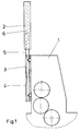
- the printing unit 2 shows a printing unit 1 of a sheetfed offset printing press a pressure plate changer arranged on the delivery side 2.
- the printing plate changer 2 is the plate cylinder new pressure plate to be fed adjustable and also can be provided that a conveyed away from the plate cylinder The printing plate is conveyed into the printing plate changer and there is provided for removal.
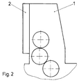
- the pressure plate changer 2 is vertically displaceable compared to that Printing unit 1 attached to this. As shown in Fig. 1, the pressure plate changer 2 each on a side frame wall of the printing unit 1 attached telescopic guide 3 from the Basic position (Fig. 2) moved to a service position (Fig. 1) will.
- the telescopic guide 3 according to the invention consists of three rails 4, 5, 6, each one rail 4 on the Cantilever side of the frame wall 7 (FIG. 3) of the printing unit 1 is arranged.
- An inner rail 5 is, as shown in Fig. 3, over Rolling elements 8 are movable relative to the rail 4 fixed to the frame stored. Again over rolling elements 8 is one at each Outside areas of the pressure plate changer 2 fixed rails 6 movably mounted with respect to the inner rail 5.
- the pressure plate changer 2 is now from the basic position in the extended position shifted, so the two move Rails 5 - on both sides of the pressure plate changer 2 each a rail 5 - partially in length from the rail 4 out.
- those on the pressure plate changer 2 attached rails 6 moved relative to the rails 5, so that the rails 5 only partially in length in the rails 6 immerse yourself.
- FIG. 3 shows the telescopic guide 3, consisting of the rails 4, 5, 6 and the rolling elements 8 arranged in between once again in Detail.
- the rails 4, 5, 6 consist of profiled Material and are in cross section according to the shape of the Rolling body 8 shaped.
- the outer rail 4 is on holder the frame wall 7 arranged.
- the rails 4, 5, 6 on the opposite, not shown frame wall 7 or on the other end of the printing plate changer 2 is a mirror image to the manner shown in FIG. 3.
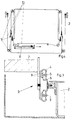
- Fig. 4 shows a drive used for the Pressure plate changer 2, here a traction mechanism in the form a cable is provided.
- ropes 10 over one System of loose and firmly arranged on the pressure plate changer 2 Rolls 9 looped.
- a pneumatic cylinder 11 on the Inside, so the side of the printing unit cylinders facing the Pressure plate changer is arranged, a train on the ropes 10 exercised, so that thereby with a relatively small stroke of the piston rod of the pneumatic cylinder 11 the large travel of the Printing plate changer 2 is made possible.
- the loose rollers 9 this creates a translation of the stroke.
- 4 is the Printing plate changer 2 in its basic position corresponding to FIG. 2 shown.
Landscapes
- Fluid-Damping Devices (AREA)
- Registering, Tensioning, Guiding Webs, And Rollers Therefor (AREA)
- Supply, Installation And Extraction Of Printed Sheets Or Plates (AREA)
- Character Spaces And Line Spaces In Printers (AREA)
- Rotary Presses (AREA)
Applications Claiming Priority (2)
| Application Number | Priority Date | Filing Date | Title |
|---|---|---|---|
| DE9417405U | 1994-10-29 | ||
| DE9417405U DE9417405U1 (de) | 1994-10-29 | 1994-10-29 | Aufhängung für eine dem Wechsel von Druckplatten dienenden Vorrichtung |
Publications (3)
| Publication Number | Publication Date |
|---|---|
| EP0710554A2 EP0710554A2 (de) | 1996-05-08 |
| EP0710554A3 EP0710554A3 (enExample) | 1996-06-05 |
| EP0710554B1 true EP0710554B1 (de) | 1998-02-11 |
Family
ID=6915484
Family Applications (1)
| Application Number | Title | Priority Date | Filing Date |
|---|---|---|---|
| EP95116383A Expired - Lifetime EP0710554B1 (de) | 1994-10-29 | 1995-10-18 | Aufhängung für eine dem Wechseln von Druckplatten dienenden Vorrichtung |
Country Status (3)
| Country | Link |
|---|---|
| EP (1) | EP0710554B1 (enExample) |
| AT (1) | ATE163156T1 (enExample) |
| DE (2) | DE9417405U1 (enExample) |
Families Citing this family (3)
| Publication number | Priority date | Publication date | Assignee | Title |
|---|---|---|---|---|
| DE19803726B4 (de) * | 1998-01-30 | 2007-12-27 | Heidelberger Druckmaschinen Ag | Druckwerk mit einem Druckwerksschutz und einer verstellbaren Aufhängung für den Druckwerksschutz |
| JP4603811B2 (ja) | 2003-07-25 | 2010-12-22 | ハイデルベルガー ドルツクマシーネン アクチエンゲゼルシヤフト | 印刷機に版板を供給し且つ/又は排出するための装置 |
| JP5286033B2 (ja) * | 2008-11-04 | 2013-09-11 | リョービ株式会社 | 印刷機 |
Citations (1)
| Publication number | Priority date | Publication date | Assignee | Title |
|---|---|---|---|---|
| EP0431715A2 (en) * | 1989-12-06 | 1991-06-12 | Komori Corporation | Plate replacing apparatus for printing press |
Family Cites Families (6)
| Publication number | Priority date | Publication date | Assignee | Title |
|---|---|---|---|---|
| JPS61248834A (ja) * | 1985-04-24 | 1986-11-06 | Mitsubishi Heavy Ind Ltd | 枚葉印刷機における刷版交換装置 |
| DE4003445A1 (de) * | 1990-02-06 | 1991-08-08 | Roland Man Druckmasch | Automatisches plattenzufuehr- und zylinderbeschickungssystem |
| DE4224832C3 (de) * | 1991-08-31 | 1999-06-24 | Heidelberger Druckmasch Ag | Vorrichtung zur Positionierung eines dem automatischen Druckplattenwechsel dienenden Magazins |
| DE4130359C2 (de) * | 1991-09-12 | 1997-04-17 | Heidelberger Druckmasch Ag | Vorrichtung zum Ab- und/oder Zuführen von Druckplatten einer Druckmaschine |
| JP2961015B2 (ja) * | 1992-06-29 | 1999-10-12 | 三菱重工業株式会社 | 刷版位置決め装置 |
| DE4226780C2 (de) * | 1992-08-13 | 1994-12-01 | Roland Man Druckmasch | Vorrichtung zur Kontrolle der registergerechten Anlage einer Druckplatte auf dem Plattenzylinder von Druckmaschinen, insbesondere Bogenoffsetdruckmaschinen |
-
1994
- 1994-10-29 DE DE9417405U patent/DE9417405U1/de not_active Expired - Lifetime
-
1995
- 1995-10-18 DE DE59501439T patent/DE59501439D1/de not_active Expired - Fee Related
- 1995-10-18 AT AT95116383T patent/ATE163156T1/de not_active IP Right Cessation
- 1995-10-18 EP EP95116383A patent/EP0710554B1/de not_active Expired - Lifetime
Patent Citations (1)
| Publication number | Priority date | Publication date | Assignee | Title |
|---|---|---|---|---|
| EP0431715A2 (en) * | 1989-12-06 | 1991-06-12 | Komori Corporation | Plate replacing apparatus for printing press |
Also Published As
| Publication number | Publication date |
|---|---|
| DE9417405U1 (de) | 1994-12-08 |
| EP0710554A3 (enExample) | 1996-06-05 |
| DE59501439D1 (de) | 1998-03-19 |
| ATE163156T1 (de) | 1998-02-15 |
| EP0710554A2 (de) | 1996-05-08 |
Similar Documents
| Publication | Publication Date | Title |
|---|---|---|
| DE19937796A1 (de) | Druckwerk | |
| DE3112745A1 (de) | "an einen plattenzylinder einer offset- oder hochdruckmaschine anstellbarer walzenstock" | |
| DE4215355C2 (de) | Waschvorrichtung für Zylinder in Druckmaschinen, insbesondere Bogenoffsetdruckmaschinen | |
| DE2533841A1 (de) | Druckmaschine, insbesondere flexodruckmaschine | |
| DE4410305C2 (de) | Aufhängung für eine als Schutz vor den Druckwerkszylindern einer Druckmaschine dienenden Einrichtung | |
| EP0710554B1 (de) | Aufhängung für eine dem Wechseln von Druckplatten dienenden Vorrichtung | |
| EP0741024B1 (de) | Vorrichtung zum An- und Abstellen von Walzen | |
| DE10103632A1 (de) | Rollenrotationsdruckmaschine | |
| EP0338278B1 (de) | Rotationsdruckmaschine mit einem endlosen Klischeeband | |
| WO2008064960A1 (de) | Verfahren zum betreiben einer druckeinheit mit mindestens einem druckwerk und ein druckwerk zur durchführung des verfahrens | |
| DE10132156B4 (de) | Bahnstabilisierung zur berührungslosen Bahnführung bei fliegend wechselbaren Druckeinheiten | |
| DE3120235C2 (enExample) | ||
| DE3843395A1 (de) | Lagegenaues schnellaufspannen flexibler druckplatten | |
| DE19941943A1 (de) | Verfahren und Vorrichtung zur Entnahme einer Reinigungsvorrichtung aus einer Druckmaschine | |
| EP0968821B1 (de) | Bogentransportzylinder in einer Bogenrotationsdruckmaschine | |
| DE4326833B4 (de) | Druckmaschinenzylinder-Waschvorrichtung | |
| EP1740380B1 (de) | Druckeinheit einer mehrfarbenrollenrotationsdruckmaschine sowie verfahren zu ihrer handhabung | |
| DE4438754C2 (de) | Aufhängung für ein an einem Zylinder einer Druckmaschine an- und abstellbares Andrückelement | |
| DE10209536A1 (de) | Druckmaschine, vorzugsweise Flexodruckmaschine | |
| DE10103631A1 (de) | Rollenrotationsdruckmaschine | |
| DE10242009A1 (de) | Druckmaschine, vorzugsweise Flexodruckmaschine | |
| EP1578607B1 (de) | Modulare druckeinheit | |
| DE701773C (de) | Drucksegmentwalze | |
| EP3653382B1 (de) | Lösbare lageranordnung eines farbwerkzylinders einer druckmaschine | |
| AT500382B1 (de) | Andrückelement in einer druckmaschine |
Legal Events
| Date | Code | Title | Description |
|---|---|---|---|
| PUAI | Public reference made under article 153(3) epc to a published international application that has entered the european phase |
Free format text: ORIGINAL CODE: 0009012 |
|
| PUAL | Search report despatched |
Free format text: ORIGINAL CODE: 0009013 |
|
| 17P | Request for examination filed |
Effective date: 19951103 |
|
| AK | Designated contracting states |
Kind code of ref document: A2 Designated state(s): AT BE CH DE FR GB IT LI NL |
|
| AK | Designated contracting states |
Kind code of ref document: A3 Designated state(s): AT BE CH DE FR GB IT LI NL |
|
| 17Q | First examination report despatched |
Effective date: 19970310 |
|
| GRAG | Despatch of communication of intention to grant |
Free format text: ORIGINAL CODE: EPIDOS AGRA |
|
| GRAG | Despatch of communication of intention to grant |
Free format text: ORIGINAL CODE: EPIDOS AGRA |
|
| GRAH | Despatch of communication of intention to grant a patent |
Free format text: ORIGINAL CODE: EPIDOS IGRA |
|
| GRAH | Despatch of communication of intention to grant a patent |
Free format text: ORIGINAL CODE: EPIDOS IGRA |
|
| ITF | It: translation for a ep patent filed | ||
| GRAA | (expected) grant |
Free format text: ORIGINAL CODE: 0009210 |
|
| AK | Designated contracting states |
Kind code of ref document: B1 Designated state(s): AT BE CH DE FR GB IT LI NL |
|
| REF | Corresponds to: |
Ref document number: 163156 Country of ref document: AT Date of ref document: 19980215 Kind code of ref document: T |
|
| REG | Reference to a national code |
Ref country code: CH Ref legal event code: NV Representative=s name: E. BLUM & CO. PATENTANWAELTE Ref country code: CH Ref legal event code: EP |
|
| ET | Fr: translation filed | ||
| GBT | Gb: translation of ep patent filed (gb section 77(6)(a)/1977) |
Effective date: 19980211 |
|
| REF | Corresponds to: |
Ref document number: 59501439 Country of ref document: DE Date of ref document: 19980319 |
|
| PLBE | No opposition filed within time limit |
Free format text: ORIGINAL CODE: 0009261 |
|
| STAA | Information on the status of an ep patent application or granted ep patent |
Free format text: STATUS: NO OPPOSITION FILED WITHIN TIME LIMIT |
|
| 26N | No opposition filed | ||
| PGFP | Annual fee paid to national office [announced via postgrant information from national office to epo] |
Ref country code: GB Payment date: 20010914 Year of fee payment: 7 |
|
| PGFP | Annual fee paid to national office [announced via postgrant information from national office to epo] |
Ref country code: CH Payment date: 20010917 Year of fee payment: 7 |
|
| PGFP | Annual fee paid to national office [announced via postgrant information from national office to epo] |
Ref country code: NL Payment date: 20010925 Year of fee payment: 7 Ref country code: AT Payment date: 20010925 Year of fee payment: 7 |
|
| PGFP | Annual fee paid to national office [announced via postgrant information from national office to epo] |
Ref country code: BE Payment date: 20011011 Year of fee payment: 7 |
|
| REG | Reference to a national code |
Ref country code: GB Ref legal event code: IF02 |
|
| PGFP | Annual fee paid to national office [announced via postgrant information from national office to epo] |
Ref country code: FR Payment date: 20021009 Year of fee payment: 8 |
|
| PG25 | Lapsed in a contracting state [announced via postgrant information from national office to epo] |
Ref country code: GB Free format text: LAPSE BECAUSE OF NON-PAYMENT OF DUE FEES Effective date: 20021018 Ref country code: AT Free format text: LAPSE BECAUSE OF NON-PAYMENT OF DUE FEES Effective date: 20021018 |
|
| PG25 | Lapsed in a contracting state [announced via postgrant information from national office to epo] |
Ref country code: LI Free format text: LAPSE BECAUSE OF NON-PAYMENT OF DUE FEES Effective date: 20021031 Ref country code: CH Free format text: LAPSE BECAUSE OF NON-PAYMENT OF DUE FEES Effective date: 20021031 Ref country code: BE Free format text: LAPSE BECAUSE OF NON-PAYMENT OF DUE FEES Effective date: 20021031 |
|
| BERE | Be: lapsed |
Owner name: *MAN ROLAND DRUCKMASCHINEN A.G. Effective date: 20021031 |
|
| PG25 | Lapsed in a contracting state [announced via postgrant information from national office to epo] |
Ref country code: NL Free format text: LAPSE BECAUSE OF NON-PAYMENT OF DUE FEES Effective date: 20030501 |
|
| GBPC | Gb: european patent ceased through non-payment of renewal fee |
Effective date: 20021018 |
|
| REG | Reference to a national code |
Ref country code: CH Ref legal event code: PL |
|
| NLV4 | Nl: lapsed or anulled due to non-payment of the annual fee |
Effective date: 20030501 |
|
| PG25 | Lapsed in a contracting state [announced via postgrant information from national office to epo] |
Ref country code: FR Free format text: LAPSE BECAUSE OF NON-PAYMENT OF DUE FEES Effective date: 20040630 |
|
| REG | Reference to a national code |
Ref country code: FR Ref legal event code: ST |
|
| PG25 | Lapsed in a contracting state [announced via postgrant information from national office to epo] |
Ref country code: IT Free format text: LAPSE BECAUSE OF NON-PAYMENT OF DUE FEES;WARNING: LAPSES OF ITALIAN PATENTS WITH EFFECTIVE DATE BEFORE 2007 MAY HAVE OCCURRED AT ANY TIME BEFORE 2007. THE CORRECT EFFECTIVE DATE MAY BE DIFFERENT FROM THE ONE RECORDED. Effective date: 20051018 |
|
| PGFP | Annual fee paid to national office [announced via postgrant information from national office to epo] |
Ref country code: DE Payment date: 20081022 Year of fee payment: 14 |
|
| PG25 | Lapsed in a contracting state [announced via postgrant information from national office to epo] |
Ref country code: DE Free format text: LAPSE BECAUSE OF NON-PAYMENT OF DUE FEES Effective date: 20100501 |