EP0710554A2 - Aufhängung für eine dem Wechseln von Druckplatten dienenden Vorrichtung - Google Patents
Aufhängung für eine dem Wechseln von Druckplatten dienenden Vorrichtung Download PDFInfo
- Publication number
- EP0710554A2 EP0710554A2 EP95116383A EP95116383A EP0710554A2 EP 0710554 A2 EP0710554 A2 EP 0710554A2 EP 95116383 A EP95116383 A EP 95116383A EP 95116383 A EP95116383 A EP 95116383A EP 0710554 A2 EP0710554 A2 EP 0710554A2
- Authority
- EP
- European Patent Office
- Prior art keywords
- plate changer
- printing plate
- printing
- rail
- suspension according
- Prior art date
- Legal status (The legal status is an assumption and is not a legal conclusion. Google has not performed a legal analysis and makes no representation as to the accuracy of the status listed.)
- Granted
Links
- 238000007639 printing Methods 0.000 title claims abstract description 43
- 239000000725 suspension Substances 0.000 claims description 8
- 238000007645 offset printing Methods 0.000 claims description 2
- 230000005540 biological transmission Effects 0.000 claims 1
- 238000005096 rolling process Methods 0.000 abstract description 6
- 238000011161 development Methods 0.000 description 1
- 230000018109 developmental process Effects 0.000 description 1
- 239000000463 material Substances 0.000 description 1
Images

Classifications
-
- B—PERFORMING OPERATIONS; TRANSPORTING
- B41—PRINTING; LINING MACHINES; TYPEWRITERS; STAMPS
- B41F—PRINTING MACHINES OR PRESSES
- B41F27/00—Devices for attaching printing elements or formes to supports
- B41F27/12—Devices for attaching printing elements or formes to supports for attaching flexible printing formes
- B41F27/1206—Feeding to or removing from the forme cylinder
Definitions
- the invention relates to a suspension for a device for changing printing plates according to the preamble of claim 1.
- a device for changing printing plates in the form of a magazine is known that on the delivery side of the printing unit is vertically displaceable via a straight guide attached to a side frame part.
- this magazine can be moved from a basic position to a service position above it.
- the straight guide on the side frames of the printing unit only have a length which corresponds to the dimensions of the magazine, the underside of the magazine still covers parts of the inking unit and, in particular, the ink fountain when pushed up. This is considered to be disadvantageous.
- the object of the present invention is therefore to expand a suspension according to the preamble of claim 1 in such a way that there is optimal accessibility to the upper parts of the inking unit.
- the straight guide for the printing plate change telescopic, so that this completely releases the printing and inking unit in the raised position. It can even be provided that the telescopic linear guides are designed in such a way that the printing plate changer can be moved beyond the printing unit.
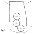
- Fig. 2 shows a printing unit 1 of a sheet-fed offset printing machine with a printing plate changer 2 arranged on the delivery side.
- a new printing plate to be fed to the plate cylinder can be set, and it can also be provided that a printing plate conveyed from the plate cylinder is conveyed into the printing plate changer and there to Removal is provided.
- the printing plate changer 2 is attached to the printing unit 1 in a vertically displaceable manner. As shown in FIG. 1, the printing plate changer 2 can be moved from the basic position (FIG. 2) to a service position (FIG. 1) via a telescopic guide 3 attached to a side frame wall of the printing unit 1.
- the telescopic guide 3 according to the invention consists of three rails 4, 5, 6, one rail 4 each being arranged on the cantilever side of the frame wall 7 (FIG. 3) of the printing unit 1.
- an inner rail 5 is mounted so as to be movable with respect to the rail 4 fixed to the frame via rolling elements 8.
- a rail 6 which is fixedly arranged on the outer regions of the pressure plate changer 2 is movably mounted relative to the inner rail 5.
- the printing plate changer 2 If the printing plate changer 2 is now shifted from the basic position into the extended position, the two rails 5 - one rail 5 on each side of the printing plate changer 2 - partially move out of the rail 4 in their length.
- the rails 6 attached to the pressure plate changer 2 are also moved relative to the rails 5, so that the rails 5 are only partially immersed in the rails 6 in their length. The result of this is that the printing plate changer 2 can be moved into a position above the printing unit 1, so that access to an ink fountain (not shown) or other elements arranged in the upper region of the printing unit 1 is ensured.
- Fig. 3 shows the telescopic guide 3, consisting of the rails 4, 5, 6 and the rolling elements 8 arranged in between again in detail.
- the rails 4, 5, 6 consist of profiled material and are shaped in cross section according to the shape of the rolling elements 8.
- the outer rail 4 is on holder the frame wall 7 arranged.
- the rails 4, 5, 6 on the opposite frame wall 7, not shown, or at the other end of the pressure plate changer 2, are mirror images of the manner shown in FIG. 3.
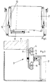
- Fig. 4 shows a preferably used drive for the pressure plate changer 2, wherein a traction mechanism in the form of a cable is provided here.
- ropes 10 are looped over a system of loose rollers 9, which are fixed on the pressure plate changer 2.
- a pneumatic cylinder 11 which is arranged on the inside, i.e. the side of the printing plate changer facing the printing unit cylinders, a pull is exerted on the cables 10, so that the large travel of the printing plate changer 2 is made possible with a relatively small stroke of the piston rod of the pneumatic cylinder 11 .
- the loose rollers 9 thus result in a translation of the stroke. 4 shows the printing plate changer 2 in its basic position corresponding to FIG. 2.
Landscapes
- Fluid-Damping Devices (AREA)
- Registering, Tensioning, Guiding Webs, And Rollers Therefor (AREA)
- Supply, Installation And Extraction Of Printed Sheets Or Plates (AREA)
- Rotary Presses (AREA)
- Character Spaces And Line Spaces In Printers (AREA)
Abstract
Description
- Die Erfindung betrifft eine Aufhängung für eine dem Wechseln von Druckplatten dienenden Vorrichtung gemäß dem Oberbegriff von Anspruch 1.
- Aus der DE 4 224 832 C2 ist eine dem Wechseln von Druckplatten dienende Vorrichtung in Form eines Magazins bekannt, daß an der Auslegerseite des Druckwerkes über je eine an einem Seitengestellteil angebrachte Geradführung vertikal verschiebbar ist. Um manuelle Handhabungen am Druck- oder Farbwerk vorzunehmen, kann dieses Magazin aus einer Grundposition in eine darüber befindliche Serviceposition verschoben werden. Da die Geradführung an den Seitengestellen des Druckwerkes aber nur eine Länge aufweisen, welche der Abmessung der Magazins entsprechen, deckt die Unterseite des Magazins im hochgeschobenen Zustand noch Teile des Farbwerkes und insbesondere den Farbkasten ab. Dies ist als nachteilig anzusehen.
- Aufgabe der vorliegenden Erfindung ist es daher, eine Aufhängung gemäß dem Oberbegriff von Anspruch 1 derartig zu erweitern, so daß sich eine optimale Zugänglichkeit gerade zu den oberen Teilen des Farbwerkes ergibt.
- Gelöst wird diese Aufgabe durch die kennzeichnenden Merkmale von Anspruch 1. Weiterbildungen der Erfindung ergeben sich aus den Unteransprüchen.
- Gemäß der Erfindung ist vorgesehen, die Geradführung für den Druckplattenwechsel teleskopartig auszubilden, so daß dieser in der hochgeschobenen Position das Druck- und Farbwerk vollständig freigibt. Dabei kann sogar vorgesehen sein, die teleskopartig ausgebildeten Geradführungen derartig auszubilden, so daß der Druckplattenwechsler über das Druckwerk hinaus verschoben werden kann.
- Des weiteren erfolgt die Erläuterung eines Ausführungsbeispiels der Erfindung anhand der Zeichnungen.
- Es zeigt:
- Fig. 1
- den erfindungsgemäß aufgehängten Druckplattenwechsler in der hochgeschobenen Position,
- Fig. 2
- den Druckplattenwechsler in seiner Grundposition,
- Fig. 3
- die erfindungsgemäß vorgesehene Teleskopführung im Detail, und
- Fig. 4
- eine Verfahreinrichtung für den Druckplattenwechsler in Form eines Zugmittelgetriebes.
- Fig. 2 zeigt ein Druckwerk 1 einer Bogenoffsetdruckmaschine mit einem an der Auslegerseite angeordneten Druckplattenwechsler 2. In dem Druckplattenwechsler 2 ist eine dem Plattenzylinder zuzuführende neue Druckplatte einstellbar und ferner kann auch vorgesehen sein, daß eine vom Plattenzylinder abgeförderte Druckplatte in den Druckplattenwechsler hereingefördert und dort zur Entnahme bereitgestellt wird.
- Der Druckplattenwechsler 2 ist vertikal verschiebbar gegenüber dem Druckwerk 1 an diesem befestigt. Wie in Fig. 1 dargestellt, kann der Druckplattenwechsler 2 über je eine an einer Seitengestellwand des Druckwerkes 1 angebrachte Teleskopführung 3 aus der Grundposition (Fig. 2) in eine Serviceposition (Fig. 1) verschoben werden. Die erfindungsgemäße Teleskopführung 3 besteht dabei aus drei Schienen 4, 5, 6, wobei jeweils eine Schiene 4 an der Auslegerseite der Gestellwand 7 (Fig. 3) des Druckwerkes 1 angeordnet ist.
- Eine innere Schiene 5 ist, wie in Fig. 3 dargestellt, über Wälzkörper 8 beweglich gegenüber der gestellfesten Schiene 4 gelagert. Wiederum über Wälzkörper 8 ist jeweils eine an den Außenbereichen des Druckplattenwechslers 2 fest angeordnete Schiene 6 beweglich gegenüber der inneren Schiene 5 gelagert.
- Wird der Druckplattenwechsler 2 nun von der Grundposition in die ausgefahrene Position verschoben, so bewegen sich die beiden Schienen 5 - an beiden Seiten des Druckplattenwechsler 2 jeweils eine Schiene 5 - in ihrer Länge teilweise aus dem Schienen 4 heraus. Zusätzlich werden auch die an den Druckplattenwechsler 2 angebrachten Schienen 6 relativ zu den Schienen 5 bewegt, so daß die Schienen 5 in ihrer Länge nur noch teilweise in die Schienen 6 eintauchen. Dadurch ergibt sich, daß der Druckplattenwechsler 2 in eine Position oberhalb des Druckwerkes 1 verschoben werden kann, so daß die Zugänglichkeit zu einem nicht dargestellten Farbkasten oder sonstigen im oberen Bereich des Druckwerkes 1 angeordneten Elementen gewährleistet ist.
- Fig. 3 zeigt die Teleskopführung 3, bestehend aus den Schienen 4, 5, 6 sowie den dazwischen angeordneten Wälzkörpern 8 noch einmal im Detail. Die Schienen 4, 5, 6 bestehen dabei aus profiliertem Material und sind im Querschnitt entsprechend der Form der Wälzkörper 8 geformt. Die äußere Schiene 4 ist dabei über Halter an der Gestellwand 7 angeordnet. Die Schienen 4, 5, 6 an der gegenüberliegenden, nicht dargestellten Gestellwand 7 bzw. an dem anderen Ende des Druckplattenwechslers 2 ist dabei spiegelbildlich zu der in Fig. 3 dargestellten Weise ausgebildet.
- Fig. 4 zeigt einen bevorzugt zum Einsatz kommenden Antrieb für den Druckplattenwechsler 2 wobei hier ein Zugmittelgetriebe in Form eines Seilzuges vorgesehen ist. Hierbei sind Seile 10 über ein System von losen sowie am Druckplattenwechsler 2 fest angeordneten Rollen 9 geschlungen. Über ein Pneumatikzylinder 11, der auf der Innenseite, also der den Druckwerkszylindern zugewandten Seite des Druckplattenwechslers angeordnet ist, wird ein Zug auf die Seile 10 ausgeübt, so daß dadurch bei relativ geringem Hub der Kolbenstange des Pneumatikzylinders 11 der große Verfahrweg des Druckplattenwechslers 2 ermöglicht wird. Durch die losen Rollen 9 entsteht somit eine Übersetzung des Hubes. In Fig. 4 ist der Druckplattenwechsler 2 in seiner Grundstellung entsprechend Fig. 2 dargestellt.
-
- 1
- Druckwerk
- 2
- Druckplattenwechsler
- 3
- Teleskopführung
- 4
- Schiene
- 5
- Schiene
- 6
- Schiene
- 7
- Gestellwand
- 8
- Wälzkörper
- 9
- Rolle
- 10
- Seil
- 11
- Pneumatikzylinder
Claims (6)
- Aufhängung für eine dem Wechseln von Druckplatten dienende Vorrichtung, insbesondere zum Wechseln von Druckplatten bei Bogenoffsetdruckmaschinen, bestehend aus einem Druckplattenwechsler, welcher über Geradführungen vertikal verschiebbar gegenüber dem Druckwerk aufgehängt ist,
dadurch gekennzeichnet,
daß die Geradführungen als Teleskopführungen (3) ausgebildet sind. - Aufhängung nach Anspruch 1,
dadurch gekennzeichnet,
daß die Teleskopführung (3) aus relativ zueinander beweglichen Schienen (4, 5, 6) besteht und jeweils eine Schiene (4) an einer Gestellwand (7) des Druckwerkes (1) und eine Schiene (6) am Druckplattenwechsler (2) angebracht ist. - Aufhängung nach Anspruch 2,
dadurch gekennzeichnet,
daß die Schienen (4, 5, 6) über dazwischen angeordnete Wälzkörper (8) relativ zueinander beweglich gelagert sind. - Aufhängung nach einem vorhergehenden Ansprüche,
dadurch gekennzeichnet,
daß zum Verfahren des Druckplattenwechslers (2) ein Zugmittelgetriebe mittels Antrieb vorgesehen ist. - Aufhängung nach Anspruch 4,
dadurch gekennzeichnet,
daß das Zugmittelgetriebe durch Seile (10) gebildet ist, welche über lose sowie am Druckplattenwechsler (2) angebrachte Rollen geschlungen sind und von einem Hubantrieb betätigt werden. - Aufhängung nach Anspruch 4 oder 5,
dadurch gekennzeichnet,
daß als Antrieb für das Zugmittel bzw. für die Seile (10) ein Pneumatikzylinder (11) vorgesehen ist.
Applications Claiming Priority (2)
| Application Number | Priority Date | Filing Date | Title |
|---|---|---|---|
| DE9417405U | 1994-10-29 | ||
| DE9417405U DE9417405U1 (de) | 1994-10-29 | 1994-10-29 | Aufhängung für eine dem Wechsel von Druckplatten dienenden Vorrichtung |
Publications (3)
| Publication Number | Publication Date |
|---|---|
| EP0710554A2 true EP0710554A2 (de) | 1996-05-08 |
| EP0710554A3 EP0710554A3 (de) | 1996-06-05 |
| EP0710554B1 EP0710554B1 (de) | 1998-02-11 |
Family
ID=6915484
Family Applications (1)
| Application Number | Title | Priority Date | Filing Date |
|---|---|---|---|
| EP95116383A Expired - Lifetime EP0710554B1 (de) | 1994-10-29 | 1995-10-18 | Aufhängung für eine dem Wechseln von Druckplatten dienenden Vorrichtung |
Country Status (3)
| Country | Link |
|---|---|
| EP (1) | EP0710554B1 (de) |
| AT (1) | ATE163156T1 (de) |
| DE (2) | DE9417405U1 (de) |
Cited By (3)
| Publication number | Priority date | Publication date | Assignee | Title |
|---|---|---|---|---|
| EP0933209A3 (de) * | 1998-01-30 | 2000-03-22 | Heidelberger Druckmaschinen Aktiengesellschaft | Verstellbare Aufhängung für einen Druckwerksschutz |
| US7107906B2 (en) | 2003-07-25 | 2006-09-19 | Heidelberger Druckmaschinen Ag | Device for feeding or removing a printing plate including a pivotal plate storage device having a linearly movable plate support |
| JP2010110915A (ja) * | 2008-11-04 | 2010-05-20 | Ryobi Ltd | 印刷機 |
Family Cites Families (7)
| Publication number | Priority date | Publication date | Assignee | Title |
|---|---|---|---|---|
| JPS61248834A (ja) * | 1985-04-24 | 1986-11-06 | Mitsubishi Heavy Ind Ltd | 枚葉印刷機における刷版交換装置 |
| ATE120129T1 (de) * | 1989-12-06 | 1995-04-15 | Komori Printing Mach | Apparat zum wechseln von druckplatten für druckpresse. |
| DE4003445A1 (de) * | 1990-02-06 | 1991-08-08 | Roland Man Druckmasch | Automatisches plattenzufuehr- und zylinderbeschickungssystem |
| DE4224832C3 (de) * | 1991-08-31 | 1999-06-24 | Heidelberger Druckmasch Ag | Vorrichtung zur Positionierung eines dem automatischen Druckplattenwechsel dienenden Magazins |
| DE4130359C2 (de) * | 1991-09-12 | 1997-04-17 | Heidelberger Druckmasch Ag | Vorrichtung zum Ab- und/oder Zuführen von Druckplatten einer Druckmaschine |
| JP2961015B2 (ja) * | 1992-06-29 | 1999-10-12 | 三菱重工業株式会社 | 刷版位置決め装置 |
| DE4226780C2 (de) * | 1992-08-13 | 1994-12-01 | Roland Man Druckmasch | Vorrichtung zur Kontrolle der registergerechten Anlage einer Druckplatte auf dem Plattenzylinder von Druckmaschinen, insbesondere Bogenoffsetdruckmaschinen |
-
1994
- 1994-10-29 DE DE9417405U patent/DE9417405U1/de not_active Expired - Lifetime
-
1995
- 1995-10-18 DE DE59501439T patent/DE59501439D1/de not_active Expired - Fee Related
- 1995-10-18 AT AT95116383T patent/ATE163156T1/de not_active IP Right Cessation
- 1995-10-18 EP EP95116383A patent/EP0710554B1/de not_active Expired - Lifetime
Cited By (5)
| Publication number | Priority date | Publication date | Assignee | Title |
|---|---|---|---|---|
| EP0933209A3 (de) * | 1998-01-30 | 2000-03-22 | Heidelberger Druckmaschinen Aktiengesellschaft | Verstellbare Aufhängung für einen Druckwerksschutz |
| US6142072A (en) * | 1998-01-30 | 2000-11-07 | Heidelberger Druckmaschinen Ag | Adjustable suspension for a printing unit guard |
| DE19803726B4 (de) * | 1998-01-30 | 2007-12-27 | Heidelberger Druckmaschinen Ag | Druckwerk mit einem Druckwerksschutz und einer verstellbaren Aufhängung für den Druckwerksschutz |
| US7107906B2 (en) | 2003-07-25 | 2006-09-19 | Heidelberger Druckmaschinen Ag | Device for feeding or removing a printing plate including a pivotal plate storage device having a linearly movable plate support |
| JP2010110915A (ja) * | 2008-11-04 | 2010-05-20 | Ryobi Ltd | 印刷機 |
Also Published As
| Publication number | Publication date |
|---|---|
| DE59501439D1 (de) | 1998-03-19 |
| EP0710554A3 (de) | 1996-06-05 |
| EP0710554B1 (de) | 1998-02-11 |
| DE9417405U1 (de) | 1994-12-08 |
| ATE163156T1 (de) | 1998-02-15 |
Similar Documents
| Publication | Publication Date | Title |
|---|---|---|
| EP1075945A1 (de) | Druckwerk | |
| DE4028484C2 (de) | ||
| EP1279495A1 (de) | Flexodruckmaschine | |
| DE4215355C2 (de) | Waschvorrichtung für Zylinder in Druckmaschinen, insbesondere Bogenoffsetdruckmaschinen | |
| DE3235646A1 (de) | Vorrichtung zur foerderung von gegenstaenden | |
| EP2604431B1 (de) | Tiefdruckwerk mit Bahnspannungsausgleich und Verfahren zum Warten eines solchen Tiefdruckwerks | |
| DE3843395C2 (de) | Einrichtung zum lagegenauen Schnellaufspannen von flexiblen Druckplatten | |
| EP0728582B1 (de) | Einrichtung zum Reinigen von Zylindern in Druckmaschinen | |
| EP0710554B1 (de) | Aufhängung für eine dem Wechseln von Druckplatten dienenden Vorrichtung | |
| EP0741024B1 (de) | Vorrichtung zum An- und Abstellen von Walzen | |
| DE3120235C2 (de) | ||
| EP1592556B1 (de) | Druckwerk einer druckmaschine | |
| EP1683636B1 (de) | Plattenzylinder mit einer Vorrichtung zur Festlegung von umfangsseitig anbringbaren Druckplatten | |
| EP0338278A2 (de) | Rotationsdruckmaschine mit einem endlosen Klischeeband | |
| WO1997015513A1 (de) | Vorrichtung zum ausziehen von rollpaletten in der kompakt-lagertechnik, sowie rollpalette hierfür | |
| DE4326833B4 (de) | Druckmaschinenzylinder-Waschvorrichtung | |
| DE202010016581U1 (de) | Radsatzpresse | |
| DE3512643A1 (de) | System und vorrichtung zum abstellen von fahrzeugen in mehreren ebenen uebereinander | |
| DE2342129C2 (de) | Garage zum Abstellen zweier Fahrzeuge übereinander | |
| DE1227858B (de) | Liegende Metallstrangpresse mit einem in einem Zylinder gefuehrten Hauptpresskolben | |
| EP0114174A1 (de) | Presse zur Rahmenherstellung | |
| DE102016216768B4 (de) | Fertigungsvorrichtung | |
| DE69005917T2 (de) | Einrichtung für das Positionieren einer Ladung in einem Güterwagen. | |
| DE4039660A1 (de) | Vorrichtung zum anheben oder absenken wenigstens einer achse eines nutzfahrzeuges mit einer druckluftanlage | |
| EP3653382B1 (de) | Lösbare lageranordnung eines farbwerkzylinders einer druckmaschine |
Legal Events
| Date | Code | Title | Description |
|---|---|---|---|
| PUAI | Public reference made under article 153(3) epc to a published international application that has entered the european phase |
Free format text: ORIGINAL CODE: 0009012 |
|
| PUAL | Search report despatched |
Free format text: ORIGINAL CODE: 0009013 |
|
| 17P | Request for examination filed |
Effective date: 19951103 |
|
| AK | Designated contracting states |
Kind code of ref document: A2 Designated state(s): AT BE CH DE FR GB IT LI NL |
|
| AK | Designated contracting states |
Kind code of ref document: A3 Designated state(s): AT BE CH DE FR GB IT LI NL |
|
| 17Q | First examination report despatched |
Effective date: 19970310 |
|
| GRAG | Despatch of communication of intention to grant |
Free format text: ORIGINAL CODE: EPIDOS AGRA |
|
| GRAG | Despatch of communication of intention to grant |
Free format text: ORIGINAL CODE: EPIDOS AGRA |
|
| GRAH | Despatch of communication of intention to grant a patent |
Free format text: ORIGINAL CODE: EPIDOS IGRA |
|
| GRAH | Despatch of communication of intention to grant a patent |
Free format text: ORIGINAL CODE: EPIDOS IGRA |
|
| ITF | It: translation for a ep patent filed | ||
| GRAA | (expected) grant |
Free format text: ORIGINAL CODE: 0009210 |
|
| AK | Designated contracting states |
Kind code of ref document: B1 Designated state(s): AT BE CH DE FR GB IT LI NL |
|
| REF | Corresponds to: |
Ref document number: 163156 Country of ref document: AT Date of ref document: 19980215 Kind code of ref document: T |
|
| REG | Reference to a national code |
Ref country code: CH Ref legal event code: NV Representative=s name: E. BLUM & CO. PATENTANWAELTE Ref country code: CH Ref legal event code: EP |
|
| ET | Fr: translation filed | ||
| GBT | Gb: translation of ep patent filed (gb section 77(6)(a)/1977) |
Effective date: 19980211 |
|
| REF | Corresponds to: |
Ref document number: 59501439 Country of ref document: DE Date of ref document: 19980319 |
|
| PLBE | No opposition filed within time limit |
Free format text: ORIGINAL CODE: 0009261 |
|
| STAA | Information on the status of an ep patent application or granted ep patent |
Free format text: STATUS: NO OPPOSITION FILED WITHIN TIME LIMIT |
|
| 26N | No opposition filed | ||
| PGFP | Annual fee paid to national office [announced via postgrant information from national office to epo] |
Ref country code: GB Payment date: 20010914 Year of fee payment: 7 |
|
| PGFP | Annual fee paid to national office [announced via postgrant information from national office to epo] |
Ref country code: CH Payment date: 20010917 Year of fee payment: 7 |
|
| PGFP | Annual fee paid to national office [announced via postgrant information from national office to epo] |
Ref country code: NL Payment date: 20010925 Year of fee payment: 7 Ref country code: AT Payment date: 20010925 Year of fee payment: 7 |
|
| PGFP | Annual fee paid to national office [announced via postgrant information from national office to epo] |
Ref country code: BE Payment date: 20011011 Year of fee payment: 7 |
|
| REG | Reference to a national code |
Ref country code: GB Ref legal event code: IF02 |
|
| PGFP | Annual fee paid to national office [announced via postgrant information from national office to epo] |
Ref country code: FR Payment date: 20021009 Year of fee payment: 8 |
|
| PG25 | Lapsed in a contracting state [announced via postgrant information from national office to epo] |
Ref country code: GB Free format text: LAPSE BECAUSE OF NON-PAYMENT OF DUE FEES Effective date: 20021018 Ref country code: AT Free format text: LAPSE BECAUSE OF NON-PAYMENT OF DUE FEES Effective date: 20021018 |
|
| PG25 | Lapsed in a contracting state [announced via postgrant information from national office to epo] |
Ref country code: LI Free format text: LAPSE BECAUSE OF NON-PAYMENT OF DUE FEES Effective date: 20021031 Ref country code: CH Free format text: LAPSE BECAUSE OF NON-PAYMENT OF DUE FEES Effective date: 20021031 Ref country code: BE Free format text: LAPSE BECAUSE OF NON-PAYMENT OF DUE FEES Effective date: 20021031 |
|
| BERE | Be: lapsed |
Owner name: *MAN ROLAND DRUCKMASCHINEN A.G. Effective date: 20021031 |
|
| PG25 | Lapsed in a contracting state [announced via postgrant information from national office to epo] |
Ref country code: NL Free format text: LAPSE BECAUSE OF NON-PAYMENT OF DUE FEES Effective date: 20030501 |
|
| GBPC | Gb: european patent ceased through non-payment of renewal fee |
Effective date: 20021018 |
|
| REG | Reference to a national code |
Ref country code: CH Ref legal event code: PL |
|
| NLV4 | Nl: lapsed or anulled due to non-payment of the annual fee |
Effective date: 20030501 |
|
| PG25 | Lapsed in a contracting state [announced via postgrant information from national office to epo] |
Ref country code: FR Free format text: LAPSE BECAUSE OF NON-PAYMENT OF DUE FEES Effective date: 20040630 |
|
| REG | Reference to a national code |
Ref country code: FR Ref legal event code: ST |
|
| PG25 | Lapsed in a contracting state [announced via postgrant information from national office to epo] |
Ref country code: IT Free format text: LAPSE BECAUSE OF NON-PAYMENT OF DUE FEES;WARNING: LAPSES OF ITALIAN PATENTS WITH EFFECTIVE DATE BEFORE 2007 MAY HAVE OCCURRED AT ANY TIME BEFORE 2007. THE CORRECT EFFECTIVE DATE MAY BE DIFFERENT FROM THE ONE RECORDED. Effective date: 20051018 |
|
| PGFP | Annual fee paid to national office [announced via postgrant information from national office to epo] |
Ref country code: DE Payment date: 20081022 Year of fee payment: 14 |
|
| PG25 | Lapsed in a contracting state [announced via postgrant information from national office to epo] |
Ref country code: DE Free format text: LAPSE BECAUSE OF NON-PAYMENT OF DUE FEES Effective date: 20100501 |