EP0710552B1 - Appareil d'enregistrement - Google Patents
Appareil d'enregistrement Download PDFInfo
- Publication number
- EP0710552B1 EP0710552B1 EP95306526A EP95306526A EP0710552B1 EP 0710552 B1 EP0710552 B1 EP 0710552B1 EP 95306526 A EP95306526 A EP 95306526A EP 95306526 A EP95306526 A EP 95306526A EP 0710552 B1 EP0710552 B1 EP 0710552B1
- Authority
- EP
- European Patent Office
- Prior art keywords
- solvent
- stencil sheet
- supplying means
- printing paper
- drum
- Prior art date
- Legal status (The legal status is an assumption and is not a legal conclusion. Google has not performed a legal analysis and makes no representation as to the accuracy of the status listed.)
- Expired - Lifetime
Links
Images

Classifications
-
- B—PERFORMING OPERATIONS; TRANSPORTING
- B41—PRINTING; LINING MACHINES; TYPEWRITERS; STAMPS
- B41M—PRINTING, DUPLICATING, MARKING, OR COPYING PROCESSES; COLOUR PRINTING
- B41M1/00—Inking and printing with a printer's forme
- B41M1/12—Stencil printing; Silk-screen printing
-
- B—PERFORMING OPERATIONS; TRANSPORTING
- B41—PRINTING; LINING MACHINES; TYPEWRITERS; STAMPS
- B41C—PROCESSES FOR THE MANUFACTURE OR REPRODUCTION OF PRINTING SURFACES
- B41C1/00—Forme preparation
- B41C1/14—Forme preparation for stencil-printing or silk-screen printing
- B41C1/147—Forme preparation for stencil-printing or silk-screen printing by imagewise deposition of a liquid, e.g. from an ink jet; Chemical perforation by the hardening or solubilizing of the ink impervious coating or sheet
Definitions
- the present invention concerns a recording apparatus.
- An existent stencil printing apparatus uses heat sensitive stencil sheet comprising a thermoplastic resin film layer laminated on a porous substrate.
- a heating means such as a thermal head having a plurality of dot-like heat generating bodies has been used for example.
- the heat generating bodies of the thermal head and the stencil sheet are moved while being in contact relative to each other and character image information is given in the form of electric signals to the thermal head in synchronization with the movement.
- the heat generating body of the thermal head generates heat selectively to melt and puncture the stencil sheet and form punctured images corresponding to the character image information onto the stencil sheet.
- the perforated stencil sheet is wound around a drum of a stencil printing apparatus.
- An ink supplying device is disposed to the inside of the drum.
- the drum is rotated and, at the same time, an ink is supplied to the inner circumferential surface of the drum and, further, printing paper is fed between a roller disposed outside the drum and the drum.
- the ink transfers passing through an ink passing portion of the drum and the punctured portion of the stencil sheet to the printing paper, by which images corresponding to the punctured images of the stencil sheet are printed on the printing paper.
- the digital printing machine is used in a case of printing a number of identical printed matters simultaneously but, if the number of printing sheets is small, the printing cost is rather increased since the cost of the stencil sheet per sheet of the printed matter requires a high cost.
- a method of directly recording by a thermal head of a digital printing machine to heat sensitive recording paper or heat sensitive transfer recording paper but incorporation of the heat sensitive recording paper or heat sensitive transfer recording paper in the printing machine has a drawback of enlarging the printing machine and complicating the operation of providing both printing paper for stencil printing and recording paper with small number of printing.
- a composite type printing apparatus which combines different printing methods of using only one kind of common paper for the printing paper, conducting electrophotographic printing in a case where the number of printing sheets is small and conducting printing by using heat sensitive stencil sheet in a case of a large number of printing sheets, but it has a drawback that the entire system is complicated, expensive and enlarged in the size.
- an ink-charged drum has to be provided for each of colors, requires a troublesome operation of exchanging the drum upon printing on every color with the drum of the corresponding color also in a partial color printing, to worsen the efficiency.
- Embodiments of the present invention can provide a small-sized recording apparatus capable of overcoming the foregoing problems in the prior art and obtaining printed matters of multiple colors from small number of sheets to a large number of sheet at a low running cost.
- EP-A-0 637 512 discloses a process for platemaking a stencil printing sheet so that there may be no need of preliminarily preparing for manuscripts at a time of platemaking, the consumables, such as a lamp and others, may not be consumed, the stencil sheet can hardly crumple, there may be no sheet loss, and a brilliant printed matter may be obtained.
- the platemaking process according to the present invention is characterised by perforating a stencil sheet having a solvent-soluble resin layer by using the solvent, and feeding the solvent, at a time of platemaking, to the surface of the solvent-soluble resin layer by a solvent feed means selectively and in a non-contact condition thereof, resulting in the solvent-soluble resin layer brought in contact with the solvent is dissolved and perforated.
- GB-A-1,431,462 discloses a process for the production of a relief image by the ink jet process in which an electrically controlled jet of liquid comprising a solution of a substance which is itself capable of altering the solubility properties of a polymer layer with respect to a given solvent or which contributes to the alteration of the solubility properties of a polymer layer with respect to a given solvent is sprayed on to a polymer layer in conformity with the image areas so that the solubility properties of the polymer are modified in those areas which are encountered by the jet of solution and this layer is then treated with said given solvent so that a relief image of the original is obtained.
- GB-A-2,220,815 discloses a recording apparatus according to the preamble of claim 1 and, in particular, a combined duplicating and copying apparatus for either duplicating a large number of copies of copying a smaller number of copies from an original includes a digital imaging unit for generating an image representative digital signal which controls the operation of the thermal heads of a master producing unit for cutting masters for printing, or of a transfer copying unit for producing direct copies of the original.
- the master producing unit thermally cuts masters from a master sheet and then transfers the cut master to a printing drum or drums for duplication onto sheets.
- the copying unit may be used to produce direct copies by melting toner, supplied on a ribbon, which adheres to the copy paper.
- Copying is also envisaged using dot matrix, ink jet and toner vaporisation printing.
- a controller may automatically select duplicating or copying modes according to the number of copies requested through keyboard.
- An auxiliary input is also provided for receiving digital image signals from auxiliary sources such as facsimile machines or computers.
- the recording apparatus of the present invention is characterised by the features of the characterising portion of claim 1 with optional features recited in the dependent claims.
- a recording apparatus of the present invention may comprise a plurality of solvent supplying means for supplying a plurality kinds of solvents containing different kinds of colorants in the first aspect.
- the solvent supplying means may perforate a stencil sheet before attachment to the outer circumferential surface of the drum in the recording apparatus.
- the solvent supplying means may perforate a stencil sheet attached to the outer circumferential surface of the drum in the recording apparatus.
- the solvent supplying means may be made movable between a position for supplying the solvent to the stencil sheet and a position for supplying the solvent to the printing paper in the recording apparatus.
- a first solvent supplying means may be provided for supplying a solvent to the stencil sheet for conducting perforation, and a second solvent supplying means for supplying the solvent to the printing paper for conducting recording.
- stencil sheet having a solvent-soluble resin layer dissolved by a solvent is used.
- the solvent supplying means discharges the solvent selectively in a contactless manner to the solvent-soluble resin layer of the stencil sheet attached to the drum or to the solvent-soluble resin layer of the stencil sheet before attached to the drum.
- the solvent supplied in a contactless manner from the solvent supplying means dissolves the solvent-soluble solution layer.
- a punctured portion is formed to the solvent-soluble solution layer to complete preparation.
- Printing paper is supplied to the drum to which the stencil sheet after make-up is attached.
- the ink supplied by the ink supplying means in the drum transfers by way of the drum and the punctured portion of the stencil sheet to the print paper to apply stencil printing to the printing paper.
- the solvent supplying means supplies the solvent to the printing paper. Since a colorant is contained in the solvent, characters, images, etc. can be recorded simply on the printing paper.
- Both of recording by the solvent supply means suitable to recording for a small number of sheets and printing by using stencil sheet suitable to printing for a large number of sheets can be conducted individually or in combination by merely providing one kind of printing paper and stencil sheet and controlling the solvent supplying means in the recording apparatus.
- Color recording can be conducted by supplying different kinds of solvents containing different colorants from a plurality of solvent supplying means to the printing paper.
- the recording apparatus of this embodiment has a function of conducting stencil printing to printing paper by using stencil sheet and a function of conducting printing by discharging a colorant-incorporated solvent by a solvent supplying means directly to the printing paper.
- the stencil sheet used in the recording apparatus of this embodiment comprises a solvent-soluble resin layer laminated on a porous substrate and its preparation for printing can be conducted by selectively discharging the solvent from the solvent supplying means to the solvent-soluble resin layer of the stencil sheet, thereby dissolving and puncturing the solvent-soluble resin layer.
- stencil printing is conducted in a case requiring a large number of identical printed matters, and recording by the solvent is used in a case where the number of required identical printed matters is small.
- both of the printing methods may be used in combination. That is, both of stencil printing and direct recording by the solvent can be applied to one sheet of printing paper.
- Fig. 2 is a cross sectional view of stencil sheet 20 used in one embodiment of the present invention.
- the stencil sheet 20 is formed with a solvent-soluble resin 21 on one surface of a porous substrate 22.
- the stencil sheet 20 of the above-mentioned structure can be manufactured, for example, by the following exemplified methods (1) - (4).
- porous substrate 22 used in this embodiment there can be mentioned natural fibers such as Manila hemp, pulp, mitsumata, paper mulberry, Japanese paper, synthetic fibers such as polyester, nylon, vinylon and acetate, nonwoven fabric, metal fibers, tissue paper using glass fibers, etc. alone or in admixture, non-woven fabric and screen silk gauze.
- natural fibers such as Manila hemp, pulp, mitsumata, paper mulberry, Japanese paper
- synthetic fibers such as polyester, nylon, vinylon and acetate
- nonwoven fabric such as nonwoven fabric, metal fibers, tissue paper using glass fibers, etc. alone or in admixture, non-woven fabric and screen silk gauze.
- the unit weight of the porous substrate is preferably within a range from 1 to 20 g/m 2 , more preferably within range from 5 to 15 g/m 2 . If it is less than 1 g/m 2 , strength as the stencil sheet is deteriorated. If it exceeds 20 g/m 2 , ink passage upon printing may be deteriorated. Further, the thickness of the porous substrate is preferably within a range from 5 to 100 ⁇ m and, more preferably, within a range 10 to 50 ⁇ m. If it is less than 5 ⁇ m, the strength as the stencil sheet is also deteriorated. If it exceeds 100 ⁇ m, the ink passage upon printing may be worsened.
- the solvent-soluble resin layer 21 used in this embodiment contains a thermoplastic resin or a thermosetting resin soluble to water or a solvent such as an organic solvent as a main ingredient.
- a resin ingredient soluble for water or the organic solvent there can be used, for example, polyethylene, polypropylene, isobutylene, polystyrene, polyvinyl chloride, polyvinylidene chloride, polyvinyl fluoride, polyvinyl acetate, acrylic resin, polyacrylonitrile, polyamide, polyimide, petroleum resin, phenol resin, amino resin, epoxy resin, polyester, polycarbonate, polyurethane, polysulfone, silicone resin, alkyd resin and melamine resin.
- the resin ingredient may be used alone or in admixture or as a copolymer.
- the water soluble resin ingredient there can be used a resin soluble to later or water immiscible organic solvent, for example, polyvinyl alcohol, methyl cellulose, carboxymethyl cellulose, hydroxyethyl cellulose, polyvinyl pyrrolidone, polyethylene - polyvinyl alcohol copolymer, polyethylene oxide, polyvinyl ether, polyvinyl acetal, polyacrylamide, starch, dextrine, alginic acid, ascorbic acid or water soluble urethane.
- the resin may be used alone or in admixture, or may be used as a copolymer.
- the solvent-soluble resin layer 21 may contain, in addition to the resin ingredient, dye, pigment, filler, binder, curing agent and the like.
- the thickness of the solvent-soluble resin layer is desirably within a range from 0.1 to 100 ⁇ m, preferably, within a range from 0.5 to 50 ⁇ m. If the thickness is less than 0.1 ⁇ m, the strength of the resin layer is insufficient. If it exceeds 100 ⁇ m, it requires a great amount of solvent or water for dissolving the resin layer to possibly result insufficient dissolution.
- the solvent for dissolving the solvent-soluble resin layer 21 of the stencil sheet 20 there can be mentioned, for example, aliphatic hydrocarbon type, aromatic hydrocarbon type, alcohol, ketone type, ester type, ether type, aldehyde type, carbonic acid type, amine type, low molecular heterocyclic compound, oxide type and water.
- the solvent is used for conducting preparation by dissolving and puncturing the solvent-soluble resin layer of the stencil sheet, and also to printing by itself other than preparation. Accordingly, it contains a colorant such as a dye or pigment for forming images on the printing paper. Further, the solvent may optionally be incorporated with filler, binder, curing agent, corrosion inhibitor, wetting agent, surfactant and Ph controller.
- the solvent is discharged in the form of droplets by a solvent supplying means.
- a solvent supplying means there can be used a nozzle having 10 to 2,000 (10 to 2,000 dpi) apertures per one inch, slit, injector, porous member, porous film connected to piezoelectric device, heat generating device, electric field device or liquid feeding pump.
- the solvent can be discharged intermittently or continuously in accordance with character image signals.
- Fig. 3 shows a schematic view of preparation of the stencil sheet 10 in this embodiment.
- a solvent 24 discharged selectively in a contactless manner in accordance with image signals from the solvent supplying means is supplied on a solvent-soluble resin layer 21 of stencil sheet 20.
- the supplied solvent 24 dissolves and punctures the solvent-soluble resin layer 21 and a solution 26 is penetrated and diffused into the porous substrate 22 and a punctured portion 25 is formed to the solvent-soluble resin layer 21 at a portion in contact with the solvent 24 to perforate the stencil sheet 20.
- the solvent supplying means 23 is used for perforating the stencil sheet 20 as described above and can record characters or images by discharging the solvent directly to the printing paper. That is, the solvent 24 discharged selectively in a contactless manner in accordance with the image signals from the solvent supplying means 23 is supplied on the printing paper. Since the solvent contains a colorant, when the solvent is dried, images of a color depending on the colorant are formed on the printing paper.
- the recording apparatus 10 has a perforating function of perforating the stencil sheet 20 by dissolving and puncturing the solvent-soluble resin layer 21 with the solvent, and a stencil printing function of conducting stencil printing by using the perforated stencil sheet 20.
- the stencil printing is effective in a case of obtaining a large number of identical printed matters.
- the recording apparatus 10 also has a function of forming images by directly discharging the solvent to the printing paper 11. Image formation by the discharge of the solvent is effective in a case where the number of printing sheets of identical printed matters to be obtained is relatively small.
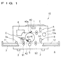
- the recording apparatus 10 has a cylindrical drum 41 as a stencil printing means.
- the cylinder plate 41 is rotatable around a central axis of its own, and rotationally driven by a motor as a driving means not illustrated in a counterclockwise direction in the drawing.
- a portion of a circumferential wall of the drum 41 is an ink permeable region.
- An ink supplying means is disposed in the drum 41.
- the ink supplying means supplies an ink 42 to the inner surface of the circumferential wall of the drum 41.
- the ink 42 supplied to the inner surface of the circumferential wall of the drum 41 is squeezed from the ink permeable region of the circumferential wall to the outside by a squeezing roller 43 disposed in the drum 41.
- the squeezed out ink 42 is externally squeezed by way of punctured images of the stencil sheet 20 wound around the drum 40 and deposited to the supplied printing paper 11 to form images.
- an ink used generally for stencil printing for example, oily ink, aqueous ink, water-in-oil droplet (W/O) type emulsion ink, oil-in-water (O/W) type emulsion ink can be utilized.
- a clamp plate 40 as a stencil sheet holding means is disposed to the outside of the circumferential wall of the drum 41.
- a shaft 40a is disposed in parallel with one of generators of the drum 41 at a portion other than the ink permeable region of the circumferential wall of the drum 41.
- the clamp plate 40 is rotatable around the shaft 40a as the center. As shown in Fig. 1, when the clamp plate 40 reaches the topmost position of the drum 41, the clamp plate 40 holds the top end of the stencil sheet 20 supplied to the drum 41 by sandwiching it relative to the outer surface of the drum 41.
- the stencil sheet 20 rolled cylindrically is disposed to the upper right of the drum 41.
- the stencil sheet 20 is supplied by a conveyor roller 93 to the topmost portion of the drum 41.
- the stencil sheet 20 is supplied to the drum 41 and the top end of the supplied stencil sheet 20 is held by the clamp plate 40.
- the drum 41 rotates in a counterclockwise direction in Fig. 1 and, when the conveyor roller 90 continuously delivers the stencil sheet 20 at an appropriate conveying speed, the stencil sheet 20 is wound around to the outer circumferential surface of the drum 41 under a predetermined tension.
- a plate discharge portion 6 is disposed to the upper left of the drum 41 for discarding the stencil sheet 20.
- the plate discharge portion 6 has a function of stripping off the used stencil sheet 20 from the drum 41, introducing it into a containing box and compressing it.
- a paper feed tray 7 is disposed to the lower left of the drum 41 for supplying the printing paper 11.
- a plurality of printing paper 11 stacked on the paper feed tray 7 are sent orderly from upper one by a pick-up roller 7a to the drum 41.
- the sent printing paper 11 is conveyed by a conveyor roller 91 as the conveying means so as to pass a position below the drum 41.
- a press roller 5 is disposed below the drum 41 at a predetermined distance with the drum 41.
- the press roller 5 in this embodiment is vertically movable and moves vertically in synchronization with the rotation of the drum 41 and the conveyance of the printing paper 11 by the conveyor roller 91. That is, when the printing paper 11 is supplied between the drum 41 and the press roller 5 in synchronization with the rotation of the drum 41, the press roller 5 raises to sandwich the printing paper 11 relative to the drum 41 and conveys the printing paper 11 rightwardly in the drawing.
- the printing paper 11 is applied with stencil printing.
- a conveyor roller 92 as a conveying means for conveying the printed paper 12 rightvardly in the drawing and a paper discharge tray 8 for receiving the printing paper 12 conveyed to the conveyor roller 92 and containing by successively stacking them are provided to the lower right of the drum 41.
- an image sensor 1 as a document reading means is disposed substantially above the drum 41.
- the image sensor 1 reads image of a document and outputs the image information as electric signals.
- the images referred to herein should be considered in a most broad meaning containing not only pictures, photographs, graphics and patterns but also characters and they include all objects that can be recognized visually irrespective of colors.
- a solvent supplying means 2 is disposed to the light of the drum 41 with the solvent being discharged downwardly.
- the solvent supplying means 2 has an identical constitution with the solvent supplying means 23.
- the solvent supplying means 2 is vertically movable to the light of the drum 41 and is selectively set at two positions A and B shown in Fig. 1.
- the position A is a position for perforating the stencil sheet 20.
- the solvent supplying means at the position A conducts preparation by selectively discharging the solvent 24 in a contactless manner to the stencil sheet 20 conveyed by the conveyor roller 93 to the drum 41.
- the position B is a position for recording images to the printing paper 11 by the solvent 24.
- the solvent supplying means 2 at the position B discharges the solvent 24 selectively in a contactless manner to the printing paper 11 conveyed by the conveyor roller 92 to form images on the printing paper 11.
- Selection for the setting position of the solvent supplying means 2 and discharge of the solvent 24 by the solvent supplying means 2 are conducted by a not illustrated driving control means.
- the driving control means controls driving of the drum 41, conveyance of the printing paper 11 or the like.
- the solvent supplying means 2 is driven in synchronization with the driving for each of the portions of the recording apparatus in accordance with the image signals outputted from the image sensor 1.
- the driving control means of this embodiment has a function of controlling the preparation of the stencil sheet 20, stencil printing using the perforated stencil sheet 20 and the operation of solvent recording or the like and may also has a function of controlling other operations appended to the above-mentioned operation, for example, an operation of winding the stencil sheet 20 around the drum 41 or plate discharging operation after printing.
- the driving control means of this embodiment can drive the solvent supplying means 2 by the image signals from the image sensor 1 and it can also drive the solvent supplying means 2 by image signals supplied from the outside of this recording apparatus 10.
- the document may be read by an image processing device disposed to the outside of the recording apparatus 10 and the image information obtained therefrom may be supplied to the driving control means of this recording apparatus 10 to conduct preparation by the solvent supplying means 2.
- Each of the constituent portions of the recording apparatus 10 described above is assembled to a not illustrated substrate and the entire portion is substantially covered with a casing 10a.
- the paper feed tray 7 and the paper discharge tray 8 can easily be attached and detached to the cosign 10a manually by an operator. Accordingly, the size of the printing paper 11 can optionally be selected as required.
- Fig. 1 when a document is present, image signals read by the image sensor 1 are sent to the driving control means.
- image signals from other image signal supplying means such as personal computer (not illustrated) at the outside of the recording apparatus 10 are sent to the driving control means of the recording apparatus 10.
- the image signals held by the driving control means of the recording apparatus 10 are utilized for stencil printing and/or direct recording by the solvent supplying means 2, for example, in accordance with the instruction from the outside.
- the solvent supplying means 2 is used as the recording means.
- the solvent supplying means 2 is set near the conveying path of the printing paper 11.
- the means is disposed at the position B as described above.
- the printing paper 11 on the paper feed tray 7 is transported by the conveyor roller 91 and displaced by the conveyor roller 92 below the solvent supplying means 2 at the position B.
- the solvent supplying means 2 selectively discharges the colorant containing solvent 24 in synchronization with the transportation of the printing paper 11 to form images on the printing paper 11.
- the printing paper 11 formed with the images is conveyed by the conveyor roller 92 to the paper discharge tray 8 and stocked as the printing paper 12.
- the press roller 5 Upon recording for a small number of sheets by the solvent supplying means 2, the press roller 5 is apart from the drum 41 and does not interfere with the conveyed printing paper 11.
- the stencil sheet 20 is made-up and stencil printing is applied.
- the solvent supplying means 2 is disposed near the stencil sheet 10. In this embodiment, the means is disposed at the position A as described above.
- the stencil sheet 20 is delivered by the conveyor roller 93.
- the solvent supplying means 2 disposed at the position A discharges the solvent to the stencil sheet 20 conveyed by the conveyor roller 93, that is, to the stencil sheet 20 before attached to the drum 41.
- the perforated stencil sheet 20 is conveyed by the conveyor roller 93 toward the paper cylinder 41, and the top end is held by the clamp plate 40. Along with the rotation of the drum 41, the stencil sheet 20 is wound around the outer circumferential surface of the drum 41 while undergoing tension. The stencil sheet 20 is cut by a not illustrated cutter. The stencil sheet 20 is wound around the drum 41 with no creasing.
- the printing paper 11 on the paper feed tray 7 is transported by the conveyor roller 91 and is tightly bonded to the stencil sheet 20 while being put between the press roller 5 and the drum 41.
- the ink 42 passing from the punctured portion of the made-up stencil sheet 20 transfers to the printing paper 11 to conduct stencil printing.
- the printing paper 12 after printing is conveyed by the conveyor roller 92 as far as the paper discharge tray 8 and then stocked.
- the dotted arrow in Fig. 1 indicates the conveying path of the printing paper 11, 12. Since no molten products remain in the punctured portion of the perforated stencil sheet 20, passage of the ink is not hindered and clear printed matter can be obtained.
- the recording apparatus 10 of this embodiment can provide printed matters applied with both of recordings of the direct recording by the colorant-containing solvent and recording by stencil printing on one identical printing paper.
- the stencil sheet 10 is made-up by the solvent supplying means 2 set at the position A and wound around the drum 41 to conduct stencil printing.
- the solvent supplying means 2 is set at the position B.
- the stencil printing operation and the solvent direct recording can be conducted continuously on every sheets of printing paper. Further, the stencil printing operation and the solvent direct printing can be conducted separately in different steps. For example, stencil printing is at first applied to a required number of sheets of printing paper, the printing paper after stencil printing is returned again to the paper feed tray 7 and the direct printing with the solvent may be conducted to the printing paper in the subsequent step. Alternatively, the direct recording by the solvent is applied previously and the printing paper after direct recording is put to stencil printing.
- one solvent supplying means 2 is disposed and direct recording to the printing paper 11 and preparation to the stencil sheet 20 can be conducted selectively by varying the position.
- direct recording and solvent supplying means may be disposed respectively and fixedly arranged, for example, on the positions A and B.
- one solvent supplying means 2 may be disposed at a position C left to the drum 41.
- the solvent supplying means 2 is movable between a first position for directing the top end of discharging solvent to the circumferential surface of the drum 41 and a second position of directing the top end to the transported printing paper 11.
- a concrete structure for making the solvent supplying means 2 movable in such a way can be provided by disposing a rotational shaft at the end opposite to the end of discharging solvent and making the solvent supplying means 2 rotatable by about 90 degrees around the rotational shaft as the center.
- the stencil sheet 20 is made-up after attaching the stencil sheet 20 to the drum 41. Since the stencil sheet 20 is wound around the drum 41 and then the solvent is discharged in a contactless manner from the solvent supplying means 20 to conduct make-up no creasing occurs to the stencil sheet 20. Further, when the stencil sheet 20 is attached to the drum 41, even if the stencil sheet 20 runs obliquely and is attached obliquely, or even if creasing should occur, since make-up is applied in a contactless manner to the stencil sheet 20, the stencil sheet 20 is not wasted.
- the printing paper 11 is at first put to direct recording by the solvent and immediately thereafter, put to stencil printing and then discharged to the paper discharge tray 8. Also in the recording apparatus in which one solvent supplying means 2 is disposed at the positions C, direct recording by the solvent and the stencil printing can be conducted separately in different steps.
- the tone of the solvent discharged from the solvent supplying means 2 may be different from the tone of the ink in the drum 41 used upon printing a number of sheets.
- the tone of the solvent is, for example, red and blue which is used less frequently
- the ink in the drum 41 is a black or like other ink which is used frequently
- black printing for a number of sheets by stencil printing using the drum 41 and direct recording, for example, red and blue which is used less frequently can be conducted simply on one sheet of recording paper and multi-colored printed matters can be obtained efficiently.
- the solvent supplying means for direct recording by the solvent is provided by one, a plurality of solvent supplying means for discharging solvents of different tones may be disposed so that direct recording can be applied to the printing paper by a plurality of colors. Particularly, it may be adapted such that three kinds of solvents having each of three primary color tones can be selectively discharged to the printing paper and full color images are formed on the printing paper.
- the recording apparatus has a solvent supplying means for discharging a colorant-containing solvent
- the stencil sheet having the solvent-soluble resin layer can be perforated by the solvent supplying means and the solvent can be discharged directly from the solvent supplying means to the printing paper to conduct recording. Accordingly, both of direct printing and stencil printing can be applied to one kind of printing paper, and recording for a small number of sheets and printing for a large number of sheets can be conducted at a reduced running cost efficiently by one small-sized recording apparatus. Further, color recording can also be conducted at a low cost.
Landscapes
- Engineering & Computer Science (AREA)
- Manufacturing & Machinery (AREA)
- Manufacture Or Reproduction Of Printing Formes (AREA)
- Printing Plates And Materials Therefor (AREA)
Claims (10)
- Appareil d'enregistrement (10) comprenant :un tambour (41) qui est entraíné en rotation autour d'un axe central du tambour (41), une feuille stencil (20) étant enroulée autour de la surface circonférentielle extérieure du tambour (41), etun moyen d'alimentation en encre, disposé à l'intérieur du tambour, et appliquant une encre (42) sur la surface circonférentielle intérieure du tambour (41), caractérisé par :le stencil comportant une couche de résine soluble dans un solvant (21), etun moyen de distribution de solvant pouvant être mis en oeuvre pour appliquer de façon sélective un solvant (24) contenant un colorant sur la feuille stencil (20), en vue de perforer la feuille stencil (20), et pour appliquer de façon sélective le solvant (24) sur le papier d'impression (11) afin d'effectuer un enregistrement.
- Appareil d'enregistrement (10) selon la revendication 1, dans lequel une pluralité de moyens de distribution de solvant, destinés à délivrer une pluralité de types de solvants contenant des types différents de colorants, respectivement, est prévue.
- Appareil d'enregistrement (10) selon la revendication 1 ou 2, dans lequel le moyen de distribution de solvant perfore la feuille stencil (20) avant qu'elle soit fixée à la surface circonférentielle extérieure du tambour (41).
- Appareil d'enregistrement (10) selon la revendication 1 ou 2, dans lequel le moyen de distribution de solvant perfore la feuille stencil (20) fixée à la surface circonférentielle extérieure du tambour (41).
- Appareil d'enregistrement (10) selon l'une quelconque des revendications précédentes, dans lequel le moyen de distribution de solvant peut être déplacé entre une position permettant d'appliquer le solvant sur la feuille stencil (20) et une position permettant d'appliquer le solvant sur le papier d'impression (11).
- Appareil d'enregistrement (10) selon l'une quelconque des revendications 1 à 4, comportant un premier moyen de distribution de solvant permettant d'effectuer la perforation de la feuille stencil (20) en appliquant le solvant (24) sur celle-ci, et un second moyen de distribution de solvant permettant d'effectuer un enregistrement en appliquant le solvant (24) sur le papier d'impression (11).
- Procédé de mise en oeuvre d'un appareil d'enregistrement selon l'une quelconque des revendications précédentes, comprenant la détermination du nombre de feuilles de papier d'impression (11) à enregistrer et, en fonction de ce nombre, la mise en oeuvre du moyen de distribution de solvant afin d'appliquer le solvant sur la feuille stencil (20) ou sur le papier d'impression (11).
- Procédé de mise en oeuvre d'un appareil d'enregistrement selon l'une quelconque des revendications 1 à 6, comprenant la mise en oeuvre du moyen de distribution de solvant pour appliquer du solvant à la fois sur la feuille stencil (20) et sur le papier d'impression (11).
- Procédé de mise en oeuvre d'un appareil d'enregistrement selon la revendication 8, dans lequel le moyen de distribution de solvant applique tout d'abord du solvant sur la feuille stencil (20), un nombre voulu de feuilles de papier d'impression (11) sont imprimées par stencil à l'aide de la feuille stencil, les feuilles imprimées de papier d'impression sont renvoyées à un bac d'alimentation en papier, et le moyen de distribution de solvant est ensuite mis en oeuvre afin d'appliquer du solvant pour, en outre, imprimer directement le papier d'impression imprimé par stencil.
- Procédé de mise en oeuvre d'un appareil d'enregistrement selon la revendication 8, dans lequel le moyen de distribution de solvant applique tout d'abord du solvant sur le papier d'impression afin d'imprimer directement un nombre voulu de feuilles de papier d'impression (11), les feuilles imprimées de papier d'impression sont renvoyées à un bac d'alimentation en papier, le moyen de distribution de solvant est ensuite mis en oeuvre afin d'appliquer du solvant sur la feuille stencil (20), et ensuite, le papier d'impression imprimé directement est, en outre, imprimé par stencil.
Applications Claiming Priority (2)
| Application Number | Priority Date | Filing Date | Title |
|---|---|---|---|
| JP6221783A JPH0885249A (ja) | 1994-09-16 | 1994-09-16 | 記録装置 |
| JP221783/94 | 1994-09-16 |
Publications (3)
| Publication Number | Publication Date |
|---|---|
| EP0710552A2 EP0710552A2 (fr) | 1996-05-08 |
| EP0710552A3 EP0710552A3 (fr) | 1996-11-06 |
| EP0710552B1 true EP0710552B1 (fr) | 1998-07-08 |
Family
ID=16772140
Family Applications (1)
| Application Number | Title | Priority Date | Filing Date |
|---|---|---|---|
| EP95306526A Expired - Lifetime EP0710552B1 (fr) | 1994-09-16 | 1995-09-15 | Appareil d'enregistrement |
Country Status (4)
| Country | Link |
|---|---|
| US (1) | US5662039A (fr) |
| EP (1) | EP0710552B1 (fr) |
| JP (1) | JPH0885249A (fr) |
| DE (1) | DE69503337T2 (fr) |
Families Citing this family (21)
| Publication number | Priority date | Publication date | Assignee | Title |
|---|---|---|---|---|
| JP3542859B2 (ja) * | 1995-10-05 | 2004-07-14 | 理想科学工業株式会社 | 複式印刷装置 |
| JPH09277487A (ja) * | 1996-02-16 | 1997-10-28 | Riso Kagaku Corp | 感熱孔版原紙の製版方法並びにそれに用いる感熱孔版原紙及び組成物 |
| JPH09327899A (ja) * | 1996-06-10 | 1997-12-22 | Riso Kagaku Corp | 感熱孔版原紙の製版方法 |
| JPH1086545A (ja) * | 1996-09-13 | 1998-04-07 | Riso Kagaku Corp | 感熱孔版原紙製版用組成物及び製版方法 |
| JPH10181177A (ja) * | 1996-12-27 | 1998-07-07 | Tohoku Ricoh Co Ltd | 印刷方法および印刷装置 |
| JPH10264493A (ja) * | 1997-03-24 | 1998-10-06 | Riso Kagaku Corp | 複式印刷装置 |
| JPH10264351A (ja) * | 1997-03-28 | 1998-10-06 | Riso Kagaku Corp | 複式印刷装置及び複式印刷装置における記録方法 |
| JPH10337839A (ja) * | 1997-06-09 | 1998-12-22 | Riso Kagaku Corp | 孔版印刷方法、孔版印刷原版、孔版印刷原版の製造方法、及び孔版印刷装置 |
| DE69718063T2 (de) * | 1997-07-11 | 2003-09-25 | Autotype International Ltd., Wantage | Herstellung einer siebdruckschablone |
| GB2333997B (en) | 1998-02-06 | 2002-07-17 | Autotype Internat Ltd | Screen printing stencil production |
| GB2335392B (en) | 1998-02-17 | 2001-11-07 | Autotype Internat Ltd | Screen printing stencil production |
| US6558458B1 (en) | 1999-09-17 | 2003-05-06 | American Ink Jet Corporation | Systems and methods for lithography |
| US6681691B2 (en) | 2000-03-02 | 2004-01-27 | Autotype International Limited | Screen printing stencil production |
| FR2807772B1 (fr) * | 2000-04-12 | 2002-07-26 | Porcher Ind | Support imprimable resistant au feu |
| US6315916B1 (en) | 2000-05-08 | 2001-11-13 | Pisces-Print Image Sciences, Inc. | Chemical imaging of a lithographic printing plate |
| US6691618B2 (en) | 2000-05-08 | 2004-02-17 | Pisces-Print Imaging Sciences, Inc. | Chemical imaging of a lithographic printing plate |
| US20040154489A1 (en) * | 2000-05-08 | 2004-08-12 | Deutsch Albert S. | Chemical imaging of a lithographic printing plate |
| JP3433177B2 (ja) * | 2000-10-31 | 2003-08-04 | 理想科学工業株式会社 | ハイブリッド孔版印刷装置、ハイブリッド孔版印刷装置の制御方法、及び制御プログラム |
| US7809156B2 (en) | 2005-08-12 | 2010-10-05 | Ricoh Company, Ltd. | Techniques for generating and using a fingerprint for an article |
| US7865124B2 (en) * | 2007-03-30 | 2011-01-04 | Ricoh Company, Ltd. | Pre-scanning printer with paper fingerprinting |
| US8756673B2 (en) | 2007-03-30 | 2014-06-17 | Ricoh Company, Ltd. | Techniques for sharing data |
Citations (2)
| Publication number | Priority date | Publication date | Assignee | Title |
|---|---|---|---|---|
| EP0637512A1 (fr) * | 1993-08-04 | 1995-02-08 | Riso Kagaku Corporation | Procédé pour imager une feuille stencil |
| US5417156A (en) * | 1992-10-02 | 1995-05-23 | Ricoh Company, Ltd. | Thermal stencil plate making method |
Family Cites Families (10)
| Publication number | Priority date | Publication date | Assignee | Title |
|---|---|---|---|---|
| DE2253944C2 (de) * | 1972-11-03 | 1983-02-24 | Agfa-Gevaert Ag, 5090 Leverkusen | Verfahren zur Herstellung eines Reliefbildes |
| JPS5583079A (en) * | 1978-12-18 | 1980-06-23 | Ricoh Co Ltd | Information writable copying apparatus |
| US4423676A (en) * | 1981-05-08 | 1984-01-03 | Cannon Mills Company | Method and apparatus for printing composite designs on fabric |
| US4597829A (en) * | 1982-10-08 | 1986-07-01 | Pilot Man-Nen-Hitsu Kabushiki Kaisha | Stencil, stencil material kit and stencil duplicator kit containing the same |
| JPS6112387A (ja) * | 1984-06-29 | 1986-01-20 | Takara Co Ltd | 印刷玩具用原版セツト |
| JPS6112395A (ja) * | 1984-06-29 | 1986-01-20 | Takara Co Ltd | 印刷玩具用原紙 |
| GB2220815A (en) * | 1988-07-11 | 1990-01-17 | Gestetner Mfg Ltd | Combined duplicator and copier apparatus |
| US5154121A (en) * | 1988-11-09 | 1992-10-13 | Man Roland Druckmaschinen Ag | System and method to apply a printing image on a printing machine cylinder having ink accepting receptors or cells, in accordance with electronically furnished image information |
| CA2090642C (fr) * | 1992-05-01 | 1999-06-22 | Thomas N. Taylor | Imprimante xerographique/thermique a jet d'encre combinee |
| IL106899A (en) * | 1993-09-03 | 1995-08-31 | Adler Uri | Method and apparatus for the production of photopolymeric printing plates |
-
1994
- 1994-09-16 JP JP6221783A patent/JPH0885249A/ja active Pending
-
1995
- 1995-09-08 US US08/525,141 patent/US5662039A/en not_active Expired - Fee Related
- 1995-09-15 DE DE69503337T patent/DE69503337T2/de not_active Expired - Fee Related
- 1995-09-15 EP EP95306526A patent/EP0710552B1/fr not_active Expired - Lifetime
Patent Citations (2)
| Publication number | Priority date | Publication date | Assignee | Title |
|---|---|---|---|---|
| US5417156A (en) * | 1992-10-02 | 1995-05-23 | Ricoh Company, Ltd. | Thermal stencil plate making method |
| EP0637512A1 (fr) * | 1993-08-04 | 1995-02-08 | Riso Kagaku Corporation | Procédé pour imager une feuille stencil |
Also Published As
| Publication number | Publication date |
|---|---|
| DE69503337T2 (de) | 1999-01-28 |
| EP0710552A2 (fr) | 1996-05-08 |
| US5662039A (en) | 1997-09-02 |
| JPH0885249A (ja) | 1996-04-02 |
| EP0710552A3 (fr) | 1996-11-06 |
| DE69503337D1 (de) | 1998-08-13 |
Similar Documents
| Publication | Publication Date | Title |
|---|---|---|
| EP0710552B1 (fr) | Appareil d'enregistrement | |
| EP0771647B1 (fr) | Dispositif d'impression par stencil | |
| GB2238757A (en) | Stencil duplicator capable of immediate restart | |
| EP0867306B1 (fr) | Dispositif et méthode d'impression par stencil thermosensible | |
| EP0637512B1 (fr) | Procédé pour imager une feuille stencil | |
| US5713278A (en) | Plate-making method and apparatus for stencil sheet | |
| JP3062443B2 (ja) | 印刷機 | |
| EP0703090B1 (fr) | Dispositif d'impression par stencil | |
| JP3441023B2 (ja) | 多色印刷方法およびそれを用いた多色印刷装置 | |
| EP0867305B1 (fr) | Dispositif d'impression par stencil thermosensible | |
| JPH0544139Y2 (fr) | ||
| JPH068612A (ja) | プリンタ兼用製版印刷装置 | |
| JP2002193498A (ja) | 熱転写プリンター、熱転写記録方法及び熱転写受像シートロール | |
| JP3200230B2 (ja) | 孔版印刷装置 | |
| EP1225059A2 (fr) | Feuille stencil, procédé de sa fabrication et procédé de fabrication d'une plaque stencil | |
| JP2000246885A (ja) | 記録装置及び複合印刷装置 | |
| JPH07214743A (ja) | 孔版印刷装置の製版装置 | |
| JPH0664347A (ja) | 感熱転写記録方法、感熱転写記録装置及び感熱転写記録用インクシート | |
| JPS62290538A (ja) | ステンシル原紙穿孔方法 | |
| JPS62290560A (ja) | プリンタ兼用製版装置 |
Legal Events
| Date | Code | Title | Description |
|---|---|---|---|
| PUAI | Public reference made under article 153(3) epc to a published international application that has entered the european phase |
Free format text: ORIGINAL CODE: 0009012 |
|
| AK | Designated contracting states |
Kind code of ref document: A2 Designated state(s): DE FR GB |
|
| 17P | Request for examination filed |
Effective date: 19960704 |
|
| PUAL | Search report despatched |
Free format text: ORIGINAL CODE: 0009013 |
|
| AK | Designated contracting states |
Kind code of ref document: A3 Designated state(s): DE FR GB |
|
| 17Q | First examination report despatched |
Effective date: 19970428 |
|
| GRAG | Despatch of communication of intention to grant |
Free format text: ORIGINAL CODE: EPIDOS AGRA |
|
| GRAG | Despatch of communication of intention to grant |
Free format text: ORIGINAL CODE: EPIDOS AGRA |
|
| GRAH | Despatch of communication of intention to grant a patent |
Free format text: ORIGINAL CODE: EPIDOS IGRA |
|
| GRAH | Despatch of communication of intention to grant a patent |
Free format text: ORIGINAL CODE: EPIDOS IGRA |
|
| GRAA | (expected) grant |
Free format text: ORIGINAL CODE: 0009210 |
|
| AK | Designated contracting states |
Kind code of ref document: B1 Designated state(s): DE FR GB |
|
| REF | Corresponds to: |
Ref document number: 69503337 Country of ref document: DE Date of ref document: 19980813 |
|
| ET | Fr: translation filed | ||
| PLBE | No opposition filed within time limit |
Free format text: ORIGINAL CODE: 0009261 |
|
| STAA | Information on the status of an ep patent application or granted ep patent |
Free format text: STATUS: NO OPPOSITION FILED WITHIN TIME LIMIT |
|
| 26N | No opposition filed | ||
| REG | Reference to a national code |
Ref country code: GB Ref legal event code: IF02 |
|
| PGFP | Annual fee paid to national office [announced via postgrant information from national office to epo] |
Ref country code: FR Payment date: 20030904 Year of fee payment: 9 |
|
| PGFP | Annual fee paid to national office [announced via postgrant information from national office to epo] |
Ref country code: GB Payment date: 20030910 Year of fee payment: 9 |
|
| PG25 | Lapsed in a contracting state [announced via postgrant information from national office to epo] |
Ref country code: GB Free format text: LAPSE BECAUSE OF NON-PAYMENT OF DUE FEES Effective date: 20040915 |
|
| PGFP | Annual fee paid to national office [announced via postgrant information from national office to epo] |
Ref country code: DE Payment date: 20041130 Year of fee payment: 10 |
|
| GBPC | Gb: european patent ceased through non-payment of renewal fee |
Effective date: 20040915 |
|
| PG25 | Lapsed in a contracting state [announced via postgrant information from national office to epo] |
Ref country code: FR Free format text: LAPSE BECAUSE OF NON-PAYMENT OF DUE FEES Effective date: 20050531 |
|
| REG | Reference to a national code |
Ref country code: FR Ref legal event code: ST |
|
| PG25 | Lapsed in a contracting state [announced via postgrant information from national office to epo] |
Ref country code: DE Free format text: LAPSE BECAUSE OF NON-PAYMENT OF DUE FEES Effective date: 20060401 |