EP0706969B1 - Aufzug mit einem an einem Gestell rucksackgeführtem Fahrkorb - Google Patents
Aufzug mit einem an einem Gestell rucksackgeführtem Fahrkorb Download PDFInfo
- Publication number
- EP0706969B1 EP0706969B1 EP95115252A EP95115252A EP0706969B1 EP 0706969 B1 EP0706969 B1 EP 0706969B1 EP 95115252 A EP95115252 A EP 95115252A EP 95115252 A EP95115252 A EP 95115252A EP 0706969 B1 EP0706969 B1 EP 0706969B1
- Authority
- EP
- European Patent Office
- Prior art keywords
- car
- lift
- counterweight
- cables
- frame
- Prior art date
- Legal status (The legal status is an assumption and is not a legal conclusion. Google has not performed a legal analysis and makes no representation as to the accuracy of the status listed.)
- Expired - Lifetime
Links
- 238000010276 construction Methods 0.000 description 1
- 238000009434 installation Methods 0.000 description 1
- 230000002787 reinforcement Effects 0.000 description 1
- 230000000087 stabilizing effect Effects 0.000 description 1
- 230000003068 static effect Effects 0.000 description 1
- 239000000725 suspension Substances 0.000 description 1
Images
Classifications
-
- B—PERFORMING OPERATIONS; TRANSPORTING
- B66—HOISTING; LIFTING; HAULING
- B66B—ELEVATORS; ESCALATORS OR MOVING WALKWAYS
- B66B9/00—Kinds or types of lifts in, or associated with, buildings or other structures
- B66B9/04—Kinds or types of lifts in, or associated with, buildings or other structures actuated pneumatically or hydraulically
-
- B—PERFORMING OPERATIONS; TRANSPORTING
- B66—HOISTING; LIFTING; HAULING
- B66B—ELEVATORS; ESCALATORS OR MOVING WALKWAYS
- B66B11/00—Main component parts of lifts in, or associated with, buildings or other structures
- B66B11/04—Driving gear ; Details thereof, e.g. seals
- B66B11/08—Driving gear ; Details thereof, e.g. seals with hoisting rope or cable operated by frictional engagement with a winding drum or sheave
Definitions
- the invention relates to an elevator with a on a frame backpack-guided car according to the generic term of claim 1.
- the invention has for its object a backpack-guided Train the elevator so that the ropes are symmetrical attack the car and all for the drive and the Suspension of the car required parts within the depth taken up by the frame.
- the ropes of the cable are half each guided and gripped to the right and left in the frame on a guided in the plane of the frame part of the guide Car or a console carrying this.
- the not cross section of the elevator shaft occupied by the frame remains completely free of internals, so that the prescribed Clearance above the car in its highest Position that requires the lowest possible height.
- the number of energy-consuming rope deflections is the same as in the relevant prior art, namely two roles for every single rope, only the ropes for one symmetrical force attack on the two outer sides of the guide part are divided.
- the design of the cable pull according to the invention is particularly suitable for a so-called traction piston drive, in which a hydraulic piston the counterweight pulls down to the car to move up while the car is moving down by its own weight, this is done accordingly is larger than the weight of the counterweight.
- traction piston drive in which a hydraulic piston the counterweight pulls down to the car to move up while the car is moving down by its own weight, this is done accordingly is larger than the weight of the counterweight.
- the invention can also be used with other types of drives come.
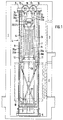
- the elevator according to the invention is for installation in an elevator shaft 1 determined in a building.
- the car is accessible from three sides.
- Fig. 1 are in the right shaft wall at 2 and 3rd Openings for side doors indicated; similar openings can also be formed in the right and front walls his.
- Fig. 1 there are only two for a better overview Shown floors on which the construction according to the invention but is not limited.
- the frame 4 On the rear wall of the elevator shaft 1 attached, in or on which the car and the counterweight be performed.
- the frame 4 consists of a lower one Cross member 5, an upper cross member 6 and right and left vertical guide rails 7, 8. Further reinforcement and stabilizing parts are not shown or figured.
- a console 9 is guided vertically, on the lower part protruding into the shaft cross-section Car 10 is placed and fixed in Fig. 1 for better overview is only indicated by dashed lines.
- the frame 4 and the console 9 can be a prefabricated Form a structural unit that as a whole or, for larger heads, installed in fittings in an existing pull-out shaft becomes.
- the console 9 consists of a guide part forming vertical frame and attachments attached to it protrude backwards into the frame 4 and on the guide rails 7, 8 are performed.
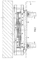
- Fig. 2 is the top right approach with 11 and the upper left approach with 12.
- the frame 4 there are also two further guide rails 13, 14 at a smaller mutual distance than the guide rails 7, 8 arranged.
- the guide rails 13, 14 serve to guide a counterweight 15.
- the opposite movement of the console 9 with the car 10 and the counterweight 15 is done by a cable.
- the Cable pull consists in the embodiment described here from four single ropes, but more or less can Ropes are present. It just has to be a straight one Act number.
- the pulley has four rollers, each of which is used for deflection of two single ropes and two for this purpose Has rope grooves.
- the axes 17 and 19 are parallel to each other, their distance and the diameter of the rollers 16 and 18 is dimensioned so that the roles do not overlap.
- the rollers 16 and 18 in the Depth direction of the elevator shaft 1 offset from each other.
- rollers 20 and 21 are on top of the counterweight 15 mounted on a common axis 22 and freely rotatable independently.
- the axis 22 runs parallel to axes 17 and 19, and rollers 20 and 21 are arranged such that the (front) roller 20 in one Level with the left roller 18 on the upper cross member 6 and the (rear) roller 21 in one plane with the right roller 16 lies.
- the cables 25a, 25b attached to the flange 23 go to the on the counterweight i5 roll 20 lying in front and loop around this in the lower area at an angle of about 180 ° from right to left.
- the ropes run from the reel 20 25a, 25b side by side to the left upper roller 18, over which are led from right to left. Then run the ropes 25a, 25b down to the neck 12 of the Console 9 and are set there.
- the other pair of cables 26a, 26b is correspondingly symmetrical from the flange 24 via the rollers 21 and 16 to the Approach 11.
- this system is a pulley system with two rolls, one loose and one fixed, of where the loose roller takes up twice the load halfway. To achieve a static balance of forces therefore the counterweight 15 be twice as heavy as the console 9 with the car 10.
- the ropes 25a, 25b, and 26a, 26b engage symmetrically on the sides of the console carrying the car 10 9 so that even when the load is uneven Car no lateral tilting forces can arise.
- the ropes run over their entire length and over the whole range of motion parallel to each other and in one Plane within the cross-section occupied by the frame 4, whereby the remaining cross-sectional area of the shaft can be used without restriction for the car.
Landscapes
- Engineering & Computer Science (AREA)
- Structural Engineering (AREA)
- Civil Engineering (AREA)
- Mechanical Engineering (AREA)
- Automation & Control Theory (AREA)
- Lift-Guide Devices, And Elevator Ropes And Cables (AREA)
- Types And Forms Of Lifts (AREA)
- Body Structure For Vehicles (AREA)
- Forklifts And Lifting Vehicles (AREA)
- Cage And Drive Apparatuses For Elevators (AREA)
Description
- Fig. 1
- eine schematische Ansicht des Aufzuges von vorn,
- Fig. 2
- eine Aufsicht auf das Gestell von oben.
- 1
- Aufzugschacht
- 2
- Türöffnung
- 3
- Türöffnung
- 4
- Gestell
- 5
- Unterer Querträger
- 6
- Oberer Querträger
- 7
- Rechte Führungsschiene
- 8
- Linke Führungsschiene
- 9
- Konsole
- 10
- Fahrkorb
- 11
- Rechter oberer Ansatz
- 12
- Linker oberer Ansatz
- 13
- Rechte Führungsschiene
- 14
- Linke Führungsschiene
- 15
- Gegengewicht
- 16
- Rechte Rolle
- 17
- Achse
- 18
- Linke Rolle
- 19
- Achse
- 20
- Rolle
- 21
- Rolle
- 22
- Achse
- 23
- Flansch
- 24
- Flansch
- 25a,b
- Seile
- 26a,b
- Seile
- 27
- Hydraulikzylinder
- 28
- Kolbenstange
Claims (9)
- Aufzug mit einem an einem Gestell (4) rucksackgeführten Fahrkorb (10), einem zwischen den Fahrkorbführungsschienen (7, 8) geführten Gegengewicht (15) und einem Seilzug, dessen Seile (25a, 25b, 26a, 26b) mit einem Ende im oberen Bereich des Aufzugschachtes (1) festgelegt sind, um eine auf das Gegengewicht aufgesetzte Rolle und eine weitere, an einem oberen Querträger (6) des Gestells festgelegte Rolle laufen und mit dem anderen Ende an einem Führungsteil des Fahrkorbs angreifen, dadurch gekennzeichnet, daß auf dem Gegengewicht (15) zwei gleichachsige Rollen (20, 21) und an dem oberen Querträger (6) zwei achsparallele Rollen (16, 18) nebeneinander angeordnet sind, daß eine gleiche Anzahl von Seilen um je eine Rolle auf dem Gegengewicht und an dem Querträger geführt ist, und daß die an dem Führungsteil des Fahrkorbs angreifenden Seilenden symmetrisch zur Mittellängsebene des Fahrkorbs (10) an den seitlichen Enden des Führungsteils festgelegt sind.
- Aufzug nach Anspruch 1, dadurch gekennzeichnet, daß der Fahrkorb (10) auf eine in dem Gestell (4) geführte Konsole (9) aufgesetzt ist und daß die Enden der Seile an dem in dem Gestell geführten Führungsteil (11, 12) der Konsole festgelegt sind.
- Aufzug nach Anspruch 1 oder 2, dadurch gekennzeichnet, daß alle Seile des Seilzugs in einer Ebene innerhalb des Gestells (4) verlaufen.
- Aufzug nach einem der Ansprüche 1 bis 3, dadurch gekennzeichnet, daß die Seile im oberen Bereich des Aufzugschachtes (1) an dem die Rollen (16, 18) tragenden Querträger (6) unterhalb der Rollen festgelegt sind.
- Aufzug nach Anspruch 4, dadurch gekennzeichnet, daß in Blickrichtung von der Seite des Fahrkorbs (10) auf das Gestell (4) hin gesehen die unter der rechten Rolle (16) auf dem oberen Querträger (6) festgelegten Seile (25a, 25b) von rechts nach links um die Rolle (20) auf dem Gegengewicht (15) verlaufen, von dort über linke Rolle (18) auf dem oberen Querträger (6) von rechts nach links geführt sind und dann nach unten zu einem Ansatz (12) an dem linken Enden des Führungsteils gehen, an dem sie mit den anderen Enden befestigt sind, und daß die unter der linken Rolle (18) auf dem oberen Querträger (6) festgelegten Seile (26a, 26b) entsprechend seitensymmtrisch verlaufen.
- Aufzug nach einem der Ansprüche 1 bis 5, dadurch gekennzeichnet, daß die Rollen (16, 18) auf dem oberen Querträger (6) einen solchen Durchmesser und einen solchen Achsabstand aufweisen, daß sie sich nicht überlappen.
- Aufzug nach einem der Ansprüche 1 bis 6, dadurch gekennzeichnet, daß das Gegengewicht (15) weniger als doppelt so schwer ist wie der Fahrkorb (10) und ggfs. die Konsole (9), und daß an das Gegengewicht von unten die Kolbenstange (28) eines Hydraulikzugzylinders (27) angreift.
- Aufzug nach einem der Ansprüche 1 bis 6, dadurch gekennzeichnet, daß ein die Rollen (16, 18) auf dem oberen Querträger (6) gegenläufig bewegender Antrieb vorgesehen ist.
- Aufzug nach einem der Ansprüche 1 bis 6, dadurch gekennzeichnet, daß die Rollen (20, 21) auf dem Gegengewicht (15) angetrieben sind.
Priority Applications (1)
| Application Number | Priority Date | Filing Date | Title |
|---|---|---|---|
| DE29522244U DE29522244U1 (de) | 1994-10-10 | 1995-09-27 | Aufzug mit einem an einem Gestell rucksackartig geführten Fahrkorb |
Applications Claiming Priority (2)
| Application Number | Priority Date | Filing Date | Title |
|---|---|---|---|
| DE4436088A DE4436088B4 (de) | 1994-10-10 | 1994-10-10 | Aufzug mit einem an einem Gestell rucksackgeführtem Fahrkorb |
| DE4436088 | 1994-10-10 |
Publications (3)
| Publication Number | Publication Date |
|---|---|
| EP0706969A2 EP0706969A2 (de) | 1996-04-17 |
| EP0706969A3 EP0706969A3 (de) | 1997-01-08 |
| EP0706969B1 true EP0706969B1 (de) | 2000-06-21 |
Family
ID=6530338
Family Applications (1)
| Application Number | Title | Priority Date | Filing Date |
|---|---|---|---|
| EP95115252A Expired - Lifetime EP0706969B1 (de) | 1994-10-10 | 1995-09-27 | Aufzug mit einem an einem Gestell rucksackgeführtem Fahrkorb |
Country Status (8)
| Country | Link |
|---|---|
| US (1) | US5788017A (de) |
| EP (1) | EP0706969B1 (de) |
| CN (1) | CN1053426C (de) |
| AT (1) | ATE193997T1 (de) |
| DE (2) | DE4436088B4 (de) |
| ES (1) | ES2148391T3 (de) |
| GR (1) | GR3034307T3 (de) |
| PT (1) | PT706969E (de) |
Cited By (1)
| Publication number | Priority date | Publication date | Assignee | Title |
|---|---|---|---|---|
| DE10319731B4 (de) * | 2003-04-30 | 2005-06-02 | Wittur Ag | Aufzug |
Families Citing this family (7)
| Publication number | Priority date | Publication date | Assignee | Title |
|---|---|---|---|---|
| DE19827497B4 (de) * | 1997-06-19 | 2005-02-17 | Wittur Ag | Aufzug |
| US6848543B2 (en) * | 1998-10-30 | 2005-02-01 | Otis Elevator Company | Single wall interface traction elevator |
| SG134994A1 (en) * | 2002-10-29 | 2007-09-28 | Inventio Ag | Lift counterweight |
| DE102005047499A1 (de) * | 2005-10-04 | 2007-04-12 | Wittur Ag | Aufzug (Rucksackaufzug mit am Fahrkorbrahmen aufgehängter Kabine) |
| FI120091B (fi) * | 2006-11-10 | 2009-06-30 | Kone Corp | Vastapainoton vetopyörähissi |
| US20100126807A1 (en) * | 2008-11-22 | 2010-05-27 | Tien-Tzu Liao | Screw elevator |
| DE102012100791A1 (de) | 2012-01-31 | 2013-08-01 | ThyssenKrupp Fördertechnik GmbH | Zugmittel-Windenvorrichtung |
Family Cites Families (6)
| Publication number | Priority date | Publication date | Assignee | Title |
|---|---|---|---|---|
| US1730974A (en) * | 1928-12-11 | 1929-10-08 | Atlantic Elevator Company Inc | Elevator suspension |
| US1837643A (en) * | 1931-03-28 | 1931-12-22 | Otis Elevator Co | Elevator system |
| US3845842A (en) * | 1973-06-13 | 1974-11-05 | W Johnson | Elevator system |
| JPS63106289A (ja) * | 1986-10-22 | 1988-05-11 | 株式会社日立製作所 | 流体圧エレベ−タ |
| DE4131668C1 (de) * | 1991-09-23 | 1993-02-18 | Leistritz Ag, 8500 Nuernberg, De | |
| IT1270505B (it) * | 1993-06-25 | 1997-05-06 | Palmieri & C Co Mac | Elevatore-traslatore idraulico e procedimento di elevazione- traslazione |
-
1994
- 1994-10-10 DE DE4436088A patent/DE4436088B4/de not_active Expired - Fee Related
-
1995
- 1995-09-27 EP EP95115252A patent/EP0706969B1/de not_active Expired - Lifetime
- 1995-09-27 DE DE59508486T patent/DE59508486D1/de not_active Expired - Fee Related
- 1995-09-27 ES ES95115252T patent/ES2148391T3/es not_active Expired - Lifetime
- 1995-09-27 AT AT95115252T patent/ATE193997T1/de not_active IP Right Cessation
- 1995-09-27 PT PT95115252T patent/PT706969E/pt unknown
- 1995-10-06 US US08/539,980 patent/US5788017A/en not_active Expired - Fee Related
- 1995-10-10 CN CN95119918A patent/CN1053426C/zh not_active Expired - Fee Related
-
2000
- 2000-08-31 GR GR20000401994T patent/GR3034307T3/el not_active IP Right Cessation
Cited By (1)
| Publication number | Priority date | Publication date | Assignee | Title |
|---|---|---|---|---|
| DE10319731B4 (de) * | 2003-04-30 | 2005-06-02 | Wittur Ag | Aufzug |
Also Published As
| Publication number | Publication date |
|---|---|
| DE4436088A1 (de) | 1996-04-11 |
| CN1053426C (zh) | 2000-06-14 |
| US5788017A (en) | 1998-08-04 |
| EP0706969A2 (de) | 1996-04-17 |
| DE4436088B4 (de) | 2005-06-16 |
| GR3034307T3 (en) | 2000-12-29 |
| EP0706969A3 (de) | 1997-01-08 |
| PT706969E (pt) | 2000-12-29 |
| ATE193997T1 (de) | 2000-07-15 |
| ES2148391T3 (es) | 2000-10-16 |
| CN1130149A (zh) | 1996-09-04 |
| DE59508486D1 (de) | 2000-07-27 |
Similar Documents
| Publication | Publication Date | Title |
|---|---|---|
| DE60007512T2 (de) | Treibscheibenaufzug | |
| DE69918218T2 (de) | Gezogener Aufzug | |
| EP1149795B1 (de) | Anordnung des Antriebsmodules eines Aufzugs | |
| EP2210849B1 (de) | Doppelkettenzuganordnung | |
| LU86532A1 (de) | Teleskopsaeule | |
| EP1935827B1 (de) | Aufzugssystem | |
| DE2457864C2 (de) | Laufkatzenkran | |
| DE69324124T2 (de) | Regalbedienungsgerät | |
| DE1781441A1 (de) | Laufkran | |
| EP0761582A2 (de) | Vertikaler Bandspeicher | |
| EP1302431A1 (de) | Seilaufzugsystem mit zwei Fahrkörben mit gemeinsamen und getrennten Farhbahnabschnitten | |
| DE1091279B (de) | Hoehenverstellbare Deckenaufhaengung mit Gewichtsausgleich | |
| DE4436088B4 (de) | Aufzug mit einem an einem Gestell rucksackgeführtem Fahrkorb | |
| DE3312174A1 (de) | Laufkatzen-seilhubwerk mit pendeldaempfung | |
| DE102012100791A1 (de) | Zugmittel-Windenvorrichtung | |
| AT509458B1 (de) | Regallager mit regalbediengerät | |
| DE10319731B4 (de) | Aufzug | |
| DE3035784C2 (de) | Hubbalken mit an einer Hängebahn verfahrbaren Laufwerken | |
| DE19650997C2 (de) | Vertikaler Bandspeicher | |
| DE19963286B4 (de) | Aufzug | |
| EP4344430B1 (de) | Maschinenraumloses aufzugssystem | |
| AT528592B1 (de) | Transporteinrichtung | |
| DE29522244U1 (de) | Aufzug mit einem an einem Gestell rucksackartig geführten Fahrkorb | |
| AT410784B (de) | Aufzug | |
| DE8508047U1 (de) | Hebegerät |
Legal Events
| Date | Code | Title | Description |
|---|---|---|---|
| PUAI | Public reference made under article 153(3) epc to a published international application that has entered the european phase |
Free format text: ORIGINAL CODE: 0009012 |
|
| AK | Designated contracting states |
Kind code of ref document: A2 Designated state(s): AT BE CH DE ES FR GB GR IT LI NL PT SE |
|
| PUAL | Search report despatched |
Free format text: ORIGINAL CODE: 0009013 |
|
| AK | Designated contracting states |
Kind code of ref document: A3 Designated state(s): AT BE CH DE ES FR GB GR IT LI NL PT SE |
|
| 17P | Request for examination filed |
Effective date: 19961218 |
|
| GRAG | Despatch of communication of intention to grant |
Free format text: ORIGINAL CODE: EPIDOS AGRA |
|
| 17Q | First examination report despatched |
Effective date: 19990810 |
|
| GRAG | Despatch of communication of intention to grant |
Free format text: ORIGINAL CODE: EPIDOS AGRA |
|
| GRAH | Despatch of communication of intention to grant a patent |
Free format text: ORIGINAL CODE: EPIDOS IGRA |
|
| GRAH | Despatch of communication of intention to grant a patent |
Free format text: ORIGINAL CODE: EPIDOS IGRA |
|
| GRAA | (expected) grant |
Free format text: ORIGINAL CODE: 0009210 |
|
| RAP1 | Party data changed (applicant data changed or rights of an application transferred) |
Owner name: WITTUR AG |
|
| AK | Designated contracting states |
Kind code of ref document: B1 Designated state(s): AT BE CH DE ES FR GB GR IT LI NL PT SE |
|
| REF | Corresponds to: |
Ref document number: 193997 Country of ref document: AT Date of ref document: 20000715 Kind code of ref document: T |
|
| REG | Reference to a national code |
Ref country code: CH Ref legal event code: EP |
|
| REF | Corresponds to: |
Ref document number: 59508486 Country of ref document: DE Date of ref document: 20000727 |
|
| REG | Reference to a national code |
Ref country code: CH Ref legal event code: NV Representative=s name: TROESCH SCHEIDEGGER WERNER AG |
|
| ITF | It: translation for a ep patent filed | ||
| ET | Fr: translation filed | ||
| GBT | Gb: translation of ep patent filed (gb section 77(6)(a)/1977) |
Effective date: 20000911 |
|
| REG | Reference to a national code |
Ref country code: ES Ref legal event code: FG2A Ref document number: 2148391 Country of ref document: ES Kind code of ref document: T3 |
|
| REG | Reference to a national code |
Ref country code: PT Ref legal event code: SC4A Free format text: AVAILABILITY OF NATIONAL TRANSLATION Effective date: 20000911 |
|
| PLBE | No opposition filed within time limit |
Free format text: ORIGINAL CODE: 0009261 |
|
| STAA | Information on the status of an ep patent application or granted ep patent |
Free format text: STATUS: NO OPPOSITION FILED WITHIN TIME LIMIT |
|
| 26N | No opposition filed | ||
| REG | Reference to a national code |
Ref country code: GB Ref legal event code: IF02 |
|
| PGFP | Annual fee paid to national office [announced via postgrant information from national office to epo] |
Ref country code: GB Payment date: 20030903 Year of fee payment: 9 |
|
| PGFP | Annual fee paid to national office [announced via postgrant information from national office to epo] |
Ref country code: NL Payment date: 20030917 Year of fee payment: 9 |
|
| PGFP | Annual fee paid to national office [announced via postgrant information from national office to epo] |
Ref country code: FR Payment date: 20030918 Year of fee payment: 9 |
|
| PGFP | Annual fee paid to national office [announced via postgrant information from national office to epo] |
Ref country code: BE Payment date: 20030922 Year of fee payment: 9 Ref country code: AT Payment date: 20030922 Year of fee payment: 9 |
|
| PGFP | Annual fee paid to national office [announced via postgrant information from national office to epo] |
Ref country code: SE Payment date: 20030923 Year of fee payment: 9 Ref country code: CH Payment date: 20030923 Year of fee payment: 9 |
|
| PGFP | Annual fee paid to national office [announced via postgrant information from national office to epo] |
Ref country code: PT Payment date: 20030924 Year of fee payment: 9 Ref country code: ES Payment date: 20030924 Year of fee payment: 9 |
|
| PGFP | Annual fee paid to national office [announced via postgrant information from national office to epo] |
Ref country code: GR Payment date: 20030930 Year of fee payment: 9 |
|
| PGFP | Annual fee paid to national office [announced via postgrant information from national office to epo] |
Ref country code: DE Payment date: 20031125 Year of fee payment: 9 |
|
| PG25 | Lapsed in a contracting state [announced via postgrant information from national office to epo] |
Ref country code: GB Free format text: LAPSE BECAUSE OF NON-PAYMENT OF DUE FEES Effective date: 20040927 Ref country code: AT Free format text: LAPSE BECAUSE OF NON-PAYMENT OF DUE FEES Effective date: 20040927 |
|
| PG25 | Lapsed in a contracting state [announced via postgrant information from national office to epo] |
Ref country code: SE Free format text: LAPSE BECAUSE OF NON-PAYMENT OF DUE FEES Effective date: 20040928 Ref country code: ES Free format text: LAPSE BECAUSE OF NON-PAYMENT OF DUE FEES Effective date: 20040928 |
|
| PG25 | Lapsed in a contracting state [announced via postgrant information from national office to epo] |
Ref country code: LI Free format text: LAPSE BECAUSE OF NON-PAYMENT OF DUE FEES Effective date: 20040930 Ref country code: CH Free format text: LAPSE BECAUSE OF NON-PAYMENT OF DUE FEES Effective date: 20040930 Ref country code: BE Free format text: LAPSE BECAUSE OF NON-PAYMENT OF DUE FEES Effective date: 20040930 |
|
| PG25 | Lapsed in a contracting state [announced via postgrant information from national office to epo] |
Ref country code: PT Free format text: LAPSE BECAUSE OF NON-PAYMENT OF DUE FEES Effective date: 20050328 |
|
| BERE | Be: lapsed |
Owner name: *WITTUR A.G. Effective date: 20040930 |
|
| PG25 | Lapsed in a contracting state [announced via postgrant information from national office to epo] |
Ref country code: NL Free format text: LAPSE BECAUSE OF NON-PAYMENT OF DUE FEES Effective date: 20050401 Ref country code: DE Free format text: LAPSE BECAUSE OF NON-PAYMENT OF DUE FEES Effective date: 20050401 |
|
| PG25 | Lapsed in a contracting state [announced via postgrant information from national office to epo] |
Ref country code: GR Free format text: LAPSE BECAUSE OF NON-PAYMENT OF DUE FEES Effective date: 20050405 |
|
| EUG | Se: european patent has lapsed | ||
| REG | Reference to a national code |
Ref country code: CH Ref legal event code: PL |
|
| GBPC | Gb: european patent ceased through non-payment of renewal fee |
Effective date: 20040927 |
|
| PG25 | Lapsed in a contracting state [announced via postgrant information from national office to epo] |
Ref country code: FR Free format text: LAPSE BECAUSE OF NON-PAYMENT OF DUE FEES Effective date: 20050531 |
|
| REG | Reference to a national code |
Ref country code: PT Ref legal event code: MM4A Free format text: LAPSE DUE TO NON-PAYMENT OF FEES Effective date: 20050328 |
|
| NLV4 | Nl: lapsed or anulled due to non-payment of the annual fee |
Effective date: 20050401 |
|
| REG | Reference to a national code |
Ref country code: FR Ref legal event code: ST |
|
| PG25 | Lapsed in a contracting state [announced via postgrant information from national office to epo] |
Ref country code: IT Free format text: LAPSE BECAUSE OF NON-PAYMENT OF DUE FEES;WARNING: LAPSES OF ITALIAN PATENTS WITH EFFECTIVE DATE BEFORE 2007 MAY HAVE OCCURRED AT ANY TIME BEFORE 2007. THE CORRECT EFFECTIVE DATE MAY BE DIFFERENT FROM THE ONE RECORDED. Effective date: 20050927 |
|
| REG | Reference to a national code |
Ref country code: ES Ref legal event code: FD2A Effective date: 20040928 |
|
| BERE | Be: lapsed |
Owner name: *WITTUR A.G. Effective date: 20040930 |