EP0704682A2 - Magnetisch-induktiver Durchflussmesser für Freispiegelflüssigkeitsleitung - Google Patents
Magnetisch-induktiver Durchflussmesser für Freispiegelflüssigkeitsleitung Download PDFInfo
- Publication number
- EP0704682A2 EP0704682A2 EP95116484A EP95116484A EP0704682A2 EP 0704682 A2 EP0704682 A2 EP 0704682A2 EP 95116484 A EP95116484 A EP 95116484A EP 95116484 A EP95116484 A EP 95116484A EP 0704682 A2 EP0704682 A2 EP 0704682A2
- Authority
- EP
- European Patent Office
- Prior art keywords
- conduit
- fluid
- flow rate
- measuring
- relationship
- Prior art date
- Legal status (The legal status is an assumption and is not a legal conclusion. Google has not performed a legal analysis and makes no representation as to the accuracy of the status listed.)
- Granted
Links
Images


Classifications
-
- G—PHYSICS
- G01—MEASURING; TESTING
- G01F—MEASURING VOLUME, VOLUME FLOW, MASS FLOW OR LIQUID LEVEL; METERING BY VOLUME
- G01F1/00—Measuring the volume flow or mass flow of fluid or fluent solid material wherein the fluid passes through a meter in a continuous flow
- G01F1/002—Measuring the volume flow or mass flow of fluid or fluent solid material wherein the fluid passes through a meter in a continuous flow wherein the flow is in an open channel
-
- G—PHYSICS
- G01—MEASURING; TESTING
- G01F—MEASURING VOLUME, VOLUME FLOW, MASS FLOW OR LIQUID LEVEL; METERING BY VOLUME
- G01F1/00—Measuring the volume flow or mass flow of fluid or fluent solid material wherein the fluid passes through a meter in a continuous flow
- G01F1/56—Measuring the volume flow or mass flow of fluid or fluent solid material wherein the fluid passes through a meter in a continuous flow by using electric or magnetic effects
- G01F1/58—Measuring the volume flow or mass flow of fluid or fluent solid material wherein the fluid passes through a meter in a continuous flow by using electric or magnetic effects by electromagnetic flowmeters
- G01F1/586—Measuring the volume flow or mass flow of fluid or fluent solid material wherein the fluid passes through a meter in a continuous flow by using electric or magnetic effects by electromagnetic flowmeters constructions of coils, magnetic circuits, accessories therefor
-
- G—PHYSICS
- G01—MEASURING; TESTING
- G01F—MEASURING VOLUME, VOLUME FLOW, MASS FLOW OR LIQUID LEVEL; METERING BY VOLUME
- G01F1/00—Measuring the volume flow or mass flow of fluid or fluent solid material wherein the fluid passes through a meter in a continuous flow
- G01F1/56—Measuring the volume flow or mass flow of fluid or fluent solid material wherein the fluid passes through a meter in a continuous flow by using electric or magnetic effects
- G01F1/58—Measuring the volume flow or mass flow of fluid or fluent solid material wherein the fluid passes through a meter in a continuous flow by using electric or magnetic effects by electromagnetic flowmeters
- G01F1/60—Circuits therefor
-
- G—PHYSICS
- G01—MEASURING; TESTING
- G01F—MEASURING VOLUME, VOLUME FLOW, MASS FLOW OR LIQUID LEVEL; METERING BY VOLUME
- G01F25/00—Testing or calibration of apparatus for measuring volume, volume flow or liquid level or for metering by volume
- G01F25/10—Testing or calibration of apparatus for measuring volume, volume flow or liquid level or for metering by volume of flowmeters
- G01F25/13—Testing or calibration of apparatus for measuring volume, volume flow or liquid level or for metering by volume of flowmeters using a reference counter
Definitions
- the present invention relates to an electromagnetic flowmeter for an unfilled fluid flow conduit.
- JP-A-52-48356 an arrangement in which the coils disposed above and below a flow conduit are connected in series to each other is disclosed in JP-A-52-48356.
- the applicant now proposes a flow rate measuring method for measuring a flow rate of a fluid flowing through a flow conduit in the unfilled state thereof on the basis of the principle underlying an electromagnetic flowmeter and a flow rate detector used in carrying out the aforementioned method.
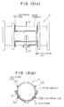
- a numeral 1 denotes a flow conduit having a circular cross-section
- 2 denote a pair of electrodes disposed at positions symmetrical to a vertical line extending through the center of the flow conduit 1
- 3A and 3B denote first and second excitation coils for generating magnetic flux density distributions BA and BB differing from each other for different periods (or times).
- a reference symbol 4 designates generally a flow rate detector of the illustrated structure.
- a numeral 5 denotes an excitation circuit which responds to a signal outputted from a timing circuit 6 to excite the first and second excitation coils 3A and 3B alternately with each other.
- a numeral 7 denotes a preamplifier for amplifying a voltage making appearance across the electrodes 2;2, a symbol S1 denotes a change-over switch which operates in response to the signal supplied from the timing circuit 6 to change over the paired excitation coils 3A and 3B mentioned above in synchronism with the change-over of the aforementioned excitation periods. More specifically, the switch S1 is changed-over to a contact a when the first excitation coil 3A is excited, while being changed over to a contact b when the second excitation coil 3B is excited.
- Reference symbols 8A and 8B denote amplifiers which are supplied with signals via the contact a and the contact b , respectively, and serve for an offset compensation and a sample and hold function of these signals
- a numeral 9 denotes a CPU circuit
- a numeral 10 denotes an A/D conversion circuit for converting the analogue signals supplied from the amplifiers 8A; 8B to digital signals
- a numeral 11 denotes an arithmetic circuit incorporating a program for performing arithmetic operations which will be described later on.
- a reference numeral 12 denotes an output terminal for outputting a flow rate signal generated as a result of the arithmetic operation.
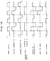
- Figure 14 is a timing chart for illustrating operation of the electromagnetic flowmeter of the structure shown in Figure 12 and shows from the top of the figure an output signal of the timing circuit 5, an exciting current for the first excitation coil 3A, an exciting current for the second excitation coil 3B, operation of the change-over switch S1, an output signal of the preamplifier 7, an input signal to the amplification circuit 8A and an input signal to the amplification circuit 8B, respectively, in this order.
- Step 1 A flow conduit having the same cross-sectional shape as the flow conduit 1 for which the flow rate is to be measured is provided.
- output signals OA and OB corresponding to flow rates Q at the above-mentioned fluid levels are previously determined.
- the fluid level and the flow rate boar a one-to-one correspondence to each other.
- the output signals OA and OB represent flow rate signals generated by the first and second excitation coils 3A and 3B, respectively, when the same flow rate Q is measured by using the flow rate detector 4 operating in accordance with the principle underlying the electromagnetic flowmeter (Fig 15(a)).
- Step 2 Unknown flow rate Q' in the flow conduit 1 through which a fluid whose flow rate is to be measured is flowing is measured by means of the aforementioned flow detector 4 to obtain output data OA' and OB'.
- Step 3 A ratio OB'/OA' between the outputs OB' and OA' is determined, and then a flow rate Q ⁇ for which a ratio OB/OA between the outputs OB and OA determined in the step 1 assumes the same value as the ratio OB'/OA' is retrieved from the data obtained in the step 1 ( Figure 15(b)(c)), whereon a sensitivity given by OA ⁇ /Q ⁇ in the state where the flow rate in the step 1 is Q ⁇ is arithmetically determined from the output data OA ⁇ acquired in the step 1 when the flow rate is Q ⁇ ( Figure 15(d)).
- Figure 16 shows a general arrangement of an apparatus employed in the experiments for verifying the measurement accuracy afforded by the above-mentioned measuring method, wherein the flow rate detector 4 described above by reference to Figures 12 and 13 is mounted on a pipe 13 made of vinyl chloride and having an inner diameter of 200 mm and a length of about 8 m.
- the slope of this vinyl chloride pipe was first set fixedly at 2/1000, and an actual flow rate Q was measured by using the first excitation coil 3A.
- a relation between this actual flow rate Q and the output OA of the electromagnetic flowmeter is representated by a curve OA in Figure 17.
- a curve OB represents result of the measurement carried out by using the second excitation coil 3B at the same slope of the pipe.
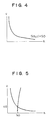
- Ratios OB/OA determined from both data OA and OB shown in Figure 17 are shown in Figure 18.
- the ratio OB/OA remains constant at a minimum value when the flow rate exceeds a value of approximately 100 [m3/hour].
- This range represents a so-called completely filled state.
- the curves OA and OB constitute line segments of straight lines extending through the origin of the coordinate system in a range where the flow rate Q is greater than about 100 [m3/hour].
- the above-mentioned range indicates a range in which the electromagnetic flowmeter operates as a so-called conventional full-fluid type electromagnetic flowmeter.
- Figure 19 shows relationships between an actual flow rate Q' [m3/hour] measured by using the apparatus shorn in Figure 16 and by changing the slope of the flow conduit 13 to 6/1000 and the outputs OA' and OB' obtained by exciting the excitation coils 3A and 3B, respectively.
- the actual flow shown in Figure 19 is known.
- instrumentation-ascribable errors were determined at several values of the flow rate Q'. The errors were of relatively small values, as shown in Figure 20. The practicality of this measuring method could thus be verified.
- the flow rate measuring method elucidated in the aforegoing suffers from a problem that the measurement is accomplished with errors under the influence of conductivity of the fluid to be measured because symmetry is likely to be lost in the positional relationship between the electrodes of the flow rate detector 4 as used and the ground as well as in the relation between the electrode profile and the exciting magnetic flux density distribution.
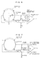
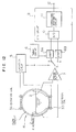
- the electromagnetic flowmeter for an unfilled fluid flow conduit proposed for achieving the above additional object is characterised in that it comprises a main body part 24 including an upper-side excitation coil (Cu) and a lower-side excitation coil (Cl) which can be excited separately from each other and a pair of electrodes 22 disposed in opposition to each other, and a transducer part 32 which includes requirements (a) to (g) mentioned below.
- the arithmetic processing circuit 31 may be so configured as to produce a conductivity output by processing the output from the A/D conversion circuit 30.
- Figure 2 shows a timing chart for one typical cycle of measurement.
- One measurement cycle illustrated consists of periods a to f . In the first place, description will briefly be made of individual signals.
- Figure 1(a) is a block diagram showing an apparatus according to the invention and Figure 1(b) is a view showing a part of the same in detail.
- Figure 2 is a timing chart.
- Figure 3 is a view showing a curve p , on a (h-c) plane.
- Figure 4 is a view showing a curve s on the (h-c) plane.
- Figure 5 is a view showing the curve p and the curve s on the (h-c) plane.
- Figure 6 shows a major portion of an electric circuit according to the present invention.
- Figure 7 shows an electric circuit of a major portion of an embodiment of the present invention.
- Figure 8 is a view showing a curve p on a (h-c) plane according to an embodiment of the invention.
- Figure 9 is a view showing a curve s on a (h-c) plane according to an embodiment of the invention.
- Figure 10 shows an instrumentation-attributable error curve in an exemplary one of the prior art techniques.
- Figure 11 shows an instrumentation-attributable error curve in an embodiment of the invention.
- Figure 12 is a block diagram showing an electromagnetic flowmeter according to a basic embodiment of the invention.
- Figure 13(a) shows a flow rate detector according to Figure 12 in a front side view and Figure 13(b) shows the same in a sectional view taken along a line A-A in Figure 13(a).
- Figure 14 is a timing chart for illustrating operation of the electromagnetic flowmeter shown in Figure 12.
- Figure 15(a) to Figure 15(d) are views for graphically illustrating procedures for carrying out a flow rate measuring method according to a basic embodiment of the invention, wherein Figure 15(a) graphically shows a flowmeter output, Figure 15(b) graphically shows a flowmeter output ratio, Figure 15(c) is a view for illustrating a procedure for determining a flow rate Q ⁇ at a same fluid level on the basis of an output ratio obtained from an unknown flow rate, and Figure 15(d) is a view for illustrating a procedure for determining sensitivity from the output curve OA.
- Figure 16 is a schematic view showing an experimental apparatus used in verification of the measurement accuracy of a technique according to Figure 15.
- Figure 17 is a view graphically showing, by way of example, relations between an actual flow rate Q and outputs OA and OB of a flow rate detector as shown in Figure 12.
- Figure 18 is a view graphically showing a relation between an actual flow rate Q and a ratio OB/OA arithmetically determined from the data shown in Figure 17.
- Figure 19 is a graphical view corresponding to Figure 17 in a case where the slope of a flow pipe is different.
- Figure 20 is an instrumentation-attributable error characteristic diagram of an apparatus as shown in Figure 12.
- Figure 21 is a flow chart for illustrating a method according to an embodiment of the present invention.
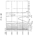
- Figure 22 is a view for graphically illustrating relations between g , h and c .
- a region where the fluid level h is higher than 1.0 D represents the case in which the fluid is transported under pressure in the filled state of the pipe. This region is plotted only for the purpose of reference.
- Figure 22 is a view for graphically illustrating relations between the ratio g ⁇ Q/Eu and the fluid level h and the conductivity c .
- the relations shown in Figure 22 as well as the relations shown in Figures 8 and 9 are previously stored in a memory incorporated in the arithmetic processing part 31.
- a step S1 the output Eu of the upper-side coil obtained when the shunt switch S2 is opened, the output Eu' of the same coil when the switch S2 is closed and the output El of the lower-side coil are detected and stored in registers incorporated in the arithmetic processing part 31.
- a step S7 the value of p0 obtained in the step S3 is compared with the data shown in Figure 8 and stored in the memory, to thereby select one of the data shown in Figure 8 which is closest to p0.
- the value of S0 obtained in step S5 is compared with the data of Figure 9 stored in the memory, to select one of the data which is closest to S0.
- step S9 data of Figure 22 stored in the memory are consulted to determine g0 from the fluid level h0 and the conductivity c0 determined in the step 7.
- step S11 the output Eu of the upper-side coil is read out from the register and is multiplied by the ratio g0 obtained in step S9 to determine arithmetically the actual flow rate Q0.
- the inner diameter of the pipe is 240 mm.
- Each of the electrodes 2 has a width of 40 mm in the flow direction and a thickness of 2 mm. Both electrodes are disposed with an intervening angle of 90°.
- the coils as used are each composed of a winding of 1300 turns.
Landscapes
- Physics & Mathematics (AREA)
- Fluid Mechanics (AREA)
- General Physics & Mathematics (AREA)
- Electromagnetism (AREA)
- Engineering & Computer Science (AREA)
- Power Engineering (AREA)
- Measuring Volume Flow (AREA)
Applications Claiming Priority (4)
| Application Number | Priority Date | Filing Date | Title |
|---|---|---|---|
| JP222939/91 | 1991-09-03 | ||
| JP22293991 | 1991-09-03 | ||
| JP22293991 | 1991-09-03 | ||
| EP92918706A EP0557529B1 (de) | 1991-09-03 | 1992-09-03 | Magnetisch induktiver freispiegeldurchflussmesser |
Related Parent Applications (2)
| Application Number | Title | Priority Date | Filing Date |
|---|---|---|---|
| EP92918706.0 Division | 1992-09-03 | ||
| EP92918706A Division EP0557529B1 (de) | 1991-09-03 | 1992-09-03 | Magnetisch induktiver freispiegeldurchflussmesser |
Publications (3)
| Publication Number | Publication Date |
|---|---|
| EP0704682A2 true EP0704682A2 (de) | 1996-04-03 |
| EP0704682A3 EP0704682A3 (de) | 1996-07-03 |
| EP0704682B1 EP0704682B1 (de) | 2002-06-05 |
Family
ID=16790243
Family Applications (2)
| Application Number | Title | Priority Date | Filing Date |
|---|---|---|---|
| EP95116484A Expired - Lifetime EP0704682B1 (de) | 1991-09-03 | 1992-09-03 | Magnetisch-induktiver Durchflussmesser für Freispiegelflüssigkeitsleitung |
| EP92918706A Expired - Lifetime EP0557529B1 (de) | 1991-09-03 | 1992-09-03 | Magnetisch induktiver freispiegeldurchflussmesser |
Family Applications After (1)
| Application Number | Title | Priority Date | Filing Date |
|---|---|---|---|
| EP92918706A Expired - Lifetime EP0557529B1 (de) | 1991-09-03 | 1992-09-03 | Magnetisch induktiver freispiegeldurchflussmesser |
Country Status (3)
| Country | Link |
|---|---|
| EP (2) | EP0704682B1 (de) |
| DE (2) | DE69216381T2 (de) |
| WO (1) | WO1993005367A1 (de) |
Cited By (14)
| Publication number | Priority date | Publication date | Assignee | Title |
|---|---|---|---|---|
| EP2821756A1 (de) | 2013-07-01 | 2015-01-07 | Krohne Messtechnik GmbH | Magnetisch-induktives Durchflussmessgerät und Verfahren zum Betreiben eines magnetisch-induktiven Durchflussmessgeräts |
| DE102013013991A1 (de) | 2013-07-08 | 2015-01-08 | Krohne Messtechnik Gmbh | Magnetisch-induktives Durchflussmessgerät |
| DE102014015208A1 (de) | 2013-10-17 | 2015-04-23 | Krohne Ag | Magnetisch-induktives Durchflussmesssystem |
| DE102013019182A1 (de) | 2013-10-17 | 2015-05-07 | Krohne Ag | Messrohr für magnetisch-induktive Durchflussmesssysteme |
| DE102015116672A1 (de) | 2015-01-05 | 2016-07-07 | Krohne Ag | Durchflussmessgerät |
| EP3043153A1 (de) | 2015-01-05 | 2016-07-13 | Krohne AG | Durchflussmessgerät |
| DE102015116674A1 (de) | 2015-01-14 | 2016-07-14 | Krohne Ag | Magnetisch-induktives Durchflussmessgerät |
| DE102015116675A1 (de) | 2015-01-13 | 2016-07-14 | Krohne Ag | Magnetisch-induktives Durchflussmessgerät |
| DE102015116673A1 (de) | 2015-01-13 | 2016-07-14 | Krohne Ag | Magnetisch-induktives Durchflussmessgerät |
| EP3045875A2 (de) | 2015-01-14 | 2016-07-20 | Krohne AG | Magnetisch-induktives durchflussmessgerät |
| EP3045874A2 (de) | 2015-01-14 | 2016-07-20 | Krohne AG | Magnetisch-induktives durchflussmessgerät |
| DE102015116676A1 (de) | 2015-01-20 | 2016-07-21 | Krohne Ag | Magnetisch-induktives Durchflussmessgerät und Verfahren zum Herstellen einer Messelektrode |
| EP3048431A2 (de) | 2015-01-20 | 2016-07-27 | Krohne AG | Magnetisch-induktives durchflussmessgerät und verfahren zur herstellung einer messelektrode |
| WO2018127735A1 (en) * | 2017-01-03 | 2018-07-12 | Abb Schweiz Ag | Electromagnetic flowmeter and method of operating the electromagnetic flowmeter for detecting flow of multiphase fluids |
Families Citing this family (14)
| Publication number | Priority date | Publication date | Assignee | Title |
|---|---|---|---|---|
| US5625155A (en) * | 1901-09-03 | 1997-04-29 | Aichi Tokei Denki Co., Ltd. | Electromagnetic flowmeter |
| US5524493A (en) * | 1991-09-03 | 1996-06-11 | Aichi Tokei Denki Co., Ltd. | Electromagnetic flowmeter |
| DE69216381T2 (de) * | 1991-09-03 | 1997-04-24 | Aichi Tokei Denki Kk | Magnetisch induktiver freispiegeldurchflussmesser |
| DE69221595T2 (de) * | 1991-12-18 | 1997-12-11 | Aichi Tokei Denki Kk | Elektromagnetischer Durchflussmesser |
| US5621177A (en) * | 1995-03-02 | 1997-04-15 | Yokogawa Electric Corporation | Electromagnetic flowmeter |
| JP3602636B2 (ja) * | 1996-02-26 | 2004-12-15 | 愛知時計電機株式会社 | 電磁流量計 |
| US5841824A (en) * | 1997-05-13 | 1998-11-24 | Westinghouse Electric Corporation | System and method for testing the free fall time of nuclear reactor control rods |
| GB2358064A (en) * | 2000-01-06 | 2001-07-11 | Abb Instrumentation Ltd | Flow meter structure |
| CN100387940C (zh) * | 2005-12-23 | 2008-05-14 | 李斌 | 非绝缘测量管的电磁流量传感器 |
| DE102007014469A1 (de) | 2007-03-22 | 2008-09-25 | Endress + Hauser Flowtec Ag | Verfahren zur vorausschauenden Wartung und/oder Verfahren zur Bestimmung der elektrischen Leitfähigkeit bei einem magnetischinduktiven Durchflussmessgerät |
| IT1391185B1 (it) * | 2008-07-24 | 2011-11-18 | Gate Srl | Procedimento per il rilevamento della corrente assorbita da un motore elettrico in corrente continua |
| RU2489684C1 (ru) * | 2011-12-26 | 2013-08-10 | Закрытое акционерное общество "Управляющая компания Холдинга "Теплоком" | Электромагнитный расходомер |
| CN104266698A (zh) * | 2014-10-22 | 2015-01-07 | 中山欧麦克仪器设备有限公司 | 一种微流量的智能型电磁流量计 |
| CN113188615B (zh) * | 2021-04-28 | 2022-04-29 | 西南石油大学 | 一种基于动态偏移补偿的电磁流量计系统及测量方法 |
Citations (2)
| Publication number | Priority date | Publication date | Assignee | Title |
|---|---|---|---|---|
| JPS5248356A (en) | 1975-10-14 | 1977-04-18 | Fischer & Porter Co | Electromagnetic flowmeter |
| JPS59230115A (ja) | 1983-06-11 | 1984-12-24 | Yamatake Honeywell Co Ltd | 電磁流量計 |
Family Cites Families (11)
| Publication number | Priority date | Publication date | Assignee | Title |
|---|---|---|---|---|
| JP2974478B2 (ja) * | 1991-01-22 | 1999-11-10 | 愛知時計電機株式会社 | 非満水状態での流量計測方法と、この方法に使う流量検出器及び電磁流量計 |
| NL7017343A (de) * | 1969-12-18 | 1971-06-22 | ||
| DE2063792C3 (de) * | 1970-12-24 | 1978-06-08 | Eckardt Ag, 7000 Stuttgart | Magnetische Abflußmeßeinrichtung |
| JPS62114317U (de) * | 1986-01-10 | 1987-07-21 | ||
| JPS636420A (ja) * | 1986-06-26 | 1988-01-12 | Fuji Electric Co Ltd | 電磁流量計の空水検知回路 |
| JPS6375620A (ja) * | 1986-09-19 | 1988-04-06 | Kensetsusho Doboku Kenkyu Shocho | 開水路の流量測定装置 |
| JP2568620B2 (ja) * | 1988-03-29 | 1997-01-08 | 愛知時計電機株式会社 | 電磁流量計 |
| JPH01292214A (ja) * | 1988-05-19 | 1989-11-24 | Aichi Tokei Denki Co Ltd | 電磁流量計 |
| EP0451308B1 (de) * | 1990-04-09 | 1995-03-01 | Fischer & Porter GmbH | Schaltungsanordnung zur Messung des Stroms einer elektrische Ladungen enthaltenden Flüssigkeit |
| DE69216381T2 (de) * | 1991-09-03 | 1997-04-24 | Aichi Tokei Denki Kk | Magnetisch induktiver freispiegeldurchflussmesser |
| WO1993005368A1 (en) * | 1991-09-03 | 1993-03-18 | Aichi Tokei Denki Co., Ltd. | Electromagnetic flowmeter for water conveyance in semifull state |
-
1992
- 1992-09-03 DE DE69216381T patent/DE69216381T2/de not_active Expired - Lifetime
- 1992-09-03 WO PCT/JP1992/001123 patent/WO1993005367A1/ja active IP Right Grant
- 1992-09-03 EP EP95116484A patent/EP0704682B1/de not_active Expired - Lifetime
- 1992-09-03 EP EP92918706A patent/EP0557529B1/de not_active Expired - Lifetime
- 1992-09-03 DE DE69232633T patent/DE69232633T2/de not_active Expired - Lifetime
Patent Citations (2)
| Publication number | Priority date | Publication date | Assignee | Title |
|---|---|---|---|---|
| JPS5248356A (en) | 1975-10-14 | 1977-04-18 | Fischer & Porter Co | Electromagnetic flowmeter |
| JPS59230115A (ja) | 1983-06-11 | 1984-12-24 | Yamatake Honeywell Co Ltd | 電磁流量計 |
Cited By (26)
| Publication number | Priority date | Publication date | Assignee | Title |
|---|---|---|---|---|
| US10712185B2 (en) | 2013-07-01 | 2020-07-14 | Krohne Messtechnik Gmbh | Magnetic-inductive flowmeter and method for operating a magnetic-inductive flowmeter |
| DE102014007426A1 (de) | 2013-07-01 | 2015-01-08 | Krohne Messtechnik Gmbh | Magnetisch-induktives Durchflussmessgerät und Verfahren zum Betreiben eines magnetisch-induktiven Druchflussmessgeräts |
| DE102014007426B4 (de) | 2013-07-01 | 2022-07-07 | Krohne Messtechnik Gmbh | Magnetisch-induktives Durchflussmessgerät und Verfahren zum Betreiben eines magnetisch-induktiven Durchflussmessgeräts |
| EP2821756A1 (de) | 2013-07-01 | 2015-01-07 | Krohne Messtechnik GmbH | Magnetisch-induktives Durchflussmessgerät und Verfahren zum Betreiben eines magnetisch-induktiven Durchflussmessgeräts |
| DE102013013991A1 (de) | 2013-07-08 | 2015-01-08 | Krohne Messtechnik Gmbh | Magnetisch-induktives Durchflussmessgerät |
| US9200933B2 (en) | 2013-07-08 | 2015-12-01 | Krohne Messtechnik Gmbh | Magneto-inductive flowmeter having a functional unit with a request initiator activated by a user or the flowmeter |
| DE102014015208A1 (de) | 2013-10-17 | 2015-04-23 | Krohne Ag | Magnetisch-induktives Durchflussmesssystem |
| DE102013019182A1 (de) | 2013-10-17 | 2015-05-07 | Krohne Ag | Messrohr für magnetisch-induktive Durchflussmesssysteme |
| US9534943B2 (en) | 2013-10-17 | 2017-01-03 | Krohne Ag | Measuring tube for magneto-inductive flow-measuring systems |
| US9766104B2 (en) | 2013-10-17 | 2017-09-19 | Krohne Ag | Magneto-inductive flow-measuring system |
| DE102015116672A1 (de) | 2015-01-05 | 2016-07-07 | Krohne Ag | Durchflussmessgerät |
| EP3043153A1 (de) | 2015-01-05 | 2016-07-13 | Krohne AG | Durchflussmessgerät |
| US9625301B2 (en) | 2015-01-05 | 2017-04-18 | Krohne Ag | Flowmeter |
| DE102015116673A1 (de) | 2015-01-13 | 2016-07-14 | Krohne Ag | Magnetisch-induktives Durchflussmessgerät |
| DE102015116675A1 (de) | 2015-01-13 | 2016-07-14 | Krohne Ag | Magnetisch-induktives Durchflussmessgerät |
| EP3045875A2 (de) | 2015-01-14 | 2016-07-20 | Krohne AG | Magnetisch-induktives durchflussmessgerät |
| US9689725B2 (en) | 2015-01-14 | 2017-06-27 | Krohne Ag | Magnetic-inductive flowmeter having a central flat measuring tube portion with support ribs |
| US9709426B2 (en) | 2015-01-14 | 2017-07-18 | Krohne Ag | Magnetic-inductive flowmeter |
| EP3045874A2 (de) | 2015-01-14 | 2016-07-20 | Krohne AG | Magnetisch-induktives durchflussmessgerät |
| DE102015116679A1 (de) | 2015-01-14 | 2016-07-14 | Krohne Ag | Magnetisch-induktives Durchflussmessgerät |
| DE102015116674B4 (de) | 2015-01-14 | 2021-08-19 | Krohne Ag | Magnetisch-induktives Durchflussmessgerät |
| DE102015116674A1 (de) | 2015-01-14 | 2016-07-14 | Krohne Ag | Magnetisch-induktives Durchflussmessgerät |
| EP3048431A2 (de) | 2015-01-20 | 2016-07-27 | Krohne AG | Magnetisch-induktives durchflussmessgerät und verfahren zur herstellung einer messelektrode |
| DE102015116676A1 (de) | 2015-01-20 | 2016-07-21 | Krohne Ag | Magnetisch-induktives Durchflussmessgerät und Verfahren zum Herstellen einer Messelektrode |
| US10118324B2 (en) | 2015-01-20 | 2018-11-06 | Krohne Ag | Magnetic-inductive flowmeter and method for producing a measuring electrode |
| WO2018127735A1 (en) * | 2017-01-03 | 2018-07-12 | Abb Schweiz Ag | Electromagnetic flowmeter and method of operating the electromagnetic flowmeter for detecting flow of multiphase fluids |
Also Published As
| Publication number | Publication date |
|---|---|
| DE69232633T2 (de) | 2002-09-19 |
| DE69216381T2 (de) | 1997-04-24 |
| EP0557529A4 (de) | 1994-02-16 |
| WO1993005367A1 (en) | 1993-03-18 |
| EP0704682A3 (de) | 1996-07-03 |
| DE69216381D1 (de) | 1997-02-13 |
| EP0557529A1 (de) | 1993-09-01 |
| EP0704682B1 (de) | 2002-06-05 |
| DE69232633D1 (de) | 2002-07-11 |
| EP0557529B1 (de) | 1997-01-02 |
Similar Documents
| Publication | Publication Date | Title |
|---|---|---|
| EP0704682A2 (de) | Magnetisch-induktiver Durchflussmesser für Freispiegelflüssigkeitsleitung | |
| KR100216646B1 (ko) | 전자유량계 | |
| US4408497A (en) | Electromagnetic flowmeter for measuring ferromagnetic slurries | |
| US5443552A (en) | Electromagnetic flowmeter and method for electromagnetically measuring flow rate | |
| US7219557B2 (en) | Method and apparatus for calculating flowing medium temperature in a magnetoinductive flowmeter | |
| EP0559350A1 (de) | Vorrichtung und Verfahren zur Feststellung einer unvollständigen Füllung | |
| EP0547751A2 (de) | Elektromagnetischer Durchflussmesser | |
| US5307688A (en) | Method and flowmeter for unsteady fluid flow study | |
| US5327787A (en) | Electromagnetic flow meter with weir | |
| US20230015365A1 (en) | Method for operating a magneto-inductive flowmeter, and magneto-inductive flowmeter | |
| US5625155A (en) | Electromagnetic flowmeter | |
| EP0555493B1 (de) | Magnetisch-induktiver durchflussmesser für wasserfreispiegelleitung | |
| US4118981A (en) | Flowmeter | |
| CA2390062A1 (en) | Electromagnetic flowmeter | |
| US5524493A (en) | Electromagnetic flowmeter | |
| US7110899B2 (en) | Phase measurement in measuring device | |
| KR101089275B1 (ko) | 비만관용 전자유량계 | |
| JP3337118B2 (ja) | 電磁流量計 | |
| US20030029250A1 (en) | Electromagnetic flowmeter | |
| JP3820052B2 (ja) | 電磁流量計 | |
| JP2945476B2 (ja) | 非満水用電磁流量計 | |
| JP2945475B2 (ja) | 非満水用電磁流量計 | |
| JP4112700B2 (ja) | 非満水電磁流量計 | |
| JPH05223605A (ja) | 非満水状態での流量計測方法と、この方法に使う流量検出 器及び電磁流量計 | |
| JP2829158B2 (ja) | 偏流位置検出方式 |
Legal Events
| Date | Code | Title | Description |
|---|---|---|---|
| PUAI | Public reference made under article 153(3) epc to a published international application that has entered the european phase |
Free format text: ORIGINAL CODE: 0009012 |
|
| 17P | Request for examination filed |
Effective date: 19951109 |
|
| AC | Divisional application: reference to earlier application |
Ref document number: 557529 Country of ref document: EP |
|
| AK | Designated contracting states |
Kind code of ref document: A2 Designated state(s): CH DE FR GB LI |
|
| RIN1 | Information on inventor provided before grant (corrected) |
Inventor name: ICHIKAWA, MITSURU Inventor name: YOSHIDA, YUTAKA, 2-802, RAIONZUMANSYON |
|
| PUAL | Search report despatched |
Free format text: ORIGINAL CODE: 0009013 |
|
| RIN1 | Information on inventor provided before grant (corrected) |
Inventor name: YOSHIDA, YUTAKA, 2-802, RAIONZUMANSYON |
|
| AK | Designated contracting states |
Kind code of ref document: A3 Designated state(s): CH DE FR GB LI |
|
| 17Q | First examination report despatched |
Effective date: 19991014 |
|
| GRAG | Despatch of communication of intention to grant |
Free format text: ORIGINAL CODE: EPIDOS AGRA |
|
| GRAG | Despatch of communication of intention to grant |
Free format text: ORIGINAL CODE: EPIDOS AGRA |
|
| GRAH | Despatch of communication of intention to grant a patent |
Free format text: ORIGINAL CODE: EPIDOS IGRA |
|
| GRAH | Despatch of communication of intention to grant a patent |
Free format text: ORIGINAL CODE: EPIDOS IGRA |
|
| GRAA | (expected) grant |
Free format text: ORIGINAL CODE: 0009210 |
|
| AC | Divisional application: reference to earlier application |
Ref document number: 557529 Country of ref document: EP |
|
| AK | Designated contracting states |
Kind code of ref document: B1 Designated state(s): CH DE FR GB LI |
|
| REG | Reference to a national code |
Ref country code: GB Ref legal event code: FG4D |
|
| REG | Reference to a national code |
Ref country code: CH Ref legal event code: EP |
|
| REG | Reference to a national code |
Ref country code: CH Ref legal event code: NV Representative=s name: A. BRAUN, BRAUN, HERITIER, ESCHMANN AG PATENTANWAE |
|
| REF | Corresponds to: |
Ref document number: 69232633 Country of ref document: DE Date of ref document: 20020711 |
|
| ET | Fr: translation filed | ||
| PLBE | No opposition filed within time limit |
Free format text: ORIGINAL CODE: 0009261 |
|
| STAA | Information on the status of an ep patent application or granted ep patent |
Free format text: STATUS: NO OPPOSITION FILED WITHIN TIME LIMIT |
|
| 26N | No opposition filed |
Effective date: 20030306 |
|
| REG | Reference to a national code |
Ref country code: CH Ref legal event code: PFA Owner name: AICHI TOKEI DENKI CO., LTD. Free format text: AICHI TOKEI DENKI CO., LTD.#2-70, CHITOSE 1-CHOME ATSUTA-KU#NAGOYA-SHI AICHI-KEN 456-91 (JP) -TRANSFER TO- AICHI TOKEI DENKI CO., LTD.#2-70, CHITOSE 1-CHOME ATSUTA-KU#NAGOYA-SHI AICHI-KEN 456-91 (JP) |
|
| PGFP | Annual fee paid to national office [announced via postgrant information from national office to epo] |
Ref country code: FR Payment date: 20080926 Year of fee payment: 17 |
|
| REG | Reference to a national code |
Ref country code: FR Ref legal event code: ST Effective date: 20100531 |
|
| PG25 | Lapsed in a contracting state [announced via postgrant information from national office to epo] |
Ref country code: FR Free format text: LAPSE BECAUSE OF NON-PAYMENT OF DUE FEES Effective date: 20090930 |
|
| PGFP | Annual fee paid to national office [announced via postgrant information from national office to epo] |
Ref country code: CH Payment date: 20110923 Year of fee payment: 20 |
|
| PGFP | Annual fee paid to national office [announced via postgrant information from national office to epo] |
Ref country code: DE Payment date: 20110914 Year of fee payment: 20 Ref country code: GB Payment date: 20110831 Year of fee payment: 20 |
|
| REG | Reference to a national code |
Ref country code: DE Ref legal event code: R071 Ref document number: 69232633 Country of ref document: DE |
|
| REG | Reference to a national code |
Ref country code: DE Ref legal event code: R071 Ref document number: 69232633 Country of ref document: DE |
|
| REG | Reference to a national code |
Ref country code: CH Ref legal event code: PL |
|
| REG | Reference to a national code |
Ref country code: GB Ref legal event code: PE20 Expiry date: 20120902 |
|
| PG25 | Lapsed in a contracting state [announced via postgrant information from national office to epo] |
Ref country code: DE Free format text: LAPSE BECAUSE OF EXPIRATION OF PROTECTION Effective date: 20120904 Ref country code: GB Free format text: LAPSE BECAUSE OF EXPIRATION OF PROTECTION Effective date: 20120902 |