EP0704514B1 - Film optiquement anisotrope - Google Patents
Film optiquement anisotrope Download PDFInfo
- Publication number
- EP0704514B1 EP0704514B1 EP95115091A EP95115091A EP0704514B1 EP 0704514 B1 EP0704514 B1 EP 0704514B1 EP 95115091 A EP95115091 A EP 95115091A EP 95115091 A EP95115091 A EP 95115091A EP 0704514 B1 EP0704514 B1 EP 0704514B1
- Authority
- EP
- European Patent Office
- Prior art keywords
- liquid crystal
- group
- film
- optically anisotropic
- oligomer
- Prior art date
- Legal status (The legal status is an assumption and is not a legal conclusion. Google has not performed a legal analysis and makes no representation as to the accuracy of the status listed.)
- Expired - Lifetime
Links
- 0 C1C2C1CC*C2 Chemical compound C1C2C1CC*C2 0.000 description 3
Classifications
-
- G—PHYSICS
- G02—OPTICS
- G02F—OPTICAL DEVICES OR ARRANGEMENTS FOR THE CONTROL OF LIGHT BY MODIFICATION OF THE OPTICAL PROPERTIES OF THE MEDIA OF THE ELEMENTS INVOLVED THEREIN; NON-LINEAR OPTICS; FREQUENCY-CHANGING OF LIGHT; OPTICAL LOGIC ELEMENTS; OPTICAL ANALOGUE/DIGITAL CONVERTERS
- G02F1/00—Devices or arrangements for the control of the intensity, colour, phase, polarisation or direction of light arriving from an independent light source, e.g. switching, gating or modulating; Non-linear optics
- G02F1/01—Devices or arrangements for the control of the intensity, colour, phase, polarisation or direction of light arriving from an independent light source, e.g. switching, gating or modulating; Non-linear optics for the control of the intensity, phase, polarisation or colour
- G02F1/13—Devices or arrangements for the control of the intensity, colour, phase, polarisation or direction of light arriving from an independent light source, e.g. switching, gating or modulating; Non-linear optics for the control of the intensity, phase, polarisation or colour based on liquid crystals, e.g. single liquid crystal display cells
- G02F1/133—Constructional arrangements; Operation of liquid crystal cells; Circuit arrangements
- G02F1/1333—Constructional arrangements; Manufacturing methods
- G02F1/1335—Structural association of cells with optical devices, e.g. polarisers or reflectors
-
- C—CHEMISTRY; METALLURGY
- C09—DYES; PAINTS; POLISHES; NATURAL RESINS; ADHESIVES; COMPOSITIONS NOT OTHERWISE PROVIDED FOR; APPLICATIONS OF MATERIALS NOT OTHERWISE PROVIDED FOR
- C09K—MATERIALS FOR MISCELLANEOUS APPLICATIONS, NOT PROVIDED FOR ELSEWHERE
- C09K19/00—Liquid crystal materials
- C09K19/04—Liquid crystal materials characterised by the chemical structure of the liquid crystal components, e.g. by a specific unit
- C09K19/38—Polymers
- C09K19/3833—Polymers with mesogenic groups in the side chain
- C09K19/3842—Polyvinyl derivatives
- C09K19/3852—Poly(meth)acrylate derivatives
- C09K19/3866—Poly(meth)acrylate derivatives containing steroid groups
-
- G—PHYSICS
- G02—OPTICS
- G02B—OPTICAL ELEMENTS, SYSTEMS OR APPARATUS
- G02B5/00—Optical elements other than lenses
- G02B5/30—Polarising elements
- G02B5/3016—Polarising elements involving passive liquid crystal elements
-
- G—PHYSICS
- G02—OPTICS
- G02F—OPTICAL DEVICES OR ARRANGEMENTS FOR THE CONTROL OF LIGHT BY MODIFICATION OF THE OPTICAL PROPERTIES OF THE MEDIA OF THE ELEMENTS INVOLVED THEREIN; NON-LINEAR OPTICS; FREQUENCY-CHANGING OF LIGHT; OPTICAL LOGIC ELEMENTS; OPTICAL ANALOGUE/DIGITAL CONVERTERS
- G02F1/00—Devices or arrangements for the control of the intensity, colour, phase, polarisation or direction of light arriving from an independent light source, e.g. switching, gating or modulating; Non-linear optics
- G02F1/01—Devices or arrangements for the control of the intensity, colour, phase, polarisation or direction of light arriving from an independent light source, e.g. switching, gating or modulating; Non-linear optics for the control of the intensity, phase, polarisation or colour
- G02F1/13—Devices or arrangements for the control of the intensity, colour, phase, polarisation or direction of light arriving from an independent light source, e.g. switching, gating or modulating; Non-linear optics for the control of the intensity, phase, polarisation or colour based on liquid crystals, e.g. single liquid crystal display cells
- G02F1/133—Constructional arrangements; Operation of liquid crystal cells; Circuit arrangements
- G02F1/1333—Constructional arrangements; Manufacturing methods
- G02F1/1335—Structural association of cells with optical devices, e.g. polarisers or reflectors
- G02F1/13363—Birefringent elements, e.g. for optical compensation
Definitions
- the present invention relates to an optically anisotropic film comprising a liquid crystal composition which is useful as a member of a retardation film used for liquid crystal displays and the like, a process for the production thereof, a retardation film comprising said optically anisotropic film, and a liquid crystal display device using said film.
- liquid crystal displays are popularly used for personal computers and word processors.
- Most of the currently available liquid crystal displays use nematic liquid crystal and are roughly divided into two types according to the working system: birefringence mode type and optical rotatory mode type.
- the liquid crystal displays adopting the birefringence mode are mostly of a system using super twisted nematic liquid crystal with a twist angle larger than 90° (this type may hereinafter be referred to as STN type).
- STN type liquid crystal displays are relatively low in cost and capable of enlarged image display, but they have a disadvantage in that as they resort to the birefringence effect for display, there takes place yellow or blue tinting of display, making it unable to obtain a black-and-white display.
- the double-layer cell system has the problems of high cost and heavy and thick panels, while the retardation film compensation system, because of use of a uniaxially stretched film having no twisted structure, optical rotatory dispersion caused by twist of the STN cell is not sufficiently compensated, so that this system is incapable of perfect black-and-white display and also inferior to the double-layer cell system in contrast.
- TN type As an example of the optical rotatory mode type liquid crystal displays, there is a type having molecular alignment with 90°twist (this may hereinafter be referred to as TN type).
- This type of liquid crystal display has been embodied, for example, in a panel in which each pixel is driven by a thin-film transistor or a diode.
- This TN type still has the problem that the image constrast or color is subject to change according to the viewing angle as in the case of the birefringence mode type.
- the above problems of the TN type liquid crystal displays are ascribed to anisotropy of refractive index of liquid crystal molecules.
- methods are studied in which a cholesteric liquid crystal cell having negative anisotropy of refractive index is placed on a TN cell (JP-A-4-346312) or a polymer liquid crystal showing a cholesteric phase is rapidly cooled after alignment to the glass transition temperature or below to fix alignment (JP-A-5-61039).
- the method using a cholesteric liquid crystal cell for compensation is at a disadvantage in that the panel becomes heavy and thick as a whole, resulting in an elevated production cost. Also, the method involving polymerization of monomers has the problem that since temperature dependence of alignment of the monomers is higher than that of the polymeric compounds, it is necessary to carry out polymerization immediately after the alignment treatment at the same temperature, therefore the producing conditions are restricted.
- the object of the present invention is to provide an optically anisotropic film having fixed twisted nematic alignment which contributes to improving contrast of STN cell over a wide temperature range; and an optically anisotropic film having negative anisotropy of refractive index which can compensate viewing angle dependence of contrast and color of TN cell, due to its anisotropy of refractive index, over a wide temperature range; and an industrial production process thereof; a laminate film comprising said optically anisotropic film; and liquid crystal display devices using said optically anisotropic film and/or said laminate film, which reduce viewing angle dependence of contrast or display color.
- the present invention also provides an optically anisotropic film comprising a liquid crystal composition having twisted nematic alignment, characterized in that the helical axis of twisted nematic alignment is substantially parallel to the direction normal to the film plane, and said liquid crystal composition shows a cholesteric phase and contains at least one liquid crystal oligomer selected from the liquid crystal oligomers (A) mentioned above and at least one low-molecular weight compound having a polymerizable group, wherein the terminal group of the recurring unit (II) of the liquid crystal oligomer and/or the low-molecular weight compound having a polymerizable group are polymerized.
- the present invention further provides an optically anisotropic film comprising a liquid crystal composition having twisted nematic alignment, characterized in that the helical axis of twisted nematic alignment is substantially parallel to the direction normal to the film plane, and said liquid crystal composition shows a cholesteric phase and contains at least one liquid crystal oligomer selected from the liquid crystal oligomers (A) mentioned above and at least one liquid crystal oligomer selected from the liquid crystal oligomers (B) other than (A), said liquid crystal oligomers (B) being selected from the linear or cyclic liquid crystal oligomers having the following recurring units (V) and (VI) as main structural units, wherein when the numbers of the recurring units (V) and (VI) in one molecule of said liquid crystal oligomer (B) are supposed to be n'' and n′′′, respectively, n" and n′′′ are independently an integer of 1 to 20 and satisfy the relation of 4 ⁇ n'' + n''' ⁇ 21
- the present invention further provides an optically anisotropic film comprising a liquid crystal composition having twisted nematic alignment, characterized in that the helical axis of twisted nematic alignment is substantially parallel to the direction normal to the film plante, and said liquid crystal composition shows a cholesteric phase and contains at least one liquid crystal oligomer selected from the above-mentioned liquid crystal oligomers (A), at least one liquid crystal oligomer selected from the above-mentioned liquid crystal oligomers (B) and at least one low-molecular weight compound having a polymerizable group, wherein the terminal group of the recurring unit (II) of the liquid crystal oligomer (A) and/or the terminal group of the recurring unit (VI) of the liquid crystal oligomer (B) and/or the low-molecular weight compound having a polymerizable group are polymerized.
- a liquid crystal composition having twisted nematic alignment characterized in that the helical axis of twisted n
- the present invention also provides a process for producing an optically anisotropic film which comprises forming a film of the liquid crystal composition described above, heat treating the film so that the helical axis of twisted nematic alignment will become substantially parallel to the direction normal to the film plane, and then polymerizing the polymerizable group of said compound.
- the present invention additionally provides a laminate of an optically anisotropic film and a transparent or semitransparent substrate having an alignment layer on its surface.
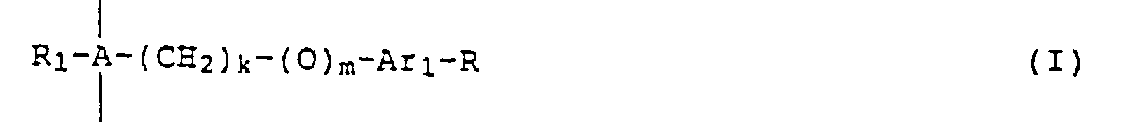
- the liquid crystal oligomer (A) used in the present invention is a side chain type liquid crystal oligomer having recurring units (I) and (II).
- the backbone of the side chain type liquid crystal oligomer is constituted by a polysiloxane.
- Such an oligomer may be of a linear-chain or cyclic structure, but the cyclic structure is preferred because of better chemical stability.
- the length of the spacer, the type of mesogen group and the degree of polymerization of the side chain type liquid crystal oligomers (A) are preferably so selected that the transition temperature from liquid crystal phase to isotropic phase (which may hereinafter be referred to as liquid crystal phase/isotropic phase transition temperature) will become 200°C or below, preferably 170°C or below, more preferably 150°C or below, for facilitating drying with the substrate or orientation treatment, although the upper limit temperature showing the liquid crystal phase is not specifically defined.
- the transition temperature from crystal phase or glass phase to liquid crystal phase of these liquid crystal oligomers is not defined; such transition may be carried out at a temperature lower than room temperature.
- the side chain type liquid crystal oligomer used in the present invention needs to be oriented to have anisotropy of refractive index, and the number of the structural recurring units of the liquid crystal oligomer (A) is an important factor for facilitation of the orienting operation.
- the number of the recurring units is large, the viscosity of the oligomer and its liquid crystal transition temperature elevate, necessitating a high temperature and a long time for effecting desired orientation.
- orientation tends to relax under a room temperature condition.
- the n : n' ratio should fall in a range of 20 : 1 to 1 : 20, preferably 5 : 1 to 1 : 20. The n/n' ratio may be properly adjusted when synthesizing the liquid crystal oligomer as described later.
- the liquid crystal transition temperature and orientation characteristics of the side chain type liquid crystal oligomer (A) are also affected by the spacer connecting the mesogen group to the backbone. Too short a spacer deteriorates the orientation characteristics of mesogen group while too long spacer tends to cause relaxation of orientation. Therefore, as spacer, alkylene group or alkyleneoxy group with a carbon number of 2 to 10 is preferred. C 2 -C 6 alkylene or alkyleneoxy group is especially preferred because of easier orientation. For facilitation of synthesis, alkyleneoxy group is more preferred.
- Typical examples of the preferred groups are -(CH 2 ) 2 -, -(CH 2 ) 3 -, -(CH 2 ) 4 -, -(CH 2 ) 5 -, -(CH 2 ) 6 -, -(CH 2 ) 3 -O-, -(CH 2 ) 4 -O-, -(CH 2 ) 5 -O- and -(CH 2 ) 6 -O-.
- mesogen group used in this invention is preferably one which has large anisotropy of refractive index.
- the structures which can provide such mesogen group include those of the oligomers composed of the recurring units (I) and (II) wherein Ar 1 , Ar 2 and Ar 3 represent independently 1,4-phenylene group, 1,4-cyclohexylene group, pyridine-2,5-diyl group or pyrimidine-2,5-diyl group. More preferably, Ar 1 , Ar 2 and Ar 3 are independently 1,4-phenylene group, pyridine-2,5-diyl group or pyrimidine-2,5-diyl group, most preferably 1,4-phenylene group.
- the group R in the recurring unit (I) contributes to the development of cholesteric phase, so that it is essential that the group R be an optically active group, and in view of stabilization of cholesteric phase, a group having the following structure is preferred: or wherein R 3 represents -H or the following formula: wherein R 4 represents -H or a methyl group, and R 5 represents -H or R 6 (R 6 represents a linear or branched C 1 -C 20 alkyl group or a linear or branched C 1 -C 20 alkoxycarbonyl group, and may have asymmetric carbon when branched).
- the connecting group L' is -CH 2 -CH 2 -, -COO-or -OCO-, more preferably -COO- group.
- the terminal group of the recurring unit (II) is a group for fixing orientation of the liquid crystal oligomer by polymerization.
- the polymerization method of these groups is not specified, but usually photopolymerization or thermal polymerization using a radical polymerization initiator is employed. Photopolymerization is preferred for simplicity of operation and high orientation fixing efficiency. Known photopolymerization initiators can be used.
- those of Nos. 67-72, 79-84, 91-96, 139-144 and 151-156 are preferred. Those of Nos. 79-84 are especially preferred.
- those bonded to the linear or cyclic polysiloxane-based backbone are preferred for high orientation performance. Those bonded to the cyclic polysiloxane backbone are most preferred.
- the optically anisotropic film of the present invention in case it has negative anisotropy of refractive index which is effectual for compensating viewing angle dependence of contrast or display color of TN cell due to refractive anisotropy of the liquid crystal molecules in a wide temperature range, it is necessary to adjust the helical pitch length of the cholesteric phase of the liquid crystal composition to 0.3 ⁇ m or less or to 0.8 ⁇ m or more in order to avoid selective reflection of visible light.
- the twist angle of twisted nematic alignment of the film must be adjusted to stay in a range of 70-300°.
- the helical pitch length of the cholesteric phase is small, it is necessary to reduce the film thickness for adjusting the twist angle of twisted nematic alignment to be in a range of 70-300°, which makes it hard to obtain a desired retardation.
- the pitch length is large, it needs to increase the film thickness for realizing a required twist angle, which poses an economical problem.
- the helical pitch length of the cholesteric phase of the liquid crystal composition can be controlled by adjusting the mesogen group structure of the liquid crystal oligomer (A) or by changing the recurring unit (I)/(II) ratio.
- liquid crystal oligomers (A) For the synthesis of the liquid crystal oligomers (A), the methods disclosed in U.S.P. 4,410,570, U.S.P. 4,358,391 and U.S.P. 5,211,877 can be employed. More specifically, there can be used a method in which said side chain mesogen group is added to the polysiloxane backbone.
- the reacting material having the same structure as the side chain mesogen group of the recurring units (I) and (II) and having ⁇ -alkenyloxy group producing an alkyleneoxy group (spacer) and having unsaturated double bond at the terminal is reacted with polysiloxane in the presence of a platinum catalyst.
- a platinum catalyst it is possible to control the bonding ratio of the two types of mesogen groups, i.e., non-polymerizable mesogen groups and polymerizable mesogen groups, by adjusting the feed rate of the reacting material relative to said mesogen groups.
- the liquid crystal oligomer obtained in the manner described above is preferably one which shows a cholesteric phase.
- Another method of controlling the helical pitch length of the liquid crystal composition comprises mixing in the liquid crystal oligomer (A) other types of liquid crystal oligomer or a low-molecular weight compound.
- the other types of liquid crystal oligomer to be mixed with the oligomer (A) there can be used, in addition to those selected from the liquid crystal oligomers (A), the liquid crystal oligomers (B) having the recurring units (V) and (VI) as main structural units.
- the side chain type liquid crystal oligomer used in the present invention needs to be oriented so that it will have anisotropy of refractive index, and in this case the number of the recurring units of the liquid crystal oligomer (B) becomes a key factor in facilitating the orienting operation.
- the number of the recurring units is large, viscosity of the oligomer and its liquid crystal transition temperature are high, necessitating a high temperature and a long time for effecting desired orientation.
- orientation may be relaxed under a room temperature condition.
- the n''/n''' ratio may be properly selected and can be adjusted when synthesizing the liquid crystal oligomer.
- the liquid crystal transition temperature and orientation characteristics of the side chain type liquid crystal oligomer (B) are also affected by the spacer connecting the mesogen group to the backbone. Too short a spacer deteriorates the orientation characteristics of mesogen group while too long spacer tends to cause relaxation of orientation. Therefore, as spacer, alkylene group or alkyleneoxy group with a carbon number of 2 to 10 is preferred. C 2 -C 6 alkylene or alkyleneoxy group is especially preferred because of easier orientation. For facilitation of synthesis, alkyleneoxy group is more preferred.
- Typical examples of the preferred groups are -(CH 2 ) 2 -, -(CH 2 ) 3 -, -(CH 2 ) 4 -, -(CH 2 ) 5 -, -(CH 2 ) 6 -, -(CH 2 ) 3 -O-, -(CH 2 ) 4 -O-, -(CH 2 ) 5 -O-and -(CH 2 ) 6 -O-.
- mesogen group of the liquid crystal oligomer (B) is preferably one which has large anisotropy of refractiver index.
- the structures which can provide such mesogen group include those of the oligomers composed of the recurring units (V) and (VI) wherein Ar 2 , Ar 3 , Ar 4 and Ar 5 represent independently 1,4-phenylene group, 1,4-cyclohexylene group, pyridine-2,5-diyl group or pyrimidine-2,5-diyl group. Preferably they represent independently 1,4-phenylene group, pyridine-2,5-diyl group or pyrimidine-2,5-diyl group, most preferably 1,4-phenylene group.
- the connecting groups L' and L'' are independently -CH 2 -CH 2 -, -COO- or -OCO-, more preferably -COO- group.
- the group R'' in the recurring unit (V) influences dielectric anisotropy and orientation performance of mesogen group, so that R'' is selected from halogen, cyano group, C 1 -C 10 alkyl group, C 1 -C 10 alkoxy group, C 6 -C 10 aryl group and benzoyloxy group having C 1 -C 10 alkyl group or C 1 -C 10 alkoxy group, preferably cyano group, C 1 -C 10 alkyl group and C 1 -C 10 alkoxy group, more preferably cyano group, for obtaining a liquid crystal oligomer film with high anisotropy of refractive index.
- mesogen groups those of Nos. 157-162, 187-192, 217-222, 337-342 and 367-372 having cyano group are preferred. Those of Nos. 187-192 are especially preferred. Of these mesogen groups, those bonded to the polysiloxane-based backbone are preferred for high orientation performance. Those bonded to the cyclic siloxane backbone are most preferred.
- the terminal group of the recurring unit (VI) is a group for fixing orientation of the liquid crystal oligomer by polymerization.
- the polymerization method of these groups is not specified, but usually photopolymerization or thermal polymerization using a radical polymerization initiator is employed. Photopolymerization is preferred for ease of operation and high orientation fixing efficiency. Known photopolymerization initiators can be used.
- polymerizable mesogen groups used for the linear or cyclic liquid crystal oligomers having the recurring units (VI) those shown in Tables 3 and 4 can be employed.
- those of Nos. 67-72, 79-84, 91-96, 139-144 and 151-156 having methacrylate group are preferred, and those of Nos. 79-84 are especially preferred.
- those bonded to the linear or cyclic polysiloxane-based backbone are preferred as they give good properties to the subject oligomers, and those bonded to the cyclic polysiloxane backbone are especially preferred.
- liquid crystal oligomers (B) For the synthesis of these liquid crystal oligomers (B), there can be employed the same methods as used for the synthesis of liquid crystal oligomers (A) mentioned above.
- the liquid crystal oligomer (B) obtained in the manner described above is preferably one which shows the nematic phase.
- the helical pitch length of the cholesteric phase is controlled by mixing a low-molecular weight compound with the liquid crystal oligomer (A) or a mixture of liquid crystal oligomers (A) and (B)
- the liquid crystal composition is polymerized after orientation, so that compatibility after polymerization becomes an important factor for the successful production of said film.
- the low-molecular weight compound used in this process is preferably one having a polymerizable group. It is also desirable that the polymerizable low-molecular weight compound to be added to the liquid crystal oligomer is of a structure which shows a liquid crystal phase for uniform mixing.
- a is an integer of 1 to 10
- b is an integer of 0 to 10
- R is a linear or branched C 1 -C 10 alkyl or alkoxy group. The group R may be optically active when branched.
- the amount of the low-molecular weight compound added is preferably 0 to 50 wt%, more preferably 0 to 40 wt%, based on the liquid crystal composition. When the compound is added in excess of 50 wt%, film forming properties of the composition and/or orientation stability may be impaired.
- the process for producing an optically anisotropic film according to the present invention comprises the steps of forming a film of a liquid crystal composition, heat treating the formed film so that the helical axis of twisted nematic alignment will become substantially parallel to the direction normal to the film plane, and then polymerizing the polymerizable group of low-molecular weight compound and/or liquid crystal oligomers (A) and/or (B).
- the method of forming a film of a liquid crystal composition is not critical in this invention, but usually a film is formed on a smooth substrate.
- the optically anisotropic film formed on the substrate may be peeled from the substrate and attached to another substrate or it may be used with the substrate attached thereto.
- the substrate used in the present invention is preferably transparent or semitransparent, and the usable substrates include inorganic substrates such as glass, and polymer films.
- Inorganic substrates include transparent or semitransparent glass plates, outer side of glass plate used for liquid crystal cell, and plates of inorganic compounds such as oxides or fluorides of Si, Al, Mg, Zr or the like, and ceramics.
- Polymer films include the films of polycarbonates, polysulfone, polyarylates, polyether sulfone, cellulose diacetate, cellulose triacetate, polystyrene, ethylene-vinyl alcohol copolymer, polyethylene terephthalate, polyethylene naphthalate and the like. Of these polymers, polycarbonates, polyarylates, polysulfone, cellulose triacetate, polyethylene terephthalate and polystyrene are preferred.
- Thickness of the polymer film used as substrate is not specified, but it is preferably 0.8-500 ⁇ m, more preferably 10-300 ⁇ m, even more preferably 40-200 ⁇ m.
- various molding methods such as solvent casting, extrusion molding, press molding, etc., can be employed.
- the liquid crystal composition is oriented so that the helical axis of twisted nematic alignment will become substantially parallel to the direction normal to the film plane.
- a horizontal alignment treatment is applied on the substrate surface.
- the substrate with no liquid crystal oligomer film formed yet thereon is directly rubbed or rubbing is applied after an alignment layer has formed on the substrate.
- the latter method is preferred for stability of alignment.
- Known materials capable of horizontally aligning the liquid crystal molecules such as polyimides, polyamides and polyvinyl alcohol, can be used for forming the alignment layer.
- the alignment layer can be formed by employing a suitable coating method such as roll coating, gravure coating, bar coating, spin coating, spray coating, printing, dipping, etc.
- a suitable coating method such as roll coating, gravure coating, bar coating, spin coating, spray coating, printing, dipping, etc.
- the layer can perform its normal aligning function when its thickness is 0.01 ⁇ m or greater, but the layer workability is deteriorated when the layer is too thick, so that the layer thickness is preferably in a range of 0.01 to 5.0 ⁇ m, more preferably 0.02 to 3.0 ⁇ m.
- the thus formed alignment layer is subjected to after-treatments such as drying and curing according to the type of the layer and then rubbed.
- a known method can be employed for rubbing in this invention. For instance, in case of using a rubbing roller, no specific restrictions are imposed on the material of the roller, amount of penetration of the roller into the layer, moving rate of the roller relative to the substrate, frequency of rubbing, etc., and the optimal conditions can be selected in consideration of the type of the alignment layer, the type of the liquid crystal oligomer and other factors.
- oblique evaporation there can be used, for instance, a method using an oblique deposit of an inorganic material.
- the inorganic material used in this method is preferably one which shows a prismatic or a columnar growth during evaporation.
- examples of such inorganic materials include SiO, SiO 2 , SiOx (1 ⁇ x ⁇ 2), MgO, MgOy (0 ⁇ y ⁇ 1), MgF 2 , Pt, ZnO, MoO 3 , WO 3 , Ta 2 O 5 , SnO 2 , CeO 2 , LiNbO 3 , LiTaO 3 , ZrO 2 , Bi 2 O 3 , TiZrO 4 , HfO 2 and the like.
- SiO, SiO 2 , SiOx (1 ⁇ x ⁇ 2), MgO, MgOy (0 ⁇ y ⁇ 1), MgF 2 , Pt and ZnO are preferred, and SiO, SiO 2 and SiOx (1 ⁇ x ⁇ 2) are most preferred.
- evaporation by resistance heating evaporation by electron beam heating and sputtering.
- evaporation by electron beam heating and sputtering are preferred for evaporating a high-melting point inorganic material.
- the degree of vacuum for evaporation is not specified, but the upper limit pressure is decided in view of uniformity of the evaporation film while the lower limit pressure is decided in view of productivity.
- the degree of vacuum used for evaporation is usually in a range of 1 Torr to 5 x 10 -6 Torr.
- the evaporation rate of the inorganic material is preferably in a range of 0.01 to 10 nm/sec, more preferably 0.1 to 5 nm/sec, because an evaporation rate below the above-defined range leads to a poor productivity while an evaporation rate above said range is detrimental to uniformity of the evaporation film.
- the thickness of the evaporated film of inorganic material good alignment can not be obtained when the film thickness is thin and productivity is lowered when the film thickness is thick, so that the film thickness is usually in a range of 0.01 to 1,000 ⁇ m, preferably 0.05 to 100 ⁇ m, more preferably 0.1 to 5 ⁇ m.
- a film of a liquid crystal composition is formed on the substrate which has undergone said horizontal alignment treatment.
- the film can be formed by coating a liquid crystal composition on the substrate in the state of solution or in the state of isotropic phase. Coating in the state of solution is preferred. Ordinary coating methods such as roll coating, gravure coating, bar coating, spin coating, spray coating, printing, dipping, etc., can be used.
- Thickness of the liquid crystal composition film is preferably 0.1 to 20 ⁇ m, more preferably 0.5 to 10 ⁇ m, even more preferably 1 to 7 ⁇ m.
- the film thickness is less than 0.1 ⁇ m, the film may fail to develop its optical properties to a satisfactory degree.
- a film thickness exceeding 20 ⁇ m is undesirable in economical terms.
- the film thickness also needs to be set in consideration of the twist angle required for an optically anisotropic film and the helical pitch length of the liquid crystal composition used.
- an optically anisotropic film having negative anisotropy of refractive index effective for compensating angle dependence of contrast or display color due to refractive anisotropy of the liquid crystal cell over a wide temperature range it is desirable that the film thickness is more than 3 times, preferably more than 5 times, even more preferably more than 10 times the helical pitch length of cholesteric phase of the liquid crystal composition.
- the film thickness is small, there may undesirably take place leakage of light in the case of placing a sample between orthogonally positioned polarizing plates due to optical rotation of the cholesteric orientation.
- a heat treatment of liquid crystal composition is carried out.
- This heat treatment is preferably conducted in a temperature range defined by (Tg + 30) ⁇ T heat ⁇ (T soft - 30), preferably (Tg + 40) ⁇ T heat ⁇ (T soft - 40) wherein T heat (°C) is heat treatment temperature, Tg (°C) is transition temperature from crystal phase or glass phase to liquid crystal phase of the liquid crystal composition, and T soft (°C) is the temperature which causes deformation of the substrate or the alignment film.
- the heat treatment is preferably carried out in a temperature range of 60-200°C in view of ease of the operation.
- the period of heat treatment is also not critical, but since too short a time can not provide sufficient twisted nematic alignment while too long a time is unfavorable in economical terms, the heat treatment time is preferably 0.2 minutes to 20 hours, more preferably one minute to one hour.
- the above heat treatment allows the liquid crystal composition to have twisted nematic alignment with the helical axis disposed parallel to the direction normal to the film plane.
- the heating and cooling rates in the heat treatment are not specified.
- the liquid crystal composition is polymerized for fixing twisted nematic alignment.
- the polymerization method since it is necessary to carry out polymerization while maintaining said alignment, photopolymerization, radiation polymerization using ⁇ -rays, etc., or thermal polymerization is recommended.
- Known polymerization initiators can be used for photopolymerization and thermal polymerization. Of these polymerization methods, photopolymerization and thermal polymerization are preferred because of simple process, photopolymerization being most preferred for good retention of alignment.
- the intensity of irradiation light applied for photopolymerization may be properly decided depending on the film thickness and the type of the liquid crystal oligomer used, but usually it is recommended to apply light of an intensity of 0.01 to 5.0 J/cm 2 , preferably 0.1 to 3.0 J/cm 2 .
- the applied light intensity is below 0.01 J/cm 2 , the reaction of the polymerizable group may be incomplete.
- Use of light with a higher intensity than 5.0 J/cm 2 poses an economical problem.
- At least one optically anisotropic film of the present invention is disposed between a liquid crystal cell comprising a liquid crystal layer held between a pair of substrates provided with electrodes, said liquid crystal layer including liquid crystal molecules having positive anisotropy of dielectric constant and oriented substantially horizontally with a helical axis aligned vertically to the substrate when no electrical voltage is applied, and at least one polarizing film disposed on either upper or lower outside, or both outsides of said cell.
- Examples of the liquid crystal cell comprising a liquid crystal layer oriented substantially horizontally with a helical axis aligned vertically to the substrate when no electrical voltage is applied, which can be adapted in a liquid crystal display device of the present invention, are a TN type liquid crystal cell with a twist angle of approximately 90°and an STN type liquid crystal cell with a twist angle of 180-300°.
- the twist angle of the liquid crystal cell can be adjusted by the amount of the twisting agent added to the liquid crystal composition or by the alignment treatment of the upper and lower substrates.
- the way of disposition of the polarizing plate and the optically anisotropic film of the present invention is not specified, and they can be appropriately disposed according to the required product properties.
- said optically anisotropic film may be disposed on one side alone of the liquid crystal cell or on both sides thereof as far as the film is positioned between the polarizing plate and the liquid crystal cell.
- At least one optically anisotropic film of the present invention is disposed between a liquid crystal cell comprising a liquid crystal layer held between a pair of substrates provided with electrodes, said liquid crystal layer including liquid crystal molecules having positive anisotropy of dielectric constant and oriented substantially horizontally to the substrate when no electrical voltage is applied, and at least one polarizing film disposed on either upper or lower outside, or both outsides of said cell.
- a liquid crystal cell comprising a liquid crystal layer having positive anisotropy of dielectric constant and oriented substantially horizontally to the substrate when no electrical voltage is applied, which can be adapted in a liquid crystal device of the present invention.
- the way of disposition of the polarizing plate and the optically anisotropic film of the present invention is not specified, and they can be appropriately disposed in accordance with the required product properties.
- the optically anisotropic film may be provided on one side alone of the liquid crystal cell or on both sides thereof as far as the film is positioned between the polarizing plate and the liquid crystal cell.
- At least one optically anisotropic film of the present invention is disposed between a liquid crystal cell comprising a liquid crystal layer held between a pair of substrates provided with electrodes, said liquid crystal layer including liquid crystal molecules having negative anisotropy of dielectric constant and oriented substantially vertically to the substrate when no electrical voltage is applied, and at least one polarizing film disposed on either upper or lower outside, or both outsides of said cell.
- the liquid crystal cell comprising a liquid crystal layer held between a pair of substrates provided with electrodes, having negative anisotropy of dielectric constant and oriented substantially vertically to the substrate when no electrical voltage is applied, which can be adapted in the liquid crystal display device of the present invention, can be produced by placing the liquid crystal composition between a pair of substrates which have been subjected to a vertical alignment treatment.
- the way of disposition of the polarizing film and the optically anisotropic film of the present invention is not specified, and they can be appropriately disposed according to the required product properties.
- said optically anisotropic film may be provided on one side alone of the liquid crystal cell or on both sides thereof as far as the film is positioned betweeen the polarizing plate and the liquid crystal cell.
- phase transition temperature of the liquid crystal oligomers was determined by polarization microscopical observation and measurement by a differential scanning calorimeter (DSC).
- Negative anisotropy of refractive index of the obtained optically anisotropic film was confirmed by zero retardation in the plane vertical to the normal line of the film and increase of retardation with slanting of the film from the horizontal plane.
- Retardation of the film was determined by Sénarmont's method using a polarization microscope with light of 546 nm.
- the twist angle of the obtained optically anisotropic film was determined by applying linearly polarized light to the optically anisotropic film and determining the direction of oscillation of the emitted linearly polarized light (using MCPD-1000 mfd. by Otsuka Denshi KK).
- the phase difference [ ⁇ n ⁇ d ( ⁇ n is apparent anisotropy of refractive index of the film and d is film thickness)] of the optically anisotropic film was determined by analyzing the transmitted light spectrum obtained by using a cell gap measuring device (TFM-120AFT mfd. by Orc Seisakusho Ltd.).
- a polyimide alignment layer was formed on a cleaned glass substrate by spin coating and heat treated at 200°C for 3 hours.
- the formed alignment layer was approximately 0.02 ⁇ m thick. This alignment layer was rubbed by using a rubbing machine.
- the glass transition temperature and the liquid crystal phase/isotropic phase transition temperature of the obtained liquid crystal oligomer were 14°C and 114°C, respectively, and the oligomer showed a cholesteric phase in the temperature range of 14-114°C.
- the selective reflection wavelength of the liquid crystal oligomer alone was determined to be 280 nm. From this wavelength, the helical pitch of the cholesteric phase of said liquid crystal oligomer is given as 0.2 ⁇ m.
- This liquid crystal oligomer was dissolved in toluene to a concentration of 40%, and then Irgacure 907 (produced by Ciba Geigy AG) was mixed in the solution as photopolymerization initiator in an amount of 2.0 wt% based on the liquid crystal oligomer.
- This solution was spin coated on a glass substrate having a polyimide alignment layer.
- the obtained liquid crystal oligomer film was cloudy and polarization microscopical observation thereof showed that the film was not aligned at all.
- This liquid crystal oligomer film was heated at 80°C for 5 minutes and then irradiated with ultraviolet light from a high pressure mercury lamp at a cumulative irradiation dose of 0.2 J/cm 2 .
- Thickness of the thus obtained polymerized liquid crystal oligomer film was 6 ⁇ m, which is 30 times the helical pitch of the cholesteric phase, and no tinting by selective reflection of the visible light was observed.
- This polymerized liquid crystal oligomer film became optically extinct when placed under crossed nicols, and retardation was almost zero. Retardation after a tilt of 50° was 46 nm.
- a polyvinyl alcohol alignment layer was formed on a cleaned glass substrate by spin coating and heat treated at 100°C for one hour.
- the obtained alignment layer was approximately 0.05 ⁇ m thick. This alignment layer was rubbed by using a rubbing machine.
- the obtained liquid crystal oligomer had a glass transition temperature of 20°C and a liquid crystal phase/isotropic phase transition temperature of 97°C and showed the nematic phase at 20-97°C.
- a 5 : 95 (by weight) mixture of this liquid crystal oligomer and the liquid crystal oligomer used in Example 1 was dissolved in toluene to a solid concentration of 30 wt%, and then Irgacure 907 (produced by Ciba Geigy AG) was mixed in the solution as photopolymerization initiator in an amount of 2.0 wt% based on the liquid crystal oligomer.
- This solution was spin coated on a glass substrate having a polyvinyl alcohol alignment layer.
- This liquid crystal oligomer film was gradually cooled from the temperature at which the film assumed the isotropic phase, and after alignment, the film was irradiated with ultraviolet light from a high pressure mercury lamp at a cumulative irradiation dose of 0.2 J/cm 2 .
- the obtained polymerized liquid crystal oligomer film was 3 ⁇ m thick, and no tinting by selective reflection of the visible light was observed.
- This polymerized liquid crystal oligomer film became optically extinct when placed under crossed nicols, and retardation was substantially zero. It showed retardation of 21 nm when tilted 50°.
- a polyvinyl alcohol alignment layer was formed on a cleaned glass substrate by spin coating and heat treated at 100°C for one hour.
- the obtained alignment layer was approximately 0.05 ⁇ m thick. This alignment layer was rubbed by a rubbing machine.
- a 1 : 1 mixture of the vinyl monomer (2) used in Example 1 and the vinyl monomer (3) used in Example 2 was reacted with pentamethylcyclopentasiloxane in the same manner as described in JP-B-63-41400 to obtain a cyclic pentasiloxane liquid crystal oligomer.
- the glass transition temperature and the liquid crystal phase/isotropic phase transition temperature of this liquid crystal oligomer were 19°C and 118°C, respectively, and it showed the smectic phase at 19-118°C.
- a 10 : 90 (by weight) mixture of this liquid crystal oligomer and the liquid crystal oligomer used in Example 1 was dissolved in toluene to a solid concentration of 30 wt%, and then Irgacure 907 (produced by Ciba Geigy AG) was mixed in the solution as photopolymerization initiator in an amount of 2.0 wt% based on the liquid crystal oligomer.
- This solution was spin coated on a glass substrate having a polyvinyl alcohol alignment layer.
- this liquid crystal oligomer film was gradually cooled from the temperature at which the film assumed isotropic phase, and after alignment, the film was irradiated with ultraviolet light from a high pressure mercury lamp at a cumulative irradiation dose of 0.2 J/cm 2 .
- the obtained polymerized liquid crystal oligomer film was 4 ⁇ m thick, and no tinting by selective reflection of the visible light was observed.
- This polymerized liquid crystal oligomer film became optically extinct when placed under crossed nicols, and retardation was substantially zero.
- the film showed retardation of 15 nm when tilted 50°.
- a TN liquid crystal panel with small viewing angle dependence of contrast can be obtained by placing an optically anisotropic film obtained in Examples 1-3 between a TN liquid crystal cell and a polarizing film.
- a polyvinyl alcohol alignment layer was formed on a cleaned glass substrate by spin coating and heat treated at 100°C for one hour. Thickness of the obtained alignment layer was approximately 0.05 ⁇ m. This alignment layer was rubbed by a rubbing machine.
- a 3 97 (by weight) mixture of the cyclic pentasiloxane liquid crystal oligomer (A) obtained in Example 1 and the cyclic pentasiloxane liquid crystal oligomer (B) obtained in Example 2 was dissolved in toluene to a solid concentration of 30 wt%, and then Irgacure 907 (produced by Ciba Geigy AG) was mixed in the solution as photopolymerization initiator in an amount of 2.0 wt% based on the liquid crystal oligomer. This solution was spin coated on a glass substrate having a polyvinyl alcohol alignment layer.
- This liquid crystal oligomer film was heated to the temperature at which the film assumed isotropic phase, and then gradually cooled for alignment. Thereafter, the film was irradiated with ultraviolet light from a high pressure mercury lamp at a cumulative irradiation dose of 0.2 J/cm 2 .
- Thickness of the obtained polymerized liquid crystal oligomer film was 3.0 ⁇ m, its twist angle was 243°, and ⁇ n ⁇ d at room temperature was 0.748 ⁇ m.
- ⁇ n ⁇ d of this optically anisotropic film measured at 55°C was 0.646 ⁇ m, which was 86% of that at room temperature.
- Example 4 The procedure of Example 4 was carried out except that the liquid crystal oligomer (A) : (B) mixing ratio (by weight) was changed to 4 : 96 to produce a liquid crystal oligomer film. Thickness of the obtained polymerized liquid crystal oligomer film was 3.4 ⁇ m, its twist angle was 220° and ⁇ n ⁇ d at room temperature was 0.980 ⁇ m.
- ⁇ n ⁇ d of the obtained optically anisotropic film at 55°C was 0.906 ⁇ m, which was 92% of that at room temperature.
- Example 4 The procedure of Example 4 was followed except the liquid crystal oligomer (A) : (B) ratio (by weight) was changed to 5 : 95 to obtain a liquid crystal oligomer film. Thickness of the obtained polymerized liquid crystal oligomer film was 2.8 ⁇ m, its twist angle was 213° and ⁇ n ⁇ d at room temperature was 0.925 ⁇ m.
- An STN liquid crystal cell having excellent viewing angle characteristics and contrast can be obtained by placing said polymerized liquid crystal oligomer film between an STN liquid crystal cell and a polarizing plate.
- the present invention it is possible to obtain a retardation plate having a wide viewing angle by using an optically anisotropic film having negative anisotropy of refractive index or twisted nematic alignment.
- this retardation plate to TN type or STN type liquid crystal displays, it is possible to markedly improve the display characteristics, especially viewing angle characteristics, of the liquid crystal display devices. Further, in the optically anisotropic film of the present invention, because of similarity to liquid crystal panel in temperature dependence of refractive anisotropy, it is possible to improve the viewing angle characteristics of the liquid crystal cell over a wide temperature range.
Claims (17)
- Film optiquement anisotrope comprenant une composition de cristal liquide ayant un alignement nématique torsadé, caractérisé en ce que l'axe hélicoïdal de l'alignement nématique torsadé est essentiellement parallèle à la direction normale au plan du film, et ladite composition de cristal liquide présente une phase cholestérique et contient au moins un oligomère mésomorphe choisi parmi les oligomères mésomorphes linéaires ou cycliques (A) ayant les motifs répétitifs (I) et (II) ci-après en tant que motifs structuraux, où, quand le nombre des motifs répétitifs (I) et (II) se trouvant dans une molécule de l'oligomère mésomorphe (A) est supposé être respectivement n et n', n et n' représentent chacun indépendamment de l'autre un entier de 1 à 20 et satisfont aux relations 4 ≤ n + n' ≤ 21 et n : n' = 20 : 1 à 1 : 20, et le groupe terminal du motif répétitif (Il) de l'oligomère mésomorphe (A) est polymérisé
 où A est un groupe représenté par la formule (III) ci-après :
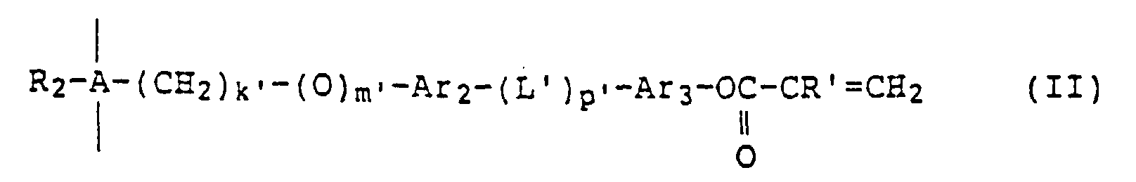 où -Si-O- est une chaíne principale du motif répétitif (I) ou (II) ; R1 et R2 représentent chacun indépendamment de l'autre un atome d'hydrogène, un groupe alkyle ayant de 1 à 6 atomes de carbone ou un groupe phényle, k et k' sont chacun indépendamment de l'autre un entier de 2 à 10 ; m et m' valent chacun indépendamment de l'autre 0 ou 1 ; Ar1, Ar2 et Ar3 représentent chacun indépendamment des autres un groupe 1,4-phénylène, un groupe 1,4-cyclo-hexylène, un groupe pyridine-2,5-diyle ou un groupe pyrimidine-2,5-diyle ; L' est -CH2-O-, -O-CH2-, -COO-, -OCO-,-CH2-CH2-, -CH=N-, -N=CH- ou un groupe divalent représenté par la formule
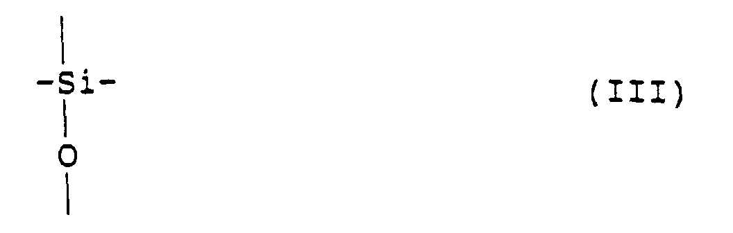 p' représente d'une manière indépendante 0 ou 1 ; R est un groupe optiquement actif ; et R' est un atome d'hydrogène ou un groupe alkyle ayant de 1 à 5 atomes de carbone.
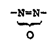
- Film optiquement anisotrope comprenant une composition de cristal liquide ayant un alignement nématique torsadé, caractérisé en ce que l'axe hélicoïdal de l'alignement nématique torsadé est essentiellement parallèle à la direction normale au plan du film ; ladite composition de cristal liquide présente une phase cholestérique et contient au moins un oligomère mésomorphe choisi parmi les oligomères mésomorphes (A) mentionnés dans la revendication 1 et au moins un composé à faible masse moléculaire ayant un groupe polymérisable ; et le groupe terminal du motif répétitif (II) de l'oligomère mésomorphe (A) et/ou le composé à faible masse moléculaire ayant un groupe polymérisable sont polymérisés.
- Film optiquement anisotrope selon la revendication 1 ou 2, dans lequel l'angle de torsadage de l'alignement nématique torsadé de la composition de cristal liquide présentant une phase cholestérique est compris entre 70 et 300°, et ladite composition de cristal liquide présente une phase cholestérique ayant un pas hélicoïdal de 0,2 à 50 µm.
- Film optiquement anisotrope comprenant une composition de cristal liquide ayant un alignement nématique torsadé, caractérisé en ce que l'axe hélicoïdal de l'alignement nématique torsadé est essentiellement parallèle à la direction normale au plan du film, et ladite composition de cristal liquide présente une phase cholestérique et contient au moins un oligomère mésomorphe choisi parmi les oligomères mésomorphes (A) mentionnés dans la revendication 1 et au moins un oligomère mésomorphe choisi parmi les oligomères mésomorphes (B) autres que (A), lesdits oligomères mésomorphes (B) étant choisis parmi les oligomères mésomorphes linéaires ou cycliques ayant les motifs répétitifs (V) et (VI) ci-après en tant que motifs structuraux, où, quand le nombre des motifs répétitifs (V) et (VI) se trouvant dans une molécule de l'oligomère mésomorphe (B) est supposé être respectivement n" et n"', n" et n"' représentent chacun indépendamment de l'autre un entier de 0 à 20 et sont définis par la relation 4 ≤ n" + n‴ ≤ 21, et le groupe terminal du motif répétitif (II) de l'oligomère mésomorphe (A) et/ou le groupe terminal du motif répétitif (VI) de l'oligomère mésomorphe (B) sont polymérisés :
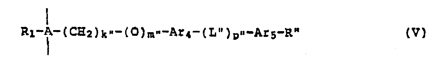 où A, R1, R2, k', m', p', L', Ar2, Ar3 et R' sont tels que définis ci-dessus ; k" est un entier de 2 à 10 ; m" vaut 0 ou 1 ; Ar4 et Ar5 représentent chacun indépendamment de l'autre un groupe 1,4-phénylène, un groupe 1,4-cyclo-hexylène, un groupe pyridine-2,5-diyle ou un groupe pyrimidine-2,5-diyle ; L" est -CH2-O-, -O-CH2-, -COO-, -OCO-, -CH2-CH2-, -CH=N-,-N=CH- ou un groupe divalent représenté par la formule
 p" vaut 0 ou 1 ; et R" est un atome d'halogène, un groupe cyano, un groupe alkyle en C1-C10, un groupe alcoxyle en C1-C10, un groupe aryle en C6-C10 ou un groupe benzoyloxy ayant un groupe alkyle en C1-C10 ou un groupe alcoxyle en C1-C10.
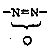
- Film optiquement anisotrope comprenant une composition de cristal liquide ayant un alignement nématique torsadé, caractérisé en ce que l'axe hélicoïdal de l'alignement nématique torsadé est essentiellement parallèle à la direction normale au plan du film ; ladite composition de cristal liquide présente une phase cholestérique et contient au moins un oligomère mésomorphe choisi parmi les oligomères mésomorphes (A) mentionnés dans la revendication 1, au moins un oligomère mésomorphe choisi parmi les oligomères mésomorphes (B) mentionnés dans la revendication 4, et au moins un composé à faible masse moléculaire ayant un groupe polymérisable ; et le groupe terminal du motif répétitif (II) de l'oligomère mésomorphe (A) et/ou le groupe terminal du motif répétitif (VI) de l'oligomère mésomorphe (B) et/ou le composé à faible masse moléculaire ayant un groupe polymérisable sont polymérisés.
- Film optiquement anisotrope selon la revendication 4 ou 5, dans lequel l'angle de torsadage de l'alignement nématique torsadé de la composition de cristal liquide présentant une phase cholestérique est compris entre 70 et 300°, et ladite composition de cristal liquide présente une phase cholestérique ayant un pas hélicoïdal de 0,2 à 50 µm.
- Film optiquement anisotrope selon l'une quelconque des revendications 1 à 6, dans lequel la composition de cristal liquide présentant une phase cholestérique est définie par le fait que, quand l'épaisseur du film optiquement anisotrope est représentée par d (µm) et le pas hélicoïdal de la phase cholestérique est représenté par P (µm), alors d ≥ 3 x P et P ≤ 0,3 µm ou P ≥ 0,8 µm.
- Film optiquement anisotrope selon l'une quelconque des revendications 1 à 7, comprenant un oligomère mésomorphe dans lequel R est représenté par la formule (VII) ou (VIII) ci-après :où R3 représente -H ou la formule (IX) ci-après :

 où R4 représente -H ou un groupe méthyle, et R5 représente -H ou R6, où R6 est un groupe alkyle en C1-C20 à chaíne droite ou ramifiée ou un groupe alcoxycarbonyle en C1-C20 à chaíne droite ou ramifiée et, quand il est ramifié, il peut comporter un atome de carbone asymétrique.
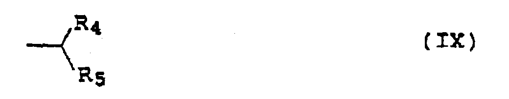
- Procédé de production d'un film optiquement anisotrope, qui consiste à former un film d'une composition de cristal liquide tel que ressortant de l'une quelconque des revendications 1 à 8, à soumettre le film à un traitement thermique de façon que l'axe hélicoïdal de l'alignement nématique torsadé devienne essentiellement parallèle à la direction normale au plan du film, puis à polymériser le groupe polymérisable du composé à faible masse moléculaire et/ou le groupe polymérisable de l'oligomère mésomorphe (A) et/ou le groupe polymérisable de l'oligomère mésomorphe (B).
- Stratifié d'un film optiquement anisotrope selon l'une quelconque des revendications 1 à 8 et d'un substrat transparent ou semi-transparent ayant sur sa surface une couche d'alignement.
- Stratifié selon la revendication 10, dans lequel le substrat est une plaque de verre ou un film polymère.
- Stratifié selon la revendication 10, dans lequel l'indice de réfraction apparent dudit stratifié satisfait à la formule (1) ci-après :
- Dispositif d'affichage à cristaux liquides comprenant une cellule à cristaux liquides comprenant une couche de cristaux liquides maintenue entre deux substrats pourvus d'électrodes, ladite couche de cristaux liquides ayant une anisotropie diélectrique positive et étant orientée d'une manière essentiellement horizontale, avec un axe hélicoïdal aligné verticalement par rapport au substrat en l'absence de tension électrique appliquée, au moins un film polarisant étant disposé sur la face extérieure supérieure ou inférieure, ou sur les deux faces extérieures de ladite cellule à cristaux liquides, et un film optiquement anisotrope selon l'une quelconque des revendications 1 à 8 ou un stratifié constitué d'un film optiquement anisotrope et d'un substrat selon l'une quelconque des revendications 10 à 12, qui est disposé entre ladite cellule à cristaux liquides et ledit film polarisant.
- Dispositif d'affichage à cristaux liquides comprenant une cellule à cristaux liquides comprenant une couche de cristaux liquides maintenue entre deux substrats pourvus d'électrodes, ladite couche de cristaux liquides ayant une anisotropie diélectrique positive et étant orientée d'une manière essentiellement horizontale par rapport aux substrats en l'absence de tension électrique appliquée, au moins un film polarisant étant disposé sur la face extérieure supérieure ou inférieure, ou sur les deux faces extérieures de ladite cellule à cristaux liquides, et un film optiquement anisotrope selon les revendications 7 ou 8, ou un stratifié selon l'une quelconque des revendications 10 à 12, qui est disposé entre ladite cellule à cristaux liquides et ledit film polarisant.
- Dispositif d'affichage à cristaux liquides comprenant une cellule à cristaux liquides comprenant une couche de cristaux liquides maintenue entre deux substrats pourvus d'électrodes, ladite couche de cristaux liquides ayant une anisotropie diélectrique négative et étant orientée d'une manière essentiellement verticale par rapport au substrat en l'absence de tension électrique appliquée, un film polarisant disposé sur la face extérieure de ladite cellule à cristaux liquides, et un film optiquement anisotrope selon les revendications 7 ou 8 ou un stratifié selon l'une quelconque des revendications 10 à 12, qui est disposé entre ladite cellule à cristaux liquides et ledit film polarisant.
- Dispositif d'affichage à cristaux liquides selon la revendication 13, dans lequel la cellule à cristaux liquides est une cellule TN à orientation torsadée, ledit film optiquement anisotrope est au moins un film choisi parmi ceux de l'une quelconque des revendications 1 à 8, et ledit stratifié est au moins un stratifié choisi parmi ceux des revendications 10 à 12.
- Dispositif d'affichage à cristaux liquides selon la revendication 13, dans lequel la cellule à cristaux liquides est une cellule STN à orientation torsadée, ledit film optiquement anisotrope est au moins un film choisi parmi ceux des revendications 3, 6 et 8, et ledit stratifié est au moins un stratifié choisi parmi ceux des revendications 10 à 12.
Applications Claiming Priority (12)
| Application Number | Priority Date | Filing Date | Title |
|---|---|---|---|
| JP22964094 | 1994-09-26 | ||
| JP22963994 | 1994-09-26 | ||
| JP22963994 | 1994-09-26 | ||
| JP229640/94 | 1994-09-26 | ||
| JP22964094 | 1994-09-26 | ||
| JP229639/94 | 1994-09-26 | ||
| JP648795 | 1995-01-19 | ||
| JP00648695A JP3934690B2 (ja) | 1994-09-26 | 1995-01-19 | 光学異方体フィルムとその製造方法および液晶表示装置 |
| JP648695 | 1995-01-19 | ||
| JP6486/95 | 1995-01-19 | ||
| JP6487/95 | 1995-01-19 | ||
| JP00648795A JP3934691B2 (ja) | 1994-09-26 | 1995-01-19 | 光学異方体フィルムとその製造方法および液晶表示装置 |
Publications (3)
| Publication Number | Publication Date |
|---|---|
| EP0704514A2 EP0704514A2 (fr) | 1996-04-03 |
| EP0704514A3 EP0704514A3 (fr) | 1996-05-01 |
| EP0704514B1 true EP0704514B1 (fr) | 2000-01-26 |
Family
ID=27454498
Family Applications (1)
| Application Number | Title | Priority Date | Filing Date |
|---|---|---|---|
| EP95115091A Expired - Lifetime EP0704514B1 (fr) | 1994-09-26 | 1995-09-25 | Film optiquement anisotrope |
Country Status (4)
| Country | Link |
|---|---|
| US (1) | US5730899A (fr) |
| EP (1) | EP0704514B1 (fr) |
| KR (1) | KR100348674B1 (fr) |
| DE (1) | DE69514745T2 (fr) |
Families Citing this family (21)
| Publication number | Priority date | Publication date | Assignee | Title |
|---|---|---|---|---|
| GB2314331B (en) * | 1995-04-07 | 1999-05-26 | Secr Defence | Polysiloxanes |
| GB9507316D0 (en) * | 1995-04-07 | 1995-05-31 | Secr Defence | Polysiloxanes |
| US6697129B1 (en) * | 1996-02-14 | 2004-02-24 | Semiconductor Energy Laboratory Co., Ltd. | Guest-host mode liquid crystal display device of lateral electric field driving type |
| US6008873A (en) * | 1997-08-27 | 1999-12-28 | Motorola, Inc. | Isotropic, non-birefringent polynorbornene alignment layer for a liquid crystal display |
| JP3824772B2 (ja) * | 1998-03-24 | 2006-09-20 | 新日本石油株式会社 | 液晶表示装置 |
| JP2000044797A (ja) * | 1998-04-06 | 2000-02-15 | Kuraray Co Ltd | 液晶ポリマ―フィルムと積層体及びそれらの製造方法並びに多層実装回路基板 |
| GB9828690D0 (en) * | 1998-12-24 | 1999-02-17 | Rolic Ag | Liquid crystal display with improved viewing angle |
| JP2003207644A (ja) * | 2001-11-09 | 2003-07-25 | Dainippon Printing Co Ltd | 光学素子の製造方法 |
| JP2003207642A (ja) * | 2001-11-09 | 2003-07-25 | Dainippon Printing Co Ltd | 光学素子 |
| KR100577792B1 (ko) * | 2001-12-22 | 2006-05-10 | 비오이 하이디스 테크놀로지 주식회사 | 러빙포의 재정렬 기능이 부가된 액정표시장치의 러빙머신및 이를 이용한 러빙방법 |
| US7270855B2 (en) * | 2002-01-23 | 2007-09-18 | Nitto Denko Corporation | Optical film, method for manufacturing the same, and phase difference film and polarizing plate using the same |
| DE10203938A1 (de) * | 2002-02-01 | 2003-08-14 | Basf Ag | Lagerstabile wässrige Miniemulsionen von cholesterischen Gemischen |
| JP4175826B2 (ja) * | 2002-04-16 | 2008-11-05 | シャープ株式会社 | 液晶表示装置 |
| JP3816467B2 (ja) * | 2002-07-10 | 2006-08-30 | エルジー フィリップス エルシーディー カンパニー リミテッド | 液晶表示装置 |
| JP3727638B2 (ja) * | 2003-06-16 | 2005-12-14 | 日東電工株式会社 | 積層光学フィルム、楕円偏光板および画像表示装置 |
| JP3968068B2 (ja) * | 2003-09-30 | 2007-08-29 | 株式会社クラレ | 液晶ポリマーフィルムの製造方法 |
| TWI322290B (en) | 2004-02-13 | 2010-03-21 | Toshiba Matsushita Display Tec | Liquid crystal display |
| CN100446079C (zh) * | 2004-12-15 | 2008-12-24 | 日本电气株式会社 | 液晶显示装置、其驱动方法及其驱动电路 |
| JP4355676B2 (ja) * | 2005-03-31 | 2009-11-04 | 大日本印刷株式会社 | 異方性光学素子の製造方法 |
| KR101717419B1 (ko) * | 2013-09-30 | 2017-03-17 | 주식회사 엘지화학 | 광학 필름 |
| EP3500650B8 (fr) * | 2016-08-17 | 2020-08-12 | Shenzhen Guohua Optoelectronics Tech. Co. Ltd. | Revêtement ou film polymère sensible aux stimuli, dispositifs sensibles et procédé de préparation associé |
Family Cites Families (27)
| Publication number | Priority date | Publication date | Assignee | Title |
|---|---|---|---|---|
| DE2944591A1 (de) | 1979-11-05 | 1981-05-14 | Wacker-Chemie GmbH, 8000 München | Fluessigkristalline phasen aufweisende zusammensetzungen |
| DE3110048A1 (de) | 1981-03-16 | 1982-09-30 | Consortium für elektrochemische Industrie GmbH, 8000 München | "fluessigkristalline phasen aufweisende zusammensetzungen auf basis cyclischer organopolysiloxane, ihre herstellung und deren verwendung" |
| JPS6347759A (ja) * | 1986-08-15 | 1988-02-29 | Fuji Photo Film Co Ltd | 銀塩拡散転写法受像要素 |
| JP2537608B2 (ja) * | 1986-12-15 | 1996-09-25 | セイコーエプソン株式会社 | 液晶表示装置 |
| JPH01222220A (ja) | 1988-03-01 | 1989-09-05 | Matsushita Electric Ind Co Ltd | 光学補償用有機フィルムとその製造方法 |
| DE3830592A1 (de) * | 1988-09-08 | 1990-04-12 | Consortium Elektrochem Ind | (meth)acryloxygruppen enthaltende fluessigkristalline polyorganosiloxane |
| JP2592694B2 (ja) * | 1989-01-26 | 1997-03-19 | 日本石油株式会社 | 液晶表示素子用補償板 |
| NL8901167A (nl) * | 1989-05-10 | 1990-12-03 | Philips Nv | Methode voor de vervaardiging van een polarisatiefilter, een aldus verkregen polarisatiefilter en een display dat voorzien is van het polarisatiefilter. |
| EP0423881B1 (fr) | 1989-10-18 | 1994-02-09 | Koninklijke Philips Electronics N.V. | Dispositif de reproduction à cristaux liquides |
| JP2646281B2 (ja) * | 1990-04-09 | 1997-08-27 | 株式会社リコー | 液晶性高分子薄膜付基板 |
| JP3034899B2 (ja) * | 1990-04-09 | 2000-04-17 | 日本電信電話株式会社 | エンコーダ |
| US5250214A (en) * | 1990-04-09 | 1993-10-05 | Ricoh Company, Ltd. | Liquid crystal color display device provided with a color filter film and an optical phase plate comprising liquid crystal polymer |
| JP2687035B2 (ja) * | 1990-04-13 | 1997-12-08 | 日本石油株式会社 | 液晶表示素子用補償板の製造法 |
| JPH0422917A (ja) * | 1990-05-18 | 1992-01-27 | Nippon Oil Co Ltd | 旋光性光学素子 |
| JP2711585B2 (ja) * | 1990-06-26 | 1998-02-10 | 日本石油株式会社 | アクティブマトリックス液晶表示素子用補償板 |
| US5210530A (en) * | 1991-01-04 | 1993-05-11 | Codex Corporation | Network management interface with internal dsd |
| WO1992014180A1 (fr) * | 1991-02-04 | 1992-08-20 | Seiko Epson Corporation | Matiere optique anisotrope, sa fabrication, dispositif a cristaux liquides dote de ladite matiere et sa production |
| JPH04346312A (ja) | 1991-05-24 | 1992-12-02 | Toshiba Corp | 液晶表示素子 |
| JPH055863A (ja) * | 1991-06-28 | 1993-01-14 | Toshiba Corp | 液晶表示素子 |
| JPH0534675A (ja) * | 1991-07-30 | 1993-02-12 | Toshiba Corp | 液晶表示素子 |
| JPH0534657A (ja) * | 1991-07-30 | 1993-02-12 | Toshiba Corp | 液晶表示素子 |
| JPH0534671A (ja) * | 1991-07-30 | 1993-02-12 | Toshiba Corp | 液晶表示素子 |
| JPH0553133A (ja) * | 1991-08-29 | 1993-03-05 | Toshiba Corp | 液晶表示素子 |
| JP2853068B2 (ja) | 1991-09-03 | 1999-02-03 | 日本石油株式会社 | 液晶表示素子用視角補償板の製造方法 |
| TW289095B (fr) * | 1993-01-11 | 1996-10-21 | ||
| JPH06341400A (ja) * | 1993-02-12 | 1994-12-13 | Masatoshi Takahashi | 水中圧力を空気圧力に変換装置 |
| CA2119484A1 (fr) * | 1993-03-25 | 1994-09-26 | Toshihiro Ohnishi | Materiau optiquement anisotrope, sa methode de fabrication et plaque de retardement et afficheur a cristaux liquides utilisant ce materiau |
-
1995
- 1995-09-25 DE DE69514745T patent/DE69514745T2/de not_active Expired - Lifetime
- 1995-09-25 EP EP95115091A patent/EP0704514B1/fr not_active Expired - Lifetime
- 1995-09-25 KR KR1019950032255A patent/KR100348674B1/ko not_active IP Right Cessation
- 1995-09-26 US US08/533,856 patent/US5730899A/en not_active Expired - Lifetime
Also Published As
| Publication number | Publication date |
|---|---|
| EP0704514A2 (fr) | 1996-04-03 |
| DE69514745D1 (de) | 2000-03-02 |
| EP0704514A3 (fr) | 1996-05-01 |
| KR960011514A (ko) | 1996-04-20 |
| DE69514745T2 (de) | 2000-09-07 |
| KR100348674B1 (ko) | 2002-11-07 |
| US5730899A (en) | 1998-03-24 |
Similar Documents
| Publication | Publication Date | Title |
|---|---|---|
| EP0704514B1 (fr) | Film optiquement anisotrope | |
| EP0617111B1 (fr) | Matériau optiquement anisotrope, procédé de fabrication, plaque de retardement et affichage à cristaux liquides l'utilisant | |
| KR101012892B1 (ko) | 액정 디스플레이 | |
| KR100781978B1 (ko) | 박막 보상기 | |
| JP3783787B2 (ja) | 重合性液晶組成物及び光学異方体の製造方法 | |
| US5601884A (en) | Retardation film and production thereof | |
| JP3579914B2 (ja) | 光学異方性を有する基板 | |
| JP3432572B2 (ja) | 液晶オリゴマー重合物フィルム、その製造方法、並びに液晶オリゴマー重合物フィルムを用いた位相差板および液晶表示装置 | |
| JP3771619B2 (ja) | 液晶表示素子 | |
| AU719031B2 (en) | Temperature matched retardation layer | |
| JP3617653B2 (ja) | 光学異方性を有する基板の製造方法 | |
| JPH09288210A (ja) | 光学異方体フィルムとその製造方法および液晶表示装置 | |
| JP3934690B2 (ja) | 光学異方体フィルムとその製造方法および液晶表示装置 | |
| JPH09325212A (ja) | 光学異方体フィルムおよび液晶表示装置 | |
| JP3404433B2 (ja) | 液晶オリゴマー重合体組成物フィルムとその製造方法および複合位相差板と液晶表示装置 | |
| EP1081534A1 (fr) | Afficheur a cristaux liquides | |
| JP3432584B2 (ja) | 光学異方体フィルムとその製造方法および位相差板と液晶表示装置 | |
| JP3934691B2 (ja) | 光学異方体フィルムとその製造方法および液晶表示装置 | |
| JP3310403B2 (ja) | 配向液晶重合体フィルムとその製造方法、位相差板および液晶表示装置 | |
| JPH0821999A (ja) | 液晶表示装置 | |
| JP3452649B2 (ja) | 光学異方体フィルムとその製造方法および位相差板と液晶表示装置 | |
| JP2869453B2 (ja) | 液晶表示素子 | |
| JP2002174730A (ja) | 光学補償フィルム及び液晶表示素子 | |
| JPH04118629A (ja) | 表示素子 | |
| JPH07294903A (ja) | 液晶表示装置 |
Legal Events
| Date | Code | Title | Description |
|---|---|---|---|
| PUAI | Public reference made under article 153(3) epc to a published international application that has entered the european phase |
Free format text: ORIGINAL CODE: 0009012 |
|
| PUAL | Search report despatched |
Free format text: ORIGINAL CODE: 0009013 |
|
| AK | Designated contracting states |
Kind code of ref document: A2 Designated state(s): DE FR GB NL |
|
| AK | Designated contracting states |
Kind code of ref document: A3 Designated state(s): DE FR GB NL |
|
| 17P | Request for examination filed |
Effective date: 19961002 |
|
| 17Q | First examination report despatched |
Effective date: 19980213 |
|
| GRAG | Despatch of communication of intention to grant |
Free format text: ORIGINAL CODE: EPIDOS AGRA |
|
| GRAG | Despatch of communication of intention to grant |
Free format text: ORIGINAL CODE: EPIDOS AGRA |
|
| GRAH | Despatch of communication of intention to grant a patent |
Free format text: ORIGINAL CODE: EPIDOS IGRA |
|
| GRAH | Despatch of communication of intention to grant a patent |
Free format text: ORIGINAL CODE: EPIDOS IGRA |
|
| GRAA | (expected) grant |
Free format text: ORIGINAL CODE: 0009210 |
|
| AK | Designated contracting states |
Kind code of ref document: B1 Designated state(s): DE FR GB NL |
|
| REF | Corresponds to: |
Ref document number: 69514745 Country of ref document: DE Date of ref document: 20000302 |
|
| ET | Fr: translation filed | ||
| PLBE | No opposition filed within time limit |
Free format text: ORIGINAL CODE: 0009261 |
|
| STAA | Information on the status of an ep patent application or granted ep patent |
Free format text: STATUS: NO OPPOSITION FILED WITHIN TIME LIMIT |
|
| 26N | No opposition filed | ||
| REG | Reference to a national code |
Ref country code: GB Ref legal event code: IF02 |
|
| REG | Reference to a national code |
Ref country code: GB Ref legal event code: 732E |
|
| REG | Reference to a national code |
Ref country code: FR Ref legal event code: TQ |
|
| PGFP | Annual fee paid to national office [announced via postgrant information from national office to epo] |
Ref country code: DE Payment date: 20100922 Year of fee payment: 16 |
|
| PGFP | Annual fee paid to national office [announced via postgrant information from national office to epo] |
Ref country code: GB Payment date: 20110921 Year of fee payment: 17 Ref country code: FR Payment date: 20110922 Year of fee payment: 17 |
|
| PGFP | Annual fee paid to national office [announced via postgrant information from national office to epo] |
Ref country code: NL Payment date: 20110922 Year of fee payment: 17 |
|
| REG | Reference to a national code |
Ref country code: NL Ref legal event code: V1 Effective date: 20130401 |
|
| GBPC | Gb: european patent ceased through non-payment of renewal fee |
Effective date: 20120925 |
|
| REG | Reference to a national code |
Ref country code: FR Ref legal event code: ST Effective date: 20130531 |
|
| REG | Reference to a national code |
Ref country code: DE Ref legal event code: R119 Ref document number: 69514745 Country of ref document: DE Effective date: 20130403 |
|
| PG25 | Lapsed in a contracting state [announced via postgrant information from national office to epo] |
Ref country code: DE Free format text: LAPSE BECAUSE OF NON-PAYMENT OF DUE FEES Effective date: 20130403 Ref country code: GB Free format text: LAPSE BECAUSE OF NON-PAYMENT OF DUE FEES Effective date: 20120925 |
|
| PG25 | Lapsed in a contracting state [announced via postgrant information from national office to epo] |
Ref country code: FR Free format text: LAPSE BECAUSE OF NON-PAYMENT OF DUE FEES Effective date: 20121001 Ref country code: NL Free format text: LAPSE BECAUSE OF NON-PAYMENT OF DUE FEES Effective date: 20130401 |