EP0700514B1 - Vorrichtung und verfahren fuer homogene multianalyt-immuno-assays - Google Patents
Vorrichtung und verfahren fuer homogene multianalyt-immuno-assays Download PDFInfo
- Publication number
- EP0700514B1 EP0700514B1 EP94923161A EP94923161A EP0700514B1 EP 0700514 B1 EP0700514 B1 EP 0700514B1 EP 94923161 A EP94923161 A EP 94923161A EP 94923161 A EP94923161 A EP 94923161A EP 0700514 B1 EP0700514 B1 EP 0700514B1
- Authority
- EP
- European Patent Office
- Prior art keywords
- waveguide
- molecules
- light
- analyte
- capture molecules
- Prior art date
- Legal status (The legal status is an assumption and is not a legal conclusion. Google has not performed a legal analysis and makes no representation as to the accuracy of the status listed.)
- Expired - Lifetime
Links
- 238000000034 method Methods 0.000 title claims abstract description 60
- 239000012491 analyte Substances 0.000 claims abstract description 55
- 238000010168 coupling process Methods 0.000 claims abstract description 45
- 239000011248 coating agent Substances 0.000 claims abstract description 43
- 238000000576 coating method Methods 0.000 claims abstract description 43
- 238000005859 coupling reaction Methods 0.000 claims abstract description 42
- 230000008878 coupling Effects 0.000 claims abstract description 38
- 239000004971 Cross linker Substances 0.000 claims abstract description 26
- 125000003396 thiol group Chemical group [H]S* 0.000 claims abstract description 8
- 230000001678 irradiating effect Effects 0.000 claims abstract 9
- 239000000700 radioactive tracer Substances 0.000 claims description 65
- 230000003287 optical effect Effects 0.000 claims description 45
- 238000001514 detection method Methods 0.000 claims description 42
- 239000000758 substrate Substances 0.000 claims description 39
- 230000027455 binding Effects 0.000 claims description 36
- VYPSYNLAJGMNEJ-UHFFFAOYSA-N Silicium dioxide Chemical compound O=[Si]=O VYPSYNLAJGMNEJ-UHFFFAOYSA-N 0.000 claims description 33
- 239000000523 sample Substances 0.000 claims description 28
- 229920001223 polyethylene glycol Polymers 0.000 claims description 26
- 239000003431 cross linking reagent Substances 0.000 claims description 18
- 102000004169 proteins and genes Human genes 0.000 claims description 18
- 108090000623 proteins and genes Proteins 0.000 claims description 18
- 239000002202 Polyethylene glycol Substances 0.000 claims description 16
- -1 aryl azides Chemical class 0.000 claims description 15
- 229920003171 Poly (ethylene oxide) Polymers 0.000 claims description 14
- 238000003018 immunoassay Methods 0.000 claims description 14
- 239000000377 silicon dioxide Substances 0.000 claims description 14
- 239000000463 material Substances 0.000 claims description 13
- 239000004033 plastic Substances 0.000 claims description 13
- 229920003023 plastic Polymers 0.000 claims description 13
- 238000012360 testing method Methods 0.000 claims description 13
- 238000005406 washing Methods 0.000 claims description 12
- 238000003384 imaging method Methods 0.000 claims description 10
- 239000012965 benzophenone Substances 0.000 claims description 7
- 229920001400 block copolymer Polymers 0.000 claims description 7
- 239000000872 buffer Substances 0.000 claims description 6
- 239000012488 sample solution Substances 0.000 claims description 6
- 238000004519 manufacturing process Methods 0.000 claims description 5
- 150000008366 benzophenones Chemical class 0.000 claims description 4
- 239000003153 chemical reaction reagent Substances 0.000 claims description 4
- 239000007787 solid Substances 0.000 claims description 3
- 230000000638 stimulation Effects 0.000 claims description 3
- 229920001477 hydrophilic polymer Polymers 0.000 claims description 2
- 125000001165 hydrophobic group Chemical group 0.000 claims description 2
- 229920001427 mPEG Polymers 0.000 claims description 2
- 229920001451 polypropylene glycol Polymers 0.000 claims description 2
- 125000003808 silyl group Chemical group [H][Si]([H])([H])[*] 0.000 claims description 2
- 238000007493 shaping process Methods 0.000 claims 2
- 239000012736 aqueous medium Substances 0.000 claims 1
- 229920001577 copolymer Polymers 0.000 claims 1
- JXVXIMINGDDNPF-UHFFFAOYSA-N diphenylmethanone;pyrrole-2,5-dione Chemical group O=C1NC(=O)C=C1.C=1C=CC=CC=1C(=O)C1=CC=CC=C1 JXVXIMINGDDNPF-UHFFFAOYSA-N 0.000 claims 1
- 229920001600 hydrophobic polymer Polymers 0.000 claims 1
- 230000003252 repetitive effect Effects 0.000 claims 1
- PZJJKWKADRNWSW-UHFFFAOYSA-N trimethoxysilicon Chemical compound CO[Si](OC)OC PZJJKWKADRNWSW-UHFFFAOYSA-N 0.000 claims 1
- 230000009871 nonspecific binding Effects 0.000 abstract description 38
- 238000003556 assay Methods 0.000 abstract description 31
- 230000008569 process Effects 0.000 abstract description 11
- 239000012634 fragment Substances 0.000 description 48
- 239000000243 solution Substances 0.000 description 34
- 230000005284 excitation Effects 0.000 description 20
- 239000000427 antigen Substances 0.000 description 18
- 102000036639 antigens Human genes 0.000 description 18
- 108091007433 antigens Proteins 0.000 description 18
- 230000035945 sensitivity Effects 0.000 description 15
- 239000004793 Polystyrene Substances 0.000 description 14
- 229920002223 polystyrene Polymers 0.000 description 14
- 235000018102 proteins Nutrition 0.000 description 14
- 241000894007 species Species 0.000 description 13
- 230000009870 specific binding Effects 0.000 description 13
- 150000001875 compounds Chemical class 0.000 description 12
- LOKCTEFSRHRXRJ-UHFFFAOYSA-I dipotassium trisodium dihydrogen phosphate hydrogen phosphate dichloride Chemical compound P(=O)(O)(O)[O-].[K+].P(=O)(O)([O-])[O-].[Na+].[Na+].[Cl-].[K+].[Cl-].[Na+] LOKCTEFSRHRXRJ-UHFFFAOYSA-I 0.000 description 12
- 238000002474 experimental method Methods 0.000 description 12
- 239000002953 phosphate buffered saline Substances 0.000 description 12
- 229960002685 biotin Drugs 0.000 description 11
- 239000011616 biotin Substances 0.000 description 11
- 239000000017 hydrogel Substances 0.000 description 11
- WYTZZXDRDKSJID-UHFFFAOYSA-N (3-aminopropyl)triethoxysilane Chemical compound CCO[Si](OCC)(OCC)CCCN WYTZZXDRDKSJID-UHFFFAOYSA-N 0.000 description 10
- 108090001008 Avidin Proteins 0.000 description 10
- 239000000975 dye Substances 0.000 description 10
- 238000006243 chemical reaction Methods 0.000 description 9
- 230000001965 increasing effect Effects 0.000 description 9
- JQWHASGSAFIOCM-UHFFFAOYSA-M sodium periodate Chemical compound [Na+].[O-]I(=O)(=O)=O JQWHASGSAFIOCM-UHFFFAOYSA-M 0.000 description 9
- YBJHBAHKTGYVGT-ZKWXMUAHSA-N (+)-Biotin Chemical compound N1C(=O)N[C@@H]2[C@H](CCCCC(=O)O)SC[C@@H]21 YBJHBAHKTGYVGT-ZKWXMUAHSA-N 0.000 description 8
- 102000015636 Oligopeptides Human genes 0.000 description 8
- 108010038807 Oligopeptides Proteins 0.000 description 8
- 238000005259 measurement Methods 0.000 description 8
- 230000035515 penetration Effects 0.000 description 8
- 229920000642 polymer Polymers 0.000 description 8
- 239000011521 glass Substances 0.000 description 7
- 239000000203 mixture Substances 0.000 description 7
- 229920001983 poloxamer Polymers 0.000 description 7
- RTZKZFJDLAIYFH-UHFFFAOYSA-N Diethyl ether Chemical compound CCOCC RTZKZFJDLAIYFH-UHFFFAOYSA-N 0.000 description 6
- ZMXDDKWLCZADIW-UHFFFAOYSA-N N,N-Dimethylformamide Chemical compound CN(C)C=O ZMXDDKWLCZADIW-UHFFFAOYSA-N 0.000 description 6
- 210000004027 cell Anatomy 0.000 description 6
- GNBHRKFJIUUOQI-UHFFFAOYSA-N fluorescein Chemical compound O1C(=O)C2=CC=CC=C2C21C1=CC=C(O)C=C1OC1=CC(O)=CC=C21 GNBHRKFJIUUOQI-UHFFFAOYSA-N 0.000 description 6
- 230000000644 propagated effect Effects 0.000 description 6
- 239000007974 sodium acetate buffer Substances 0.000 description 6
- 239000000126 substance Substances 0.000 description 6
- KCXVZYZYPLLWCC-UHFFFAOYSA-N EDTA Chemical compound OC(=O)CN(CC(O)=O)CCN(CC(O)=O)CC(O)=O KCXVZYZYPLLWCC-UHFFFAOYSA-N 0.000 description 5
- 102000001706 Immunoglobulin Fab Fragments Human genes 0.000 description 5
- 108010054477 Immunoglobulin Fab Fragments Proteins 0.000 description 5
- 125000003172 aldehyde group Chemical group 0.000 description 5
- 238000002820 assay format Methods 0.000 description 5
- 239000003795 chemical substances by application Substances 0.000 description 5
- 238000010586 diagram Methods 0.000 description 5
- 230000000694 effects Effects 0.000 description 5
- 229940071106 ethylenediaminetetraacetate Drugs 0.000 description 5
- 230000002209 hydrophobic effect Effects 0.000 description 5
- JJAHTWIKCUJRDK-UHFFFAOYSA-N succinimidyl 4-(N-maleimidomethyl)cyclohexane-1-carboxylate Chemical compound C1CC(CN2C(C=CC2=O)=O)CCC1C(=O)ON1C(=O)CCC1=O JJAHTWIKCUJRDK-UHFFFAOYSA-N 0.000 description 5
- XLYOFNOQVPJJNP-UHFFFAOYSA-N water Chemical compound O XLYOFNOQVPJJNP-UHFFFAOYSA-N 0.000 description 5
- RYHBNJHYFVUHQT-UHFFFAOYSA-N 1,4-Dioxane Chemical compound C1COCCO1 RYHBNJHYFVUHQT-UHFFFAOYSA-N 0.000 description 4
- XKRFYHLGVUSROY-UHFFFAOYSA-N Argon Chemical compound [Ar] XKRFYHLGVUSROY-UHFFFAOYSA-N 0.000 description 4
- 102100033620 Calponin-1 Human genes 0.000 description 4
- 101000945318 Homo sapiens Calponin-1 Proteins 0.000 description 4
- 101000652736 Homo sapiens Transgelin Proteins 0.000 description 4
- OAKJQQAXSVQMHS-UHFFFAOYSA-N Hydrazine Chemical compound NN OAKJQQAXSVQMHS-UHFFFAOYSA-N 0.000 description 4
- VEXZGXHMUGYJMC-UHFFFAOYSA-N Hydrochloric acid Chemical group Cl VEXZGXHMUGYJMC-UHFFFAOYSA-N 0.000 description 4
- 102000008394 Immunoglobulin Fragments Human genes 0.000 description 4
- 108010021625 Immunoglobulin Fragments Proteins 0.000 description 4
- 229920005654 Sephadex Polymers 0.000 description 4
- 239000012507 Sephadex™ Substances 0.000 description 4
- 125000003277 amino group Chemical group 0.000 description 4
- 230000000890 antigenic effect Effects 0.000 description 4
- 235000020958 biotin Nutrition 0.000 description 4
- 230000029087 digestion Effects 0.000 description 4
- LIKFHECYJZWXFJ-UHFFFAOYSA-N dimethyldichlorosilane Chemical compound C[Si](C)(Cl)Cl LIKFHECYJZWXFJ-UHFFFAOYSA-N 0.000 description 4
- 238000006073 displacement reaction Methods 0.000 description 4
- VHJLVAABSRFDPM-QWWZWVQMSA-N dithiothreitol Chemical compound SC[C@@H](O)[C@H](O)CS VHJLVAABSRFDPM-QWWZWVQMSA-N 0.000 description 4
- 239000010408 film Substances 0.000 description 4
- 125000000524 functional group Chemical group 0.000 description 4
- 238000011534 incubation Methods 0.000 description 4
- 125000003588 lysine group Chemical group [H]N([H])C([H])([H])C([H])([H])C([H])([H])C([H])([H])C([H])(N([H])[H])C(*)=O 0.000 description 4
- 238000002360 preparation method Methods 0.000 description 4
- 239000010453 quartz Substances 0.000 description 4
- 230000002829 reductive effect Effects 0.000 description 4
- 238000001179 sorption measurement Methods 0.000 description 4
- ANRHNWWPFJCPAZ-UHFFFAOYSA-M thionine Chemical compound [Cl-].C1=CC(N)=CC2=[S+]C3=CC(N)=CC=C3N=C21 ANRHNWWPFJCPAZ-UHFFFAOYSA-M 0.000 description 4
- NWZSZGALRFJKBT-KNIFDHDWSA-N (2s)-2,6-diaminohexanoic acid;(2s)-2-hydroxybutanedioic acid Chemical compound OC(=O)[C@@H](O)CC(O)=O.NCCCC[C@H](N)C(O)=O NWZSZGALRFJKBT-KNIFDHDWSA-N 0.000 description 3
- OZAIFHULBGXAKX-UHFFFAOYSA-N 2-(2-cyanopropan-2-yldiazenyl)-2-methylpropanenitrile Chemical compound N#CC(C)(C)N=NC(C)(C)C#N OZAIFHULBGXAKX-UHFFFAOYSA-N 0.000 description 3
- IJJWOSAXNHWBPR-HUBLWGQQSA-N 5-[(3as,4s,6ar)-2-oxo-1,3,3a,4,6,6a-hexahydrothieno[3,4-d]imidazol-4-yl]-n-(6-hydrazinyl-6-oxohexyl)pentanamide Chemical compound N1C(=O)N[C@@H]2[C@H](CCCCC(=O)NCCCCCC(=O)NN)SC[C@@H]21 IJJWOSAXNHWBPR-HUBLWGQQSA-N 0.000 description 3
- UHOVQNZJYSORNB-UHFFFAOYSA-N Benzene Chemical compound C1=CC=CC=C1 UHOVQNZJYSORNB-UHFFFAOYSA-N 0.000 description 3
- PIICEJLVQHRZGT-UHFFFAOYSA-N Ethylenediamine Chemical compound NCCN PIICEJLVQHRZGT-UHFFFAOYSA-N 0.000 description 3
- PEDCQBHIVMGVHV-UHFFFAOYSA-N Glycerine Chemical compound OCC(O)CO PEDCQBHIVMGVHV-UHFFFAOYSA-N 0.000 description 3
- HEMHJVSKTPXQMS-UHFFFAOYSA-M Sodium hydroxide Chemical compound [OH-].[Na+] HEMHJVSKTPXQMS-UHFFFAOYSA-M 0.000 description 3
- 239000000853 adhesive Substances 0.000 description 3
- 230000001070 adhesive effect Effects 0.000 description 3
- 239000007864 aqueous solution Substances 0.000 description 3
- 229910052786 argon Inorganic materials 0.000 description 3
- 230000008901 benefit Effects 0.000 description 3
- 210000004899 c-terminal region Anatomy 0.000 description 3
- 230000000052 comparative effect Effects 0.000 description 3
- 238000001212 derivatisation Methods 0.000 description 3
- 239000007850 fluorescent dye Substances 0.000 description 3
- 238000005227 gel permeation chromatography Methods 0.000 description 3
- IKDUDTNKRLTJSI-UHFFFAOYSA-N hydrazine monohydrate Substances O.NN IKDUDTNKRLTJSI-UHFFFAOYSA-N 0.000 description 3
- 230000003100 immobilizing effect Effects 0.000 description 3
- 230000000873 masking effect Effects 0.000 description 3
- 238000000465 moulding Methods 0.000 description 3
- 238000000059 patterning Methods 0.000 description 3
- 239000008363 phosphate buffer Substances 0.000 description 3
- 229920006254 polymer film Polymers 0.000 description 3
- 239000011541 reaction mixture Substances 0.000 description 3
- 102000005962 receptors Human genes 0.000 description 3
- 108020003175 receptors Proteins 0.000 description 3
- 239000007790 solid phase Substances 0.000 description 3
- WGTODYJZXSJIAG-UHFFFAOYSA-N tetramethylrhodamine chloride Chemical compound [Cl-].C=12C=CC(N(C)C)=CC2=[O+]C2=CC(N(C)C)=CC=C2C=1C1=CC=CC=C1C(O)=O WGTODYJZXSJIAG-UHFFFAOYSA-N 0.000 description 3
- QLPHBNRMJLFRGO-YDHSSHFGSA-N 5-[(3as,4s,6ar)-2-oxo-1,3,3a,4,6,6a-hexahydrothieno[3,4-d]imidazol-4-yl]-n-[6-[3-(pyridin-2-yldisulfanyl)propanoylamino]hexyl]pentanamide Chemical compound C([C@H]1[C@H]2NC(=O)N[C@H]2CS1)CCCC(=O)NCCCCCCNC(=O)CCSSC1=CC=CC=N1 QLPHBNRMJLFRGO-YDHSSHFGSA-N 0.000 description 2
- IJGRMHOSHXDMSA-UHFFFAOYSA-N Atomic nitrogen Chemical compound N#N IJGRMHOSHXDMSA-UHFFFAOYSA-N 0.000 description 2
- 241000283707 Capra Species 0.000 description 2
- 102000014914 Carrier Proteins Human genes 0.000 description 2
- SXRSQZLOMIGNAQ-UHFFFAOYSA-N Glutaraldehyde Chemical compound O=CCCCC=O SXRSQZLOMIGNAQ-UHFFFAOYSA-N 0.000 description 2
- 241001529936 Murinae Species 0.000 description 2
- 102000057297 Pepsin A Human genes 0.000 description 2
- 108090000284 Pepsin A Proteins 0.000 description 2
- XUIMIQQOPSSXEZ-UHFFFAOYSA-N Silicon Chemical compound [Si] XUIMIQQOPSSXEZ-UHFFFAOYSA-N 0.000 description 2
- 239000007983 Tris buffer Substances 0.000 description 2
- 238000013019 agitation Methods 0.000 description 2
- 150000001299 aldehydes Chemical class 0.000 description 2
- 238000013459 approach Methods 0.000 description 2
- RWCCWEUUXYIKHB-UHFFFAOYSA-N benzophenone Chemical compound C=1C=CC=CC=1C(=O)C1=CC=CC=C1 RWCCWEUUXYIKHB-UHFFFAOYSA-N 0.000 description 2
- 239000011230 binding agent Substances 0.000 description 2
- 108091008324 binding proteins Proteins 0.000 description 2
- 210000004369 blood Anatomy 0.000 description 2
- 239000008280 blood Substances 0.000 description 2
- 125000000837 carbohydrate group Chemical group 0.000 description 2
- 229960004407 chorionic gonadotrophin Drugs 0.000 description 2
- 230000003247 decreasing effect Effects 0.000 description 2
- 230000001419 dependent effect Effects 0.000 description 2
- 230000008030 elimination Effects 0.000 description 2
- 238000003379 elimination reaction Methods 0.000 description 2
- 150000002148 esters Chemical class 0.000 description 2
- 238000002189 fluorescence spectrum Methods 0.000 description 2
- 125000002887 hydroxy group Chemical group [H]O* 0.000 description 2
- 230000006872 improvement Effects 0.000 description 2
- 230000002401 inhibitory effect Effects 0.000 description 2
- 238000002955 isolation Methods 0.000 description 2
- 238000002372 labelling Methods 0.000 description 2
- 239000005355 lead glass Substances 0.000 description 2
- 239000012528 membrane Substances 0.000 description 2
- 239000012299 nitrogen atmosphere Substances 0.000 description 2
- 229940111202 pepsin Drugs 0.000 description 2
- 230000002186 photoactivation Effects 0.000 description 2
- 229920001343 polytetrafluoroethylene Polymers 0.000 description 2
- 239000004810 polytetrafluoroethylene Substances 0.000 description 2
- 239000000047 product Substances 0.000 description 2
- 239000000985 reactive dye Substances 0.000 description 2
- 230000009467 reduction Effects 0.000 description 2
- 230000004044 response Effects 0.000 description 2
- 210000002966 serum Anatomy 0.000 description 2
- 229910000077 silane Inorganic materials 0.000 description 2
- 239000010703 silicon Substances 0.000 description 2
- 229910052710 silicon Inorganic materials 0.000 description 2
- 229920002379 silicone rubber Polymers 0.000 description 2
- 238000001228 spectrum Methods 0.000 description 2
- KZNICNPSHKQLFF-UHFFFAOYSA-N succinimide Chemical compound O=C1CCC(=O)N1 KZNICNPSHKQLFF-UHFFFAOYSA-N 0.000 description 2
- 238000013519 translation Methods 0.000 description 2
- LENZDBCJOHFCAS-UHFFFAOYSA-N tris Chemical compound OCC(N)(CO)CO LENZDBCJOHFCAS-UHFFFAOYSA-N 0.000 description 2
- 230000003612 virological effect Effects 0.000 description 2
- YPDMBMNFFPWTOV-NXMISADUSA-N (2s)-2-acetamidopentanedioic acid;(1s)-3-methyl-1-(2-piperidin-1-ylphenyl)butan-1-amine Chemical compound CC(=O)N[C@H](C(O)=O)CCC(O)=O.CC(C)C[C@H](N)C1=CC=CC=C1N1CCCCC1 YPDMBMNFFPWTOV-NXMISADUSA-N 0.000 description 1
- NXLNNXIXOYSCMB-UHFFFAOYSA-N (4-nitrophenyl) carbonochloridate Chemical compound [O-][N+](=O)C1=CC=C(OC(Cl)=O)C=C1 NXLNNXIXOYSCMB-UHFFFAOYSA-N 0.000 description 1
- 150000003923 2,5-pyrrolediones Chemical class 0.000 description 1
- DJQYYYCQOZMCRC-UHFFFAOYSA-N 2-aminopropane-1,3-dithiol Chemical group SCC(N)CS DJQYYYCQOZMCRC-UHFFFAOYSA-N 0.000 description 1
- BTJIUGUIPKRLHP-UHFFFAOYSA-N 4-nitrophenol Chemical group OC1=CC=C([N+]([O-])=O)C=C1 BTJIUGUIPKRLHP-UHFFFAOYSA-N 0.000 description 1
- OZAIFHULBGXAKX-VAWYXSNFSA-N AIBN Substances N#CC(C)(C)\N=N\C(C)(C)C#N OZAIFHULBGXAKX-VAWYXSNFSA-N 0.000 description 1
- 229910000838 Al alloy Inorganic materials 0.000 description 1
- 235000005749 Anthriscus sylvestris Nutrition 0.000 description 1
- 108091003079 Bovine Serum Albumin Proteins 0.000 description 1
- 101000767750 Carya illinoinensis Vicilin Car i 2.0101 Proteins 0.000 description 1
- 101000767759 Corylus avellana Vicilin Cor a 11.0101 Proteins 0.000 description 1
- LFQSCWFLJHTTHZ-UHFFFAOYSA-N Ethanol Chemical compound CCO LFQSCWFLJHTTHZ-UHFFFAOYSA-N 0.000 description 1
- 239000004812 Fluorinated ethylene propylene Substances 0.000 description 1
- 101000622316 Juglans regia Vicilin Jug r 2.0101 Proteins 0.000 description 1
- PEEHTFAAVSWFBL-UHFFFAOYSA-N Maleimide Chemical compound O=C1NC(=O)C=C1 PEEHTFAAVSWFBL-UHFFFAOYSA-N 0.000 description 1
- 102000005717 Myeloma Proteins Human genes 0.000 description 1
- 108010045503 Myeloma Proteins Proteins 0.000 description 1
- 101000767757 Pinus koraiensis Vicilin Pin k 2.0101 Proteins 0.000 description 1
- 101000767758 Pistacia vera Vicilin Pis v 3.0101 Proteins 0.000 description 1
- 229920002594 Polyethylene Glycol 8000 Polymers 0.000 description 1
- VMHLLURERBWHNL-UHFFFAOYSA-M Sodium acetate Chemical compound [Na+].CC([O-])=O VMHLLURERBWHNL-UHFFFAOYSA-M 0.000 description 1
- 239000012505 Superdex™ Substances 0.000 description 1
- 239000004809 Teflon Substances 0.000 description 1
- 229920006362 Teflon® Polymers 0.000 description 1
- JNTOKLXWLZQHBB-UHFFFAOYSA-L [Na+].[K+].CC([O-])=O.OS([O-])(=O)=O Chemical compound [Na+].[K+].CC([O-])=O.OS([O-])(=O)=O JNTOKLXWLZQHBB-UHFFFAOYSA-L 0.000 description 1
- 238000002835 absorbance Methods 0.000 description 1
- 238000010521 absorption reaction Methods 0.000 description 1
- 239000008351 acetate buffer Substances 0.000 description 1
- 238000010306 acid treatment Methods 0.000 description 1
- 238000003388 alternate assay format Methods 0.000 description 1
- XAGFODPZIPBFFR-UHFFFAOYSA-N aluminium Chemical compound [Al] XAGFODPZIPBFFR-UHFFFAOYSA-N 0.000 description 1
- 229910052782 aluminium Inorganic materials 0.000 description 1
- 238000004458 analytical method Methods 0.000 description 1
- 239000012298 atmosphere Substances 0.000 description 1
- 244000052616 bacterial pathogen Species 0.000 description 1
- 230000008033 biological extinction Effects 0.000 description 1
- 239000013060 biological fluid Substances 0.000 description 1
- 210000001124 body fluid Anatomy 0.000 description 1
- 239000010839 body fluid Substances 0.000 description 1
- 239000012888 bovine serum Substances 0.000 description 1
- 229940098773 bovine serum albumin Drugs 0.000 description 1
- 238000011088 calibration curve Methods 0.000 description 1
- 150000001720 carbohydrates Chemical group 0.000 description 1
- 239000011545 carbonate/bicarbonate buffer Substances 0.000 description 1
- 230000008859 change Effects 0.000 description 1
- VDQQXEISLMTGAB-UHFFFAOYSA-N chloramine T Chemical compound [Na+].CC1=CC=C(S(=O)(=O)[N-]Cl)C=C1 VDQQXEISLMTGAB-UHFFFAOYSA-N 0.000 description 1
- 238000004587 chromatography analysis Methods 0.000 description 1
- KRVSOGSZCMJSLX-UHFFFAOYSA-L chromic acid Substances O[Cr](O)(=O)=O KRVSOGSZCMJSLX-UHFFFAOYSA-L 0.000 description 1
- 230000001427 coherent effect Effects 0.000 description 1
- 238000012875 competitive assay Methods 0.000 description 1
- 230000001268 conjugating effect Effects 0.000 description 1
- 238000010276 construction Methods 0.000 description 1
- 239000013068 control sample Substances 0.000 description 1
- 229920006037 cross link polymer Polymers 0.000 description 1
- 238000004132 cross linking Methods 0.000 description 1
- 238000004163 cytometry Methods 0.000 description 1
- 239000008367 deionised water Substances 0.000 description 1
- 229910021641 deionized water Inorganic materials 0.000 description 1
- 238000011033 desalting Methods 0.000 description 1
- 238000013461 design Methods 0.000 description 1
- 230000001627 detrimental effect Effects 0.000 description 1
- 238000011161 development Methods 0.000 description 1
- 238000000502 dialysis Methods 0.000 description 1
- 229920000359 diblock copolymer Polymers 0.000 description 1
- 238000007598 dipping method Methods 0.000 description 1
- KPUWHANPEXNPJT-UHFFFAOYSA-N disiloxane Chemical class [SiH3]O[SiH3] KPUWHANPEXNPJT-UHFFFAOYSA-N 0.000 description 1
- 239000012153 distilled water Substances 0.000 description 1
- 238000009826 distribution Methods 0.000 description 1
- 230000005672 electromagnetic field Effects 0.000 description 1
- 238000000572 ellipsometry Methods 0.000 description 1
- 239000003480 eluent Substances 0.000 description 1
- 230000002708 enhancing effect Effects 0.000 description 1
- IDGUHHHQCWSQLU-UHFFFAOYSA-N ethanol;hydrate Chemical compound O.CCO IDGUHHHQCWSQLU-UHFFFAOYSA-N 0.000 description 1
- HQQADJVZYDDRJT-UHFFFAOYSA-N ethene;prop-1-ene Chemical group C=C.CC=C HQQADJVZYDDRJT-UHFFFAOYSA-N 0.000 description 1
- 238000001704 evaporation Methods 0.000 description 1
- 230000008020 evaporation Effects 0.000 description 1
- 230000001747 exhibiting effect Effects 0.000 description 1
- 239000000835 fiber Substances 0.000 description 1
- 238000002839 fiber optic waveguide Methods 0.000 description 1
- 238000001914 filtration Methods 0.000 description 1
- 238000001917 fluorescence detection Methods 0.000 description 1
- 238000011010 flushing procedure Methods 0.000 description 1
- 238000009472 formulation Methods 0.000 description 1
- AWJWCTOOIBYHON-UHFFFAOYSA-N furo[3,4-b]pyrazine-5,7-dione Chemical compound C1=CN=C2C(=O)OC(=O)C2=N1 AWJWCTOOIBYHON-UHFFFAOYSA-N 0.000 description 1
- 239000005350 fused silica glass Substances 0.000 description 1
- 238000001641 gel filtration chromatography Methods 0.000 description 1
- 150000004676 glycans Chemical class 0.000 description 1
- 238000010438 heat treatment Methods 0.000 description 1
- 239000005556 hormone Substances 0.000 description 1
- 229940088597 hormone Drugs 0.000 description 1
- 210000004408 hybridoma Anatomy 0.000 description 1
- 230000007062 hydrolysis Effects 0.000 description 1
- 238000006460 hydrolysis reaction Methods 0.000 description 1
- 230000005661 hydrophobic surface Effects 0.000 description 1
- 238000005286 illumination Methods 0.000 description 1
- 238000007654 immersion Methods 0.000 description 1
- 238000010166 immunofluorescence Methods 0.000 description 1
- 238000002347 injection Methods 0.000 description 1
- 239000007924 injection Substances 0.000 description 1
- PGLTVOMIXTUURA-UHFFFAOYSA-N iodoacetamide Chemical compound NC(=O)CI PGLTVOMIXTUURA-UHFFFAOYSA-N 0.000 description 1
- 150000002540 isothiocyanates Chemical class 0.000 description 1
- 239000007788 liquid Substances 0.000 description 1
- 235000018977 lysine Nutrition 0.000 description 1
- 150000002669 lysines Chemical class 0.000 description 1
- 102000006240 membrane receptors Human genes 0.000 description 1
- 108020004084 membrane receptors Proteins 0.000 description 1
- QSHDDOUJBYECFT-UHFFFAOYSA-N mercury Chemical compound [Hg] QSHDDOUJBYECFT-UHFFFAOYSA-N 0.000 description 1
- VHRYZQNGTZXDNX-UHFFFAOYSA-N methacryloyl chloride Chemical compound CC(=C)C(Cl)=O VHRYZQNGTZXDNX-UHFFFAOYSA-N 0.000 description 1
- 238000012986 modification Methods 0.000 description 1
- 230000004048 modification Effects 0.000 description 1
- 239000000178 monomer Substances 0.000 description 1
- 229910052757 nitrogen Inorganic materials 0.000 description 1
- 210000003463 organelle Anatomy 0.000 description 1
- 230000003647 oxidation Effects 0.000 description 1
- 238000007254 oxidation reaction Methods 0.000 description 1
- 230000036961 partial effect Effects 0.000 description 1
- 238000002161 passivation Methods 0.000 description 1
- 230000000149 penetrating effect Effects 0.000 description 1
- 229920009441 perflouroethylene propylene Polymers 0.000 description 1
- 229920000515 polycarbonate Polymers 0.000 description 1
- 239000004417 polycarbonate Substances 0.000 description 1
- 229920000193 polymethacrylate Polymers 0.000 description 1
- 229920001282 polysaccharide Polymers 0.000 description 1
- 239000005017 polysaccharide Substances 0.000 description 1
- 229920002635 polyurethane Polymers 0.000 description 1
- 239000004814 polyurethane Substances 0.000 description 1
- 239000013641 positive control Substances 0.000 description 1
- 239000000843 powder Substances 0.000 description 1
- 239000002244 precipitate Substances 0.000 description 1
- 238000001556 precipitation Methods 0.000 description 1
- 150000003141 primary amines Chemical class 0.000 description 1
- 125000002924 primary amino group Chemical group [H]N([H])* 0.000 description 1
- 238000012545 processing Methods 0.000 description 1
- 230000001902 propagating effect Effects 0.000 description 1
- 238000000159 protein binding assay Methods 0.000 description 1
- 238000010791 quenching Methods 0.000 description 1
- 238000010526 radical polymerization reaction Methods 0.000 description 1
- 238000000163 radioactive labelling Methods 0.000 description 1
- 239000000376 reactant Substances 0.000 description 1
- 238000011160 research Methods 0.000 description 1
- 238000007789 sealing Methods 0.000 description 1
- 230000003248 secreting effect Effects 0.000 description 1
- 239000004065 semiconductor Substances 0.000 description 1
- 238000000926 separation method Methods 0.000 description 1
- 230000009131 signaling function Effects 0.000 description 1
- 238000002444 silanisation Methods 0.000 description 1
- 229910052709 silver Inorganic materials 0.000 description 1
- 239000004332 silver Substances 0.000 description 1
- 239000001632 sodium acetate Substances 0.000 description 1
- 235000017281 sodium acetate Nutrition 0.000 description 1
- 239000012064 sodium phosphate buffer Substances 0.000 description 1
- 230000003595 spectral effect Effects 0.000 description 1
- 238000004611 spectroscopical analysis Methods 0.000 description 1
- 238000010183 spectrum analysis Methods 0.000 description 1
- 230000002269 spontaneous effect Effects 0.000 description 1
- 229960002317 succinimide Drugs 0.000 description 1
- 239000012085 test solution Substances 0.000 description 1
- BFKJFAAPBSQJPD-UHFFFAOYSA-N tetrafluoroethene Chemical compound FC(F)=C(F)F BFKJFAAPBSQJPD-UHFFFAOYSA-N 0.000 description 1
- 239000010409 thin film Substances 0.000 description 1
- 150000003573 thiols Chemical class 0.000 description 1
- 229960001479 tosylchloramide sodium Drugs 0.000 description 1
- 229920000428 triblock copolymer Polymers 0.000 description 1
- YUYCVXFAYWRXLS-UHFFFAOYSA-N trimethoxysilane Chemical compound CO[SiH](OC)OC YUYCVXFAYWRXLS-UHFFFAOYSA-N 0.000 description 1
- 210000002700 urine Anatomy 0.000 description 1
- 244000052613 viral pathogen Species 0.000 description 1
- 229910052724 xenon Inorganic materials 0.000 description 1
- FHNFHKCVQCLJFQ-UHFFFAOYSA-N xenon atom Chemical compound [Xe] FHNFHKCVQCLJFQ-UHFFFAOYSA-N 0.000 description 1
Images


Classifications
-
- G—PHYSICS
- G01—MEASURING; TESTING
- G01N—INVESTIGATING OR ANALYSING MATERIALS BY DETERMINING THEIR CHEMICAL OR PHYSICAL PROPERTIES
- G01N21/00—Investigating or analysing materials by the use of optical means, i.e. using sub-millimetre waves, infrared, visible or ultraviolet light
- G01N21/62—Systems in which the material investigated is excited whereby it emits light or causes a change in wavelength of the incident light
- G01N21/63—Systems in which the material investigated is excited whereby it emits light or causes a change in wavelength of the incident light optically excited
- G01N21/64—Fluorescence; Phosphorescence
- G01N21/645—Specially adapted constructive features of fluorimeters
- G01N21/648—Specially adapted constructive features of fluorimeters using evanescent coupling or surface plasmon coupling for the excitation of fluorescence
-
- G—PHYSICS
- G01—MEASURING; TESTING
- G01N—INVESTIGATING OR ANALYSING MATERIALS BY DETERMINING THEIR CHEMICAL OR PHYSICAL PROPERTIES
- G01N21/00—Investigating or analysing materials by the use of optical means, i.e. using sub-millimetre waves, infrared, visible or ultraviolet light
- G01N21/62—Systems in which the material investigated is excited whereby it emits light or causes a change in wavelength of the incident light
- G01N21/63—Systems in which the material investigated is excited whereby it emits light or causes a change in wavelength of the incident light optically excited
- G01N21/64—Fluorescence; Phosphorescence
- G01N21/6428—Measuring fluorescence of fluorescent products of reactions or of fluorochrome labelled reactive substances, e.g. measuring quenching effects, using measuring "optrodes"
-
- G—PHYSICS
- G01—MEASURING; TESTING
- G01N—INVESTIGATING OR ANALYSING MATERIALS BY DETERMINING THEIR CHEMICAL OR PHYSICAL PROPERTIES
- G01N21/00—Investigating or analysing materials by the use of optical means, i.e. using sub-millimetre waves, infrared, visible or ultraviolet light
- G01N21/62—Systems in which the material investigated is excited whereby it emits light or causes a change in wavelength of the incident light
- G01N21/63—Systems in which the material investigated is excited whereby it emits light or causes a change in wavelength of the incident light optically excited
- G01N21/64—Fluorescence; Phosphorescence
- G01N21/645—Specially adapted constructive features of fluorimeters
- G01N21/6452—Individual samples arranged in a regular 2D-array, e.g. multiwell plates
-
- G—PHYSICS
- G01—MEASURING; TESTING
- G01N—INVESTIGATING OR ANALYSING MATERIALS BY DETERMINING THEIR CHEMICAL OR PHYSICAL PROPERTIES
- G01N21/00—Investigating or analysing materials by the use of optical means, i.e. using sub-millimetre waves, infrared, visible or ultraviolet light
- G01N21/75—Systems in which material is subjected to a chemical reaction, the progress or the result of the reaction being investigated
- G01N21/77—Systems in which material is subjected to a chemical reaction, the progress or the result of the reaction being investigated by observing the effect on a chemical indicator
- G01N21/7703—Systems in which material is subjected to a chemical reaction, the progress or the result of the reaction being investigated by observing the effect on a chemical indicator using reagent-clad optical fibres or optical waveguides
-
- G—PHYSICS
- G01—MEASURING; TESTING
- G01N—INVESTIGATING OR ANALYSING MATERIALS BY DETERMINING THEIR CHEMICAL OR PHYSICAL PROPERTIES
- G01N33/00—Investigating or analysing materials by specific methods not covered by groups G01N1/00 - G01N31/00
- G01N33/48—Biological material, e.g. blood, urine; Haemocytometers
- G01N33/50—Chemical analysis of biological material, e.g. blood, urine; Testing involving biospecific ligand binding methods; Immunological testing
- G01N33/53—Immunoassay; Biospecific binding assay; Materials therefor
- G01N33/543—Immunoassay; Biospecific binding assay; Materials therefor with an insoluble carrier for immobilising immunochemicals
- G01N33/54366—Apparatus specially adapted for solid-phase testing
- G01N33/54373—Apparatus specially adapted for solid-phase testing involving physiochemical end-point determination, e.g. wave-guides, FETS, gratings
-
- G—PHYSICS
- G01—MEASURING; TESTING
- G01N—INVESTIGATING OR ANALYSING MATERIALS BY DETERMINING THEIR CHEMICAL OR PHYSICAL PROPERTIES
- G01N21/00—Investigating or analysing materials by the use of optical means, i.e. using sub-millimetre waves, infrared, visible or ultraviolet light
- G01N21/75—Systems in which material is subjected to a chemical reaction, the progress or the result of the reaction being investigated
- G01N21/77—Systems in which material is subjected to a chemical reaction, the progress or the result of the reaction being investigated by observing the effect on a chemical indicator
- G01N2021/7769—Measurement method of reaction-produced change in sensor
- G01N2021/7786—Fluorescence
Definitions
- This application relates to the art of analyzing samples for particular substances by means of fluorescent binding assays, and more particularly to apparatus, compositions and methods for such assays employing evanescent light.
- Biosensor apparatus based on optical detection of analytes by fluorescence of tracer molecules, have attracted increasing attention in recent years. Such apparatus are useful for both diagnostic and research purposes.
- biosensors for a solid-phase fluoroimmunoassay in which an antibody or antibody fragment specific to the desired analyte is immobilized on a substrate, and binding of the analyte to the antibody results either directly or indirectly (for example, by means of a labelled tracer) in a fluorescence signal, are becoming an important class of optical biosensor.
- TIR total internal reflection
- evanescent sensing For a glass or a similar silica-based material, or an optical plastic such as polystyrene, with the surrounding medium being an aqueous solution; the region of effective excitation by evanescent light generally extends about 1000 to 2000 ⁇ (angstroms) from the waveguide surface. This depth is sufficient to excite most of the tracer molecules bound to the capture molecules (antibodies, receptor molecules, and the like, or fragments thereof) on the waveguide surface, without exciting the bulk of the tracer molecules that remain free in solution. The fluorescence thus resulting reflects the amount of tracer bound to the immobilized capture molecules, and in turn the amount of analyte present.
- the tracer fluorescent light will conversely also evanescently penetrate back into the waveguide and be propagated therein.
- the maximum solution depth for efficient evanescent collection by the waveguide approximates the depth of the region of evanescent penetration into the solution, and thus the waveguide-penetrating portion of the tracer fluorescence can also be used to selectively measure fluorescence from tracer bound to the waveguide surface.
- an immunofluorescent biosensor should be capable of detecting analyte molecules at concentrations of 10 -12 M (molar) or below. To date, most reports of evanescent-type biosensors indicate that at best, concentrations of 10 -11 M could be detected.
- evanescent immunofluroescent biosensor which is disposable and which provides multi-sample measurement capability.
- Multi-sample capability would allow a test sample and a control sample (such as a blank, a positive control, or for a competition-type assay, a sample preloaded with tracer molecules) to be simultaneously illuminated and measured.
- Simultaneous multi-sample capability would also speed up the process of analyzing multiple samples and would reduce the effects of variation in the level of exciting light which are known to occur with typical light sources.
- the waveguide is a fiber optic rod whose shape makes it difficult to build a multi-well biosensor.
- Another factor which affects the attainable sensitivity relates to the intensity of excitation light emitted from the waveguide.
- the intensity of fluorescence emitted by tracer molecules is in part dependent on the intensity of exciting light (which is the evanescent field). Therefore, increased evanescent light intensity should provide increased fluorescence which in turn would improve the detection sensitivity.
- the level of evanescent light is in turn dependent on the intensity of the light beam propagating in the waveguide, and this can be increased by decreasing the cross-sectional area of the waveguide.
- the molecule may be subjected to conformational strains which distort the antigen binding site and alter its binding efficiency.
- conformational strains For capture molecules immobilized by typical prior methods, generally only 20% or less of the binding sites are functional for analyte binding.
- Non-specific binding can be reduced by including a wash step after the sample is incubated with the coated substrate, to remove unbound tracer molecules. However, as discussed above, a wash step is undesirable.
- non-specific binding can be a serious problem unless the surface is "passivated" with a masking agent such as bovine serum albumin or with a thin coating of hydrophilic polymer such as poly(ethylene glycol) or poly(methacrylate). Without such passivation (which introduces yet another step into the procedure), non-specific binding can be 50% or more of the specific binding. Even with passivated surfaces, non-specific binding can be sufficient to reduce detection sensitivity and reproducibility.
- a need remains for an evanescent biosensor system which provides the desired sensitivity in a homogeneous assay (homogeneous being defined for purposes of this application as meaning an assay that does not require a wash step).
- a need further remains for such an apparatus with improved sensitivity for detection of analytes at picomolar concentrations and below.
- a need also remains for an immunofluorescent assay and biosensor with properties of low non-specific binding and having uniformly oriented capture molecules.
- a need also remains for such a biosensor and assay system which are inexpensive and readily used by non-skilled persons.
- the invention comprises a system including both apparatus and methods for a homogeneous immunofluorescence assay based on evanescent light principles, capable of detecting one or more analytes at concentrations less than pico-molar.
- the overall configuration of the apparatus is such that fluorescence-emitting tracer molecules bound to a waveguide surface are excited by an evanescent field penetrating into the adjacent solution from a light beam propagated within the waveguide, the propagated beam being introduced at an end or edge of the waveguide.
- the emitted fluorescence is then directly collected from the zone of evanescent penetration, e.g. not from an edge or end of the waveguide.
- the apparatus includes a biosensor comprising a planar waveguide having first and second parallel plane surfaces and an edge extending between them, the edge having a receiving region for receiving light to be internally propagated.
- a semi-cylindrical lens is integrally adapted to the waveguide adjacent the receiving region, at least one of the waveguide surfaces has a plurality of capture molecules immobilized thereon.
- the capture molecules are configured to specifically bind a chosen analyte; the capture molecules may be antibodies, antibody fragments, haptens, membrane receptors, or any useful specific binding agent.
- the capture molecules may include a plurality of species each specific for a different analyte, and different species may be localized in different and mutually exclusive regions on the waveguide surface.
- the apparatus further includes a light source configured and disposed to deliver a sheet beam of light into the waveguide through a receiving region on the edge, and detection means disposed for direct collection of the fluorescence from the evanescent zone, direct collection being defined as not requiring penetration of the fluorescence into the waveguide.
- the detection means is desirably an imaging detector configured to simultaneously separately collect a plurality of fluorescence signals each originating from a different region on the waveguide surface.
- the imaging detector includes a plurality of photodetection elements spaced from each other in the displaced parallel plane, and lens means positioned to focus each of said fluorescence signals onto a respective one of the photodetection elements.
- the semi-cylindrical lens and the waveguide are integrally molded of an optical plastic, and the lens is oriented to aim the beam at a selected angle to the plane of the waveguide, the selected angle being less than the critical angle of reflection at the waveguide-liquid interface.
- the waveguide also may have a serrated portion forming the portion of the edge opposite the receiving region.
- the waveguide surface is an optical substrate coated with a passivating coupling coating which reduces non-specific binding.
- the capture molecules may be linked to the coupling coating via a photo-affinity crosslinking agent.
- the capture molecules may also be coupled to the coating in a site-specific manner.
- the invention further encompasses methods for immobilizing the capture molecules to the waveguide surface, of producing the optical substrates with patches of different capture species, and methods for performing an evanescent fluorescent immunoassay without a wash step.
- a method for producing the waveguide with patches of different capture molecules involves the use of photo-affinity crosslinking agents in combination with a masking system to selectively crosslink capture molecules to selected regions of the waveguide surface.
- the waveguide surface is coated with a coating agent which inhibits non-specific protein binding, and the photo-activated crosslinking agent couples the capture molecules to the coating via a thiol site on the capture molecules.
- the latter coupling provides site-specific immobilization of the capture molecules, so that 50% to 70% of the capture molecules have the analyte binding sites readily available for binding.
- the method also provides for non-specific binding levels of less than 5% to 10% and as low as 1-2%.
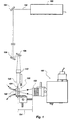
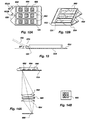
- a light source 100 provides a light beam 102 which is directed by means of mirrors 104, 106, 108 to an optical biosensor indicated generally at 120 (FIG. 1).
- light source 100 is an argon laser capable of emitting light at wavelengths of between about 488 and 514.5 nanometers (abbreviated nm).
- nm nanometers
- a laser diode emitting at wavelengths of 600 to about 700 nm can be used as light source 100.
- light source 100 may also be embodied as any other laser or other high-intensity light source emitting a sufficient amount of light at an appropriate wavelength to excite the selected tracer.
- FIG. 1 further includes a 45° angle mirror 110 which is positioned for making beam 102 a vertical beam prior to focussing the beam onto the biosensor.
- a 45° angle mirror 110 which is positioned for making beam 102 a vertical beam prior to focussing the beam onto the biosensor. It will be understood by those skilled that the number and arrangement of mirrors 104, 106, 108, 110 may be varied as necessary to accommodate various space limitations, with the sole requirement being that a sufficient amount of light be directed to biosensor 120.
- Biosensor 120 has an optical substrate 122 with one end 124 positioned to receive light from beam 102.
- a focussing lens 126 is positioned between angle mirror 110 and end 124 of waveguide 122, for focussing light from beam 102 onto end 124.
- Focussing lens 126 is here shown mounted on an X-Y translation unit so that its position may be adjusted for best focussing.
- optical substrate 122 is of generally planar shape having two planar surfaces spaced by a width, as shown in FIG. 2.
- Optical substrate 122 may for example be a square or rectangular glass microscope slide or coverslip, or the like. Materials for optical substrate 122 include glass, high-lead glass, quartz, optical plastic, and the like as are well-known in the art.
- Light detection means indicated generally at 150 are positioned to detect fluorescent light emitted from biosensor 120.
- the emitted light is reflective of the concentration of a selected analyte in a sample, as is better described subsequently in reference to FIGS. 2 and 7-10.
- Light detection means 150 includes a collection lens 152 positioned to collect the emitted fluorescence from a direction substantially orthogonal to the direct of propagation of light beam 102 through optical substrate 122.
- the distance 154 between collection lens 152 and optical substrate 122 is selected as known to those skilled to maximize the collection of light emitted from the region of evanescent light penetration.
- the light collected by collection lens 152 is then sent to detection means 150, which responds by outputting signals reflective of the level of collected fluorescence light.
- Detection means 150 may be any type of photodetector useful to detect light in the wavelength region spanning the wavelength range of the emitted fluorescence, as known in the art. However, in a preferred embodiment for simultaneous multi-analyte assays, detection means 150 is an imaging-type detector providing direct imaging of each of the fluorescent signal(s) originating in the evanescent zone 240. In the apparatus of FIG. 1, detection means 150 is a CCD (charge-coupled device) detector which produces a signal like that depicted in FIG. 4C. Such imaging signal collection provides simultaneous measurement of multiple samples in a much simpler way than a system in which a separate optical element is needed to read each well or patch. The present imaging detection system also provides for collection of emitted fluorescence directly from the evanescent zone 240 (FIG. 2), rather than via evanescent penetration of the fluorescence into the waveguide.
- FIG. 2 evanescent zone 240
- detection means 150 may be a photomultiplier, a semiconductor photodiode, or an array of such detectors.
- an array is generally preferable to a single detector for some purposes. With an array of small detectors, the user can determine that the peak fluorescence is being detected and is not inadvertently missed due to misalignment of the collection and detection optics.
- a grating spectrograph is coupled to the CCD or other detection means, to provide spectral analysis of the detected light. In that case, means are also provided to integrate the signal function around each peak to determine the total collected fluorescence from a sample.
- the spectrograph may be replaced by a filter which passes only wavelengths in the region of tracer fluorescence.
- FIGS. 14A and 14B depict an alternate and presently preferred embodiment of an imaging detection system, which may be substituted for the CCD imaging detector of FIG. 1.
- an array of photodiodes 680 is arranged with respect to a detection lens means such that light from a given patch is focussed onto a corresponding photodiode (FIG. 14A).
- the detection lens means comprises a pair of opposingly oriented lenses 682, 684.
- the apparatus having the imaging detection system of FIGS. 14A-B is substantially less expensive to make than one having a CCD detector.
- the patches 662, 664, 666 should be spaced appropriately to correspond to the size and spacing of the photodiodes, the focal length and magnification of the lens, and the distance between the waveguide surface. the detection lens or lenses, and the photodiode array, as generally understood in the art of optics.
- one or more filters 688 are positioned adjacent the detection lens, and preferably between two detection lenses as shown in FIG. 14B.
- This arrangement provides for effective filtering of scattered excitation light and other stray light prior to impingement of the signal light on the photodiodes.
- the filter(s) can be of either bandpass or long-pass type, and the wavelength region to be passed will depend upon the wavelengths of the excitation light and the fluorescent light of the tracer molecule. For example, with laser diode excitation at 635 nm of the cyanine dye CY5 which has peak fluorescence at 670 nm, filters passing light longer than about 650 nm in wavelength are useful. In a presently preferred embodiment, a bandpass filter centered at 670 nm with a 40 nm line-width is used.
- semi-cylindrical is defined to include both a transection of a right circular cylinder along a plane parallel to the vertical axis of the cylinder, and a transection of a right cylinder having bases of an elliptical shape.
- the lens shape may be similar to the type known as aspherical.
- a hyperboloid cross-section may also be suitable.
- the shape and dimensions of the curved surface of the lens should however be longitudinally uniform along the region used for focussing of the light beam.
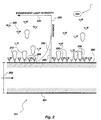
- optical substrate 124 is embodied as a planar waveguide having at least one planar surface 200 spaced from a second surface 201 by a width 202. At least surface 201 is disposed in contact with a sample solution 203. A plurality of capture molecules 204 are immobilized on surface 201.
- the sample solution contains a plurality of analyte molecules 210 of a selected analyte, and a plurality of tracer molecules 220.
- the capture molecules are chosen or constructed to bind to a binding moiety present on each of the analyte molecules 210.
- the tracer molecule 220 is chosen or constructed to emit fluorescent light in response to stimulation by light of the appropriate wavelength.
- the level of fluorescence emitted by the tracer molecules 220 is a measure of the amount of analyte bound to the capture molecule and is thereby reflective of the concentration of analyte molecules 210 in the solution.
- an evanescent light field is produced having an intensity curve 230 which drops off with distance from the surface 200, as diagrammed relative to a distance axis 232 and an intensity axis 234 (not to scale).
- An excitation zone 240 is the only region of the solution in which the evanescent light intensity is sufficient to excite a significant or detectable fraction of tracer molecules 220 (not to scale). Tracer molecules 220 outside zone 240 will contribute little or no induced fluorescence. Excitation zone 240 is typically between about 1000 and 2000 ⁇ in depth.
- Capture molecules 204 may be whole antibodies, antibody fragments such as Fab' fragments, whole antigenic molecules (haptens) or antigenic fragments, and oligopeptides which are antigenic and/or similar in 3-dimensional conformation to an antibody-binding epitope.
- Capture molecules 204 may also be a receptor molecule of the kind usually found on a cell or organelle membrane and which has specificity for a desired analyte, or a portion thereof carrying the analyte-specific-binding property of the receptor.
- FIG. 2 a competition assay scheme is depicted (also termed a displacement assay).
- a displacement assay also termed a displacement assay.
- alternate assay schemes such as sandwich assays may be performed with the present apparatus.
- the capture molecules 204 may be immobilized on the surface 202 by any method known in the art. However, in the preferred embodiment the capture molecules are immobilized in a site-specific manner. As used in this application, the term "site-specific" means that specific sites on the capture molecules are involved in the coupling to the waveguide, rather than random sites as with typical prior art methods. Examples I-III detail methods for site-specific immobilization of capture molecules to the surface of the optical substrate by means of a protein-resistant coating on the substrate.
- the intensity of evanescent light drops off rapidly with distance from the waveguide surface.
- the range 240 is generally about 1000 to 2000 ⁇ . This range is sufficient to ensure that essentially all tracer molecules 220 which are bound (directly or indirectly) to capture molecules 204, will be detected, while the bulk of the tracer molecules which remain free in solution are outside the effective excitation range.
- light source 100 is an argon ion laser (a LEXEL Model 95-2) at an emission wavelength of 514 nm. Fluorescence detection was done with a monochromator (SPEX Industries, Inc., Model 1680C) and a charge-coupled device (abbreviated CCD) (Photometrics Ltd. Series 200, or CH-250).
- CCD charge-coupled device
- light source 100 can be any light source emitting at the wavelength desired for excitation of selected fluorescent dyes.
- the detection means may be simplified in accordance with the minimum requirements of the assay.
- light source 100 is a laser diode emitting in the red wavelength region of 600-700 nm, available from Toshiba (model No. TOLD 9211) This laser diode provides about 5 milliwatts of power with a peak emission wavelength of about 670 nm. Laser diodes emitting at 630 nm are also available and can be used. For an embodiment using a wavelengths in this region, it is necessary to use dyes such as cyanine dyes, whose fluorescence can be stimulated by excitation with wavelengths in the red spectral region. An example of such a dye is CY5, available from Biological Detection Systems, Inc., Pittsburgh PA (catalog no. A25000).
- the CY5 dye can be conjugated to the desired tracer molecule by the manufacturer's instructions and/or with a kit available from BDS.
- a second dye, CY7, which is available from the same source may also be suitable.
- the dyes and methods for conjugating are also characterized in the paper by Southwick, P.L., et al., titled "Cyanine Dye Labelling Reagents - Carboxymethylindo-cyanine Succinimidyl Esters", Cytometry 11 :418-430 (1990).
- the use of laser diodes as a light source permits the biosensor and waveguide to be formed of plastic, which considerably reduces the expense of manufacture and facilitates the integral molding of the semi-cylindrical lens with the waveguide and reservoirs.
- the immunoassay is a competition assay in which the tracer molecules 220 are constructed such that capture molecules 204 will bind tracer molecules 220 in place of analyte molecules 210.
- Higher concentrations of analyte molecules 210 will cause most of the tracer molecules 220 to be displaced into the surrounding solution from capture molecules 204, thus reducing the number of tracer molecules within excitation range 240 of the substrate 122. This reduced binding of tracer molecules in turn reduces the amount of fluorescence.
- lower concentrations of analyte molecules 210 will allow tracer molecules 220 to bind to capture molecules 204, and thus to be held within the excitation range 240.
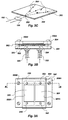
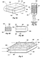
- biosensor 120 is shown as a flow-through cell, shown in greater detail in FIGS. 3A-B.
- a planar waveguide 302 which may be for example a microscope slide or coverslip, is sandwiched between two plates 304, 306 which are held together by screw fittings 308A, 308B.
- a gasket 320 is seated between waveguide 302 and plate 306.
- Gasket 320 is configured with two internal openings which, when gasket 320 is securely sandwiched between plate 306 and waveguide 302, form reservoirs 322, 324.
- reservoirs 322, 324 waveguide 302 constitutes one wall, plate 306 constitutes a second wall, and the inner edges 322A, 324A of the gasket form the remaining walls.
- the reservoirs 322, 324 are here shown to be rectangular in shape, other shapes could be used.
- the gasket could have either just one opening or more than two, creating corresponding numbers of individual reservoirs.
- Gasket 320 is preferably made of a semi-rigid material having an index of refraction less than that of the waveguide material in the wavelength range of the exciting light. For best results, it is believed that the index of refraction of the gasket material should be as low as possible compared to that of the waveguide. For a waveguide made of quartz or glass the index of refraction would typically be from about 1.46 to 1.52, higher for high-lead glass.
- a transparent (non-pigmented) silicon rubber (siloxane polymer) with an index of refraction of 1.35-1.43 is a presently preferred material for gasket 320.
- TEFLON-type materials such as PTFE (polytetrafluoroethylene) or FEP (fluorinated ethylene propylene) have indices of refraction of around 1.34-1.35, and may also be suitable. However, because TEFLON surfaces tend to adsorb protein in a non-specific manner, silicon rubber is generally preferred.
- the lower plate 306 in FIG. 3B has a pair of inlets 330, 332 and a pair of outlets 340, 342. These inlets and outlets are arranged so as to permit solutions to flow separately through the respective reservoirs 322, 324. Desirably, the lower plate 306 may be made from aluminum alloy.
- FIG. 3C shows the waveguide 302 in isolation from the remaining parts of the biosensor.
- Lens 126 is shown receiving and focussing light beam 102 onto the waveguide.
- the outer, surrounding edge 350 is coated with a reflective material, except for an uncoated region 352 at which the focussed light from lens 126 enters the waveguide (FIG. 3C).
- Arrows 354 indicate reflection from the coated edges. In FIG. 3C, only one lens and one uncoated region are shown, however, for two or more channels, more portions of edge 350 may be left uncoated to allow light to enter the waveguide (see for example FIG. 4A).
- the reflective coating reflects back into the waveguide, light that would otherwise escape through the edge 350.
- the intensity of the evanescent light wave is thereby enhanced.
- Suitable reflective coating materials include aluminum, silver, or the like, as known in the art.
- reflectors could be positioned about the edges to reflect escaping light back into the waveguide.
- the design with at least two individual reservoirs has significant advantages over a single reservoir embodiment for instances in which it is desirable to measure the test sample fluorescence simultaneously with fluorescence from a control region on the same waveguide. For example, the level of non-specific binding to the waveguide can be subtracted from the test sample fluorescence. Also, measurement changes due to fluctuations in intensity of the exciting light can be corrected for.
- the "control" region could be the pre-loaded waveguide with no analyte present in the sample, or with a known amount of analyte. With three or more wells, fluorescence can be measured for both a no-analyte control and at least one known, calibration analyte sample in addition to the "unknown" or test sample.
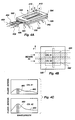
- Fig. 4A depicts the flow-through cell of FIGS. 3A-3B as it would be used for a waveguide excitation protocol.
- the light beam is split into two equal components 400, 402 passing through respective focussing lenses 404, 406 to illuminate "channel 1" (CH.1) and "channel 2" (CH.2) in the waveguide 302.
- Solid arrows 410 indicate the direction from which fluorescence in CH.1 is collected, while dashed arrows 412 indicate the direction from which fluorescence in CH.2 is collected.
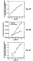
- FIG. 4B depicts hypothetical expected results from such a detection system for simultaneous measurement of a "blank" or no-analyte sample in CH.1 and a test sample or "unknown" in CH.2.
- Curves 450, 452 respectively represent the fluorescence from CH.1 and CH.2.
- the fluorescent intensities of the blank and the sample would be compared by means of the values of the corresponding integrals of curves 450, 452 over the respective regions 460, 462.
- a calibration curve for a series of calibration samples of known analyte concentrations would typically be made and used to determine the concentration of an unknown sample, as known in the art.
- FIG. 4A Of further interest in FIG. 4A is the orientation of lenses 404, 406 with respect to waveguide 302. It will be seen that the curved edges 404A, 406A face towards waveguide 302, which is 180° from the orientation depicted in FIG. 3C. While the focussing lens can be oriented in either way, the arrangement of FIG. 4A is presently preferred for illumination of the waveguide with the flow-through cell.
- FIGS. 5A-5D depict an alternate embodiment of a biosensor useful with the apparatus of FIG. 1.
- the biosensor indicated generally at 500 has an integrally mounted or formed focussing lens 502 and waveguide 504 arranged such that lens 502 focusses light onto the forward end 506 of the waveguide.
- Focussing lens 502 is configured and positioned to focus a light beam onto the receiving end 506 of the waveguide 504 (FIGS. 5A, 5C).
- Side walls 511, 512, top and bottom walls 516, 517, and a removably sealing rear wall 518 enclose the space about the waveguide 504 to create reservoirs 520, 522.
- the integral focussing lens 502 replaces focussing lens 126 in the apparatus of FIG. 1.
- the focussing lens is molded as part of the waveguide holder 500 of an optical plastic such as polystyrene, polycarbonate or the like.
- Biosensor 500 also includes reservoirs 520, 522 best seen in FIGS. 5B, 5C and 5D in which sample solutions can be disposed.
- reservoirs 520, 522 best seen in FIGS. 5B, 5C and 5D in which sample solutions can be disposed.
- FIG. 6 depicts an alternate multiwell biosensor similar to that of FIGS. 5A-5C, except that a series of discrete wells 600, 602, 604, 606 are formed on the waveguide 504.
- the embodiment of FIG. 6 would be used in a horizontal position, so that the wells 600, 602, 604, 606 need not be covered.
- the biosensor including the lens may be formed by molding of a suitable optical plastic.
- a holder comprising the reservoir walls, the lens, and frame elements as needed, may be pre-molded.
- a silica-surface waveguide is inserted subsequently with a refractive-index-matched adhesive to secure it in place and seal it as needed to create separate channels.
- the holder may be molded with a silica-surface waveguide in place, thereby eliminating the need for the adhesive.
- the waveguide is also formed of the optical plastic and is molded simultaneously with the lens and/or the reservoirs.
- the latter type construction is not suitable for use with excitation wavelengths of 488 to 515 nm, because known optical plastics tend to emit fluorescence when excited in this (the blue and green) wavelength region. This fluorescence would appear as background fluorescence.
- an alternate embodiment of the apparatus using a light source emitting at wavelengths of 600 nm and above would accommodate a plastic waveguide. Molding the lens/wave-guide, or lens/waveguide/reservoir(s), as a single unit of plastic substantially reduces the cost of manufacturing and makes a disposable biosensor more feasible.
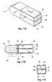
- FIGS. 11A-C shows another embodiment of a biosensor similar to that depicted in FIGS. 3A-C.
- waveguide 10 is a glass coverslip inserted in a sawcut groove 12 (FIG. 11B) in a solid, colorless plastic lens 14.
- Transparent walls 16, 18, 20, 22 are sealingly attached with index-matched adhesive to the lens 14 and about the edges of the waveguide 10 to form a pair of separate reservoirs 30, 32 (FIG. 11B).
- the curved forward edge 34 of the lens 14 is spaced at a distance 40 from the forward end of the waveguide 10.
- Distance 40 is selected so as to match the focal length of the lens 14.
- the embodiment of FIGS. 11A-C can be used in a vertical orientation as shown in FIG. 5C.
- the biosensor may be oriented with the waveguide 10 in a substantially horizontal position, so that only one side of the waveguide 10 is used. In such case, a cap which can sealingly close the open ends of the reservoirs must also be provided.
- An advantage of the horizontal orientation scheme is that only a thin layer 50 of sample solution is required (FIG. 11C). However, unless ribs along the waveguide 10 are provided, like ribs 530 in FIG. 5D, the biosensor of FIG. 11C in the horizontal orientation has only one effective sample channel.
- curved edge 34 of lens 14 is shown as being substantially a semi right-cylinder in shape, other lens shapes are possible as described previously herein with respect to FIGS. 3A and 5C.
- the end of the planar waveguide which is distal to the receiving edge has a portion 650 of serrated or toothed shape.
- the angles 652A, 652B must be less than the critical angle for total internal reflection at the waveguide-air interface (the critical angle for polystyrene/air is about 51°).
- the increased TIR enhances the evanescent field intensity and thus improves sensitivity of the assay.
- the serrated end edge helps to equalize (make more uniform across the whole waveguide) the intensity of light within the waveguide.
- the entire waveguide portion of the biosensor should have an optical-quality surface, including the serrated end and the integral lens.
- the waveguide is about 0.05 centimeters (cm) in thickness and the wells are about 0.08 to 0.1 cm in depth.
- the biosensor including the waveguide is about 2.5 cm wide and about 4.3 cm long.
- FIGS. 12A and 12B also has a plurality of parallel wells 660 each extending along the longitudinal direction from the light receiving end 124 of the waveguide.
- each well contains a plurality of patches 662, 664, 666 each comprising a different immobilized Fab' species.
- the increased sensitivity results from 1) avoiding leakage of waveguide light through the walls, and 2) avoiding scattering of the excitation light which may excite unbound tracer molecules outside the region of evanescent penetration, undesirably increasing background fluorescence.
- the sheet excitation beam is arranged to enter the receiving edge of the waveguide at an angle to the plane of the waveguide.
- FIG. 13 shows an angled integral lens 670 configured to accept such angled beam entry.
- the beam originating from the laser should be shaped to a sheet of width approximating the width of the receiving region of the waveguide, and of relatively narrow thickness (preferably no more than tenfold, and preferably one- to four-fold the waveguide thickness), using cylindrical and/or spherical lenses as known in the art.
- the mean beam entry angle is selected to be less than, but near the critical angle of the waveguide/solution interface. The closer the beam entry angle is to this critical angle, the greater the increase in evanescent intensity. However, a beam entry angle too near the critical angle could result in some of the entering light escaping at the waveguide/solution interface, thus decreasing the waveguiding efficiency and evanescent intensity. Thus, there is an optimum angle that can be determined experimentally. Generally, a beam entry angle of a few degrees less than the critical angle (from about 5 to about 15 degrees less), will be useful
- the critical angle is about 33°, and the presently preferred beam entry angle is 25°; with these values, an increase in evanescent light intensity of at least about a factor of two is achieved over using a 0° beam entry angle.
- the integral lens/waveguide may be formed as shown in FIG. 13.
- the following examples detail several methods for attaching the capture molecules to the waveguide surface in a site-specific manner.
- the general scheme for reducing the level of non-specific binding is to coat the waveguide with a protein-resistant material, and then immobilize the antibody to the coating.
- the scheme further includes derivatizing of the protein-resistant coating combined with site-specific modification of the antibody or other capture molecule to be immobilized, so as to provide site-specific attachment of the capture molecule to the coating.
- Example II the procedures of Examples I and II gave generally better results.
- the avidin-biotin coupling method (Example II) is the most preferred. Using either coupling scheme, at least about 75% of the immobilized Fab' fragments were active, and the levels of non-specific binding were typically no more than 1-2% of the specific binding.
- the modified PEG coating gave slightly higher levels of non-specific binding, in the range of 5 % to about 25 %.
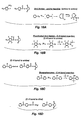
- a silica surface was prepared with a hydrogel coating comprised of polymethacryloyl hydrazide (abbreviated PMahy).
- the surface was derivatized with aldehyde groups.
- the derivatization was accomplished by silanization with 3-aminopropyltriethoxy silane (abbreviated APS) to add an amino functional group, followed by reaction with glutaraldehyde to produce free aldehyde groups.
- APS 3-aminopropyltriethoxy silane
- the PMahy was then be reacted with these aldehyde groups to form the hydrogel coating.
- Antibodies could be coupled to this hydrogel in at least two ways.
- the carbohydrate groups in the Fc antibody region are oxidized to aldehydes by treatment with sodium metaperiodate.
- few antigen-binding fragments contain carbohydrate moieties useful for this purpose.
- a preferred method comprised modifying the pendant hydrazido groups of the hydrogel to a maleimido group by treatment with succinimidyl 4-(N-maleimido-methyl)cyclo-hexane-1-carboxylate (abbreviated SMCC; Pierce Chemicals).
- SMCC succinimidyl 4-(N-maleimido-methyl)cyclo-hexane-1-carboxylate
- PMaCl Polymethacryloylchloride
- MaCl methacryloyl chloride
- the mixture was then diluted with twice the amount of dioxane used in the reaction and slowly added to an excess of hydrazine hydrate, to achieve a volumetric ratio of 2:5 for diluted PMaCl.
- the latter addition was carried out for about 30 minutes in an ice bath under a nitrogen atmosphere.
- the resulting mixture was then stirred for about an hour at room temperature.
- the product PMahy was purified by evaporation of dioxane and the remaining unreacted hydrazine hydrate, followed by washing in distilled water. The washed product was then dialyzed in a SpectraPor dialysis membrane having a molecular weight cut-off of 3,500 daltons, to remove unreacted monomer.
- the polymer so prepared was shown to have a molecular weight of about 26,000 as measured by gel permeation chromatography for the hydrochloride form.
- the concentration of polymer in solution in the hydrochloride form was estimated to vary between about 5% and 8% (w/v). It has been found that the polymer can be stored in aqueous solution at 4°C under a nitrogen atmosphere, for at least 5 months without undergoing a detrimental amount of spontaneous cross-linking.
- Silica chips or glass or quartz microscope slides were cleaned with chromic acid, then treated with 5 % APS/95 % deionized water (v/v) for about fifteen minutes at room temperature.
- the APS-treated surfaces were rinsed with deoionized water and absolute ethanol, and incubated in a vacuum oven which had been flushed at least three times with nitrogen, at 120°C for 1 hour.
- the resulting silanized surfaces were then soaked in 2.5% glutaraldehyde (E.M. grade from Polysciences) in 0.1M carbonate-bicarbonate buffer, pH 9.2, for two hours at room temperature.
- linear PMahy was reacted with the aldehyde groups on the treated chips to create a cross-linked polymer film with many unreacted hydrazido groups in the chains. This was done by dipping the treated chips in solutions of PMahy of between about 5% and 8% (w/v), pH 5.2, at a temperature between about room temperature and about 60°C, for a time sufficient to form a polymer film of thickness about 100 ⁇ or less.
- the thickness of the hydrogel layer increases with time and temperature of incubation in the solution. It was found that optimal conditions for preparation of the film of 100 ⁇ thickness or less, comprised incubating in 5% (w/v) PMahy for 2 hours at room temperature (about 25°C).
- the free hydrazido groups of the polymer film were modified by treatment with SMCC to provide reactive maleimido groups on the ends of the polymer side chains. This was done by immersing the PMahy-coated substrates in a solution of 0.19% (w/v) SMCC in dimethylformamide for about 1 hour at 25 °C.
- the hydrogel-coated surfaces were treated with a 1 mg/ml solution of Fab' fragments in phosphate buffer, ph 6.0, with 5 mM EDTA.
- the waveguide surface so prepared was shown to immobilize Fab' molecules at a surface density of about 1.4 x 10 -12 moles/cm 2 .
- the surface was able to immobilize Fab' fragments at their C-terminal thiol groups in a site-specific way.
- the thickness of the resulting polymer film was determined by ellipsometry to be about 100 ⁇ , as was desired. This film thickness is much less than typical previous polymeric films, which have thicknesses of 0.35 to 25 ⁇ m (microns).
- the Fab' fragments were coupled to the free maleimido groups pendant from the polymer-coated surface as follows.
- the prepared waveguide surface was incubated for 24 hours at 4°C in a solution containing the Fab' fragments at a concentration of 1.5 x 10 7 molar, in a phosphate buffer with 5 mM EDTA (pH 6.0).
- biotin-Fab' conjugates also referred to as biotinylated Fab' fragments or b-Fab' fragments.
- biotin-Fab' conjugates also referred to as biotinylated Fab' fragments or b-Fab' fragments.
- the biotin is coupled at specific location(s) on the Fab' fragments.
- the avidin coated surface is then treated with the b-Fab' fragments, so that the biotin binds to the avidin thereby immobilizing the Fab' fragment to the surface in a site-specific manner.
- Biotinylated Fab' conjugates were prepared from a solution of Fab' fragments in PBS (0.5-1 mg/ml), by addition of a sufficient amount of 4 mM biotin-HPDP in dimethyl-formamide to provide a 20-fold molar excess of biotin-HPDP. This mixture was incubated for 90 minutes at room temperature, and biotinylated Fab' fragments (abbreviated b-Fab') were purified by gei permeation chromatography with Sephadex G25 equilibrated in PBS.
- the oxidized Mab 9-40 was purified by gel filtration chromatography on Sephadex G25 equilibrated with 0.1M sodium acetate buffer pH 5.5, and then reacted with 5 mM biotin-LC-hydrazide for 2 hours at room temperature with agitation. Unreacted biotin-LC-hydrazide was removed using a Sephadex G25 column equilibrated in PBS.
- Avidin-coated surfaces were immersed in a 1.5 x 10 -7 M solution of b-Fab' fragments for about an hour at room temperature, followed by washing with PBS to remove unbound b-Fab' fragments.
- PEG polyethylene glycol
- PEG polyethylene glycol
- the density of immobilized Fab' fragments obtained using the avidin-biotin coupling chemistry was about 1.4x10 -12 moles per cm 2 (square centimeter).
- the terminal hydroxyl groups of polyethylene glycol were converted to primary amine or hydrazide groups by reaction with ethylenediamine (abbreviated ED) or hydrazine (abbreviated HZ), respectively, to produce PEG-ED 2 or PEG-HZ 2 .
- the PEG molecules so modified were then coupled to APS-glutaraldehyde activated silica surfaces.
- One ED moiety on each PEG-ED 2 molecule couples to a free aldehyde group on the silanized-glutaraldehyde-treated waveguide surface.
- the other ED or HZ, if PEG-HZ 2 is used
- a capture molecule binding protein
- Monofunctional (PEG M2000, M5000) or difunctional (PEG 3400, PEG 8000, PEG 18,500) of the indicated molecular weights in daltons were reacted with p-nitrophenyl chloroformate (abbreviated p-NPC; obtained from Aldrich Chemicals) in solution in benzene.
- p-NPC p-nitrophenyl chloroformate
- the mixture was agitated at room temperature for about 24 hours.
- Dry ethyl ether (less than 0.01% water, purchased from J.T. Baker Chemicals) was used to precipitate PEG-(o-NP) 2 from solution. The precipitate was vacuum-dried overnight.
- PEG-Onp Between about 50% and about 100% of PEG molecules were converted by this treatment to PEG-Onp, as determined by hydrolysis with 0.1N sodium hydroxide to release the p-nitrophenol groups.
- the absorbance at 402 nm was determined spectrophotometrically and a molar extinction coefficient of 18400 M -1 cm -1 used to determine the amount of conversion.
- the level of conversion depended somewhat on the molecular weight of the PEG of MPEG.
- PEG-(o-NP) 2 was then dissolved in ethylenediamine and agitated gently for about 3 hours at room temperature.
- the PEG-(ED) 2 was then precipitated by addition of a sufficient amount of dry ethyl ether.
- the yellow PEG-(ED) 2 solution was decolorized by addition of 1 drop of 12N (normal) hydrochloric acid. and the precipitation with ethyl ether repeated twice more.
- the wet PEG-(ED) 2 was dried under vacuum overnight.
- the PEG was derivatized with hydrazine to produce PEG-Hz 2 .
- the modified PEG was coupled to silanized-glutaraldehyde-treated waveguide surfaces prepared as described in Example I.
- the prepared waveguide surfaces were immersed in the PEG-ED solution and incubated at 60°C for about 24 hours.
- the procedure using K 2 SO 4 -acetate buffer yielded a higher density of PEG molecules attached to the surface than that using PBS buffer.
- Antibodies or other binding proteins were immobilized to the PEG-coated waveguides as follows.
- a solution of about 3 mg/ml of antibody was dissolved in 0.15 M sodium acetate buffer, pH 5.2.
- a solution of equivalent weight of 50 mM sodium metaperiodate (NaIO 4 ) was then added, and the reactants were agitated at room temperature for about an hour. Unreacted sodium metaperiodate was removed by passing the reaction mixture through a desalting column (type PD-10 from Pharmacia), which had been pre-equilibrated with the sodium acetate buffer.
- the PEG-coated waveguides were then incubated with the oxidized antibody solution in the sodium acetate buffer, pH 5.2, for 3 days at 4°C, then rinsed to remove unbound antibody.
- Absolute antigen binding was determined by means of radiolabelled tracers or capture molecules.
- radiolabelled BSA-FL 9 was allowed to be coupled with immobilized Fab' fragments for 5 or 60 minutes in phosphate buffer pH 7.3 at room temperature. The tracer concentration was 1.5x10 -7 M.
- Three ml per sample of fluorescein-labelled BSA (BSA-FL 9 ) at concentrations ranging from 10 -10 M to 10 -7 M was injected into the flow cell. The injection was performed over a five-minute interval. The spectrum at wavelength of 488 nm was taken and the bulk BSA-FL 9 was removed by flushing with PBS buffer. Three more spectra were taken, and the fluorescein peak from 513 to 517 nm was integrated. These values were set versus the log of BSA-FL 9 concentration in order to obtain the binding isotherm.
- the coated silica chips with either immobilized radiolabelled capture molecules or with labelled tracer molecules bound to unlabelled capture molecules were washed thoroughly in a suitable buffer and counted on a gamma counter.
- 125 I-labelled antibodies or antigens were preferred for the radiolabelling, which was done using the Chloramine-T method (see Greenwood et al., Biochem. J. 89 :114-123 (1963)).
- the percentage of immobilized molecules that were active was also considerably higher for avidin-biotin and for hydrogel coupling chemistries, being in the range of 50% to 75% for Fabs.
- the row labelled silica-avidin with biotin-PEG represents data obtained with the further refinement of preloading the surface (after attachment of the capture molecules) with biotin-PEG conjugates. This was done to passivate potential non-specific binding regions. However, the improvement obtained with biotin-PEG preloading was not large.
- anti-hCG murine anti-human chorionic gonadotrophin
- the parent monoclonal antibody was purified as described by van Erp et al. J. Immunol. Methods, 140 :235-241 (1991).
- This mouse antibody termed anti-hCG-A, is directed against a portion of the ⁇ -subunit of hCG (provided by Organon-Teknika of Boxtel, Netherlands).
- the whole monoclonal antibody anti-hCG-A was used in the experiments whose results are depicted in FIGS. 7A, 7B, 8, 9A-9F, and 10A-10D.
- F(ab') 2 fragments were produced by digestion with pepsin using the procedure described by Grey and Kunkel, "H Chain subgroups of myeloma proteins and normal 7S globulin," J. Exp. Med. 120 :253-266, 1964. Following digestion, F(ab')2 fragments were reduced to Fab' fragments using dithiothreitol (DTT). Specifically, 33 mg of purified antibody and 1 mg pepsin (Sigma) were dissolved in 0.1 M sodium acetate buffer (pH 4.2) and the digestion was carried out at 37°C for 16 hours. The digestion was terminated by adjusting the pH of the reaction mixture to 8.0 with 2 M tris base.
- DTT dithiothreitol
- the F(ab') 2 fraction was separated by gel permeation chromatography (Superdex Hiload, Pharmacia) using phosphate-buffered saline (PBS), pH 7.7, as eluent.
- Fab' fragments were prepared by reducing the F(ab') 2 fragments (1 mg/ml) with 1.75 mM DTT and 3.5 mM ethylenediamine tetraacetate (EDTA) in 0.17 M tris buffer (pH 7.4) for 45 minutes at room temperature. After reduction, excess DTT was removed by gel permeation chromatography using a Sephadex G-25 column (Pharmacia) equilibrated in 0.1 M sodium phosphate buffer (pH 6.0) containing 5 mM EDTA.
- FIGS. 7A, 7B, 8, 9A-9F, and 10A-10D and Tables I-III were performed using an interfacial fluorometer constructed at the University of Utah.
- Silica waveguides with the appropriate respective immobilized antigens were placed in the dual-channel flow-cell of FIGS. 3A and 3B.
- the two channels were used for sample and reference measurements, as described with respect to FIGS. 4A-C.
- the light source was the 514.5 nm emission of an air-cooled argonion laser.
- the laser beam was split into two parallel beams, which were focused with lenses into the two channels of the waveguide.
- Fluorescence emission was recorded from 520 to 620 nm using a monochromator connected to a computer-controlled CCD camera.
- the fluorescence spectrum was integrated from 560 nm to 600 nm to improve the signal-to-noise ratio.
- FIGS. 7A, 7B and 8 are charts depicting fluorescence intensity data obtained using two alternate formats for performing a fluorescence immunoassay to detect an antibody.
- hCG human chorionic gonadotrophin
- the antibody to be detected was chosen to be a monoclonal antibody (designated anti-hCG-A) to an hCG antigen (the latter designated hCG-A).
- the data of FIG. 7A were obtained with whole hCG molecules serving as the capture molecules (the antigen or analyte binding molecule) in the assay.
- the data of FIG. 7B were obtained using an oligopeptide constructed to selectively bind the anti-hCG-A antibody, as the capture molecules. Oligopeptides suitable for this purpose for any known antigenic analyte molecule analyte can be obtained using the methods of Geysen et al.
- the N-terminus of the oligopeptide was modified to provide an amino group for amino-reactive dyes, or the C-terminus was modified to provide a cysteine thiol group for thiol-reactive dyes).
- the complete oligopeptide sequence is of length sufficient that the attached dye is spaced from the binding site by at least two or three residues.
- the tracer was a goat anti-mouse IgG labelled with tetramethylrhodamine (abbreviated TMR).
- TMR tetramethylrhodamine
- the capture molecule was biotinylated as described in Example II and immobilized on an avidin-coated silica substrate.
- the test antibody, anti-hCG A was premixed with the tracer (goat anti-mouse IgG-TMR) in the test solution.
- FIGS. 7A and 7B were obtained with the following protocol. Different concentrations of anti-hCG A were premixed with the tracer antibody (concentration fixed at 10 -8 M) and injected into the sample channel. A 10 -8 M concentration of tracer antibody was also injected into the reference channel as a control. The fluorescence intensity of the sample channel was plotted vs. anti-hCG A concentration and the fluorescence intensity of the reference channel was also plotted on the same set of axes (this is really a plot of the non-specific binding of the tracer antibody vs. time, since no anti-hCG A was injected into the reference channel).
- FIGS. 7A and 7B show the results for a sandwich assay format following the binding of anti-hCG A to immobilized hCG and to the oligopeptide, respectively.
- Figure 8 shows the corresponding fluorescence enhancements for both cases.
- the data from FIGS. 7A and 7B were normalized for background fluorescence and replotted as fluorescence enhancement (F sample /F reference ) versus log analyte concentration.
- the response curve was similar for both of the immobilized antigens (whole hCG and oligopeptide antigen) over a range of antibody concentrations from 10 -13 M to 10 -10 M. However, whole hCG gave better precision.
- analyte levels as low as 10 -13 molar were detectable with the assay.
- the tracer antibody concentration is reduced to 10 -10 M or less. This is expected to reduce background fluorescence due to non-specific adsorption of the tracer antibody and thereby further improve the sensitivity to 10 -14 M or better.
- FIGS. 9A-9C depicts data obtained using an antibody as the capture molecule to detect an antigen, in a sandwich-type assay.
- two different antibodies are employed in a sandwich immunoassay ⁇ an immobilized capture antibody and a labelled tracer antibody in solution. Since the capture antibody and the tracer antibody must bind to distinct regions of the antigen, two different monoclonal antibodies which bind to different epitopes on the antigen are typically used in such assays.
- three other monoclonal anti-hCG antibodies (anti-hCG-B, anti-hCG-C and anti-hCG-D, respectively) were obtained from Organon Teknika which bound to different epitopes than did anti-hCG-A. Since only anti-hCG A is specific to hCG (the others also bind to certain hormones related to hCG), only six of the twelve possible pairwise combinations of antibodies provide strict selectivity for hCG.
- FIGS. 9A-F depict results obtained with different pairwise combinations, with Fab' fragments prepared from anti-hCG A (Fab'-A) and immobilized to waveguides using the avidin-biotin coupling chemistry.
- Fab' fragments prepared from anti-hCG B, anti-hCG C and anti-hCG D were labeled with tetramethylrhodamine for use as tracer antibodies (designated Fab'-B, Fab'-C and Fab'-D, respectively).
- FIGS. 9A and 9B show results with Fab'-B as the tracer molecule.
- FIGS. 9C, 9D show results obtained using Fab'-C as the tracer molecule.
- FIGS. 9E, 9F show results obtained using Fab'-D as the tracer molecule.
- Fab'-B and Fab'-C are preferred for use as tracers in an hCG assay.
- FIGS. 10A-D show data obtained from a competition or displacement assay.
- Fab'-A fragments were immobilized to waveguides using either the avidin-biotin chemistry (FIGS. 10A, 10B) or the hydrogel coupling chemistry (FIGS. 10C, 10D).
- the immobilized Fab'-A fragments were preloaded with the tracer oligopeptide at a concentration of 10 -8 M.
- concentrations of hCG were added to one channel of the flow cell (sample) and PBS buffer was added to the other (reference).
- the raw fluorescence intensities of the sample and reference channels are shown in the panels on the left (10A & 10C) and the percent of full-scale fluorescence (in the absence of hCG) are shown in the panels on the right (10B & 10D).
- the latter values were normalized for the change in reference fluorescence. Standard errors were plotted for all data points, but in some cases were smaller than the plot marks.
- the sandwich immunoassay is preferred for several reasons. First, detection of concentrations down to at least 0.1 picomolar can be demonstrated, as compared to picomolar concentrations for the competitive assay. Also, the instant sandwich immunoassay was capable of detecting concentrations ranging over five logs - from 10 -8 M to 10 -13 M. Thus, a single assay formulation using the sandwich procedure could serve for a variety of applications where different detection limits are required.
- a further embodiment of coating chemistry provides for photo-activated coupling of the binding moiety (Fab fragment, antibody or whatever) to the waveguide surface.
- the photoactivation process By combining the photoactivation process with localized irradiation (for example, by masking), it is possible to sequentially couple different binding species to different regions of the waveguide surface.
- a waveguide surface patterned with patches each of a different capture molecule species (Fabs or Fab fragments) can be conveniently produced, without need for walls between the different species.
- the coating chemistry also "passivates" the surface, that is, inhibits nonspecific binding of the fluorescent tracer, and thus reduces the background signal.
- a presently preferred coating is a type of compound referred to herein as a "block copolymer”, comprising at least one hydrophilic block containing polymerized hydrophilic residues (polyethylene oxide, "PEO"), adjacent at least one hydrophobic block containing polymerized hydrophobic residues (polypropylene oxide, "PPO").
- a subclass of such compounds referred to herein as “triblock copolymers” or “TBCPs” comprise a hydrophobic block flanked by hydrophilic blocks.
- a series of TBCPs are commercially available from BASF Corporation under the tradename PLURONICS.
- PPO polyethylene glycol
- PEO polystyrene
- Block copolymers have the general property of inhibiting non-specific protein adsorption, while providing hydrophilic side chains useful to attach proteins, including Fabs or Fab fragments.
- a general procedure for preparing a patterned polystyrene waveguide is as follows. First, a waveguide surface 700 coated with PF108 molecules 702 is prepared. Next, the free PEO chain ends 704 of the PF108 molecules 702 in a selected region of the waveguide are derivatized in a photo-activated coupling reaction with a photoaffinity crosslinker 706.
- Suitable crosslinkers are heterobifunctional reagents which have a photo-activatable group conjugated to a reactive functional group such as isothiocyanate, succinimide or maleimide.
- the photo-activatable groups of the crosslinker 706 react to covalently bind to the free PEO chain ends 704.
- a mask 712 confines the irradiation to a first region 714 of the waveguide.
- the result is waveguide surface having reactive functional groups useful to bind Fab' fragments only in the first region 714.
- the waveguide surface is incubated with a solution of Fab' fragments of a first species (FAB 1 720 in FIG. 16) for a time sufficient to allow the binding of Fab' fragments to the derivatized region to go to completion.
- the unreacted Fab' fragments are then washed off, and the process of photo-activated derivatization is repeated for a second region of the waveguide, followed by incubation with a second species of Fab' fragment.
- incubation with a solution of Fab' fragments can be performed substantially as described for the PMahy coating.
- the Fab' fragments 720 are coupled to the crosslinker 706 before the crosslinker is photo-reacted with the PEO chain ends 704 (FIG. 17).
- This embodiment is presently preferred because the surfaces thus prepared are capable of binding larger levels of analyte plus tracer per unit area than those prepared according to the protocol of FIG. 16.
- Suitable photoaffinity crosslinkers include aryl azides (amine-to-amine linkage), fluorinated aryl azides (C-H bond-to-amine linkage), and benzophenones (C-H bond-to- amine linkage or C-H bond-to-thiol-linkage, depending on the specific compound). Examples of each type are shown in FIGS. 18A-18D, along with the corresponding photo-activated coupling reaction. Presently, benzophenones providing a C-H bond-to-thiol linkage are preferred, as these can be used to achieve site-specific coupling to Fab' fragments.
- BPIA iodoacetamide
- BPM maleimide derivatives of benzophenone
- BPM is preferred, as it exhibits a higher degree of specific binding and a lower degree of non-specific adsorption. This is because the coupling occurs via the C-terminal thiol groups of the Fab' fragments, as described previously herein for the PMahy coating.
- Other photo-affinity crosslinkers providing free maleimido groups may be equally suitable.
- the amount of crosslinker coupled to the PF108 depends on the duration and intensity of the irradiation, the concentration of crosslinker molecules, etc. These variables can easily be tested and optimized to find parameters which will achieve a desired level of crosslinker and/or Fab' protein coupled to the waveguide surface. Generally, a Fab' concentration of about 0.5 mg/ml to about 1 mg/ml, and a 20-fold molar excess of crosslinker, are useful in the processes of FIGS. 16 and 17.
- Table IV shows comparative data on the levels of specific binding and non-specific binding obtained for the crosslinkers BPM vs. BPIA, for surfaces which are uncoated or coated with one of four different TBCPs, and for the procedure of FIG. 16 vs. that of FIG. 17.
- the TBCPs are PF108. and three others designated by the tradenames PP105, PF68, and PF88, also available from BASF.
- Fab' fragments derived from the 9-40 anti-fluorescein antibody were used as the capture molecules, with fluorescein-conjugated BSA representing the analyte.
- the BSA was radioactively labelled. Specific binding was determined as the binding of the fluorescein-BSA-conjugate, while nonspecific binding was determined from binding of native (unconjugated) BSA.
- PF108 and PP105 are presently preferred BCPs.
- those exhibiting better resistance to non-specific binding are those having PPO segments of length about 45-50 residues or Specific and Non-Specific Binding of Antigen to Antibodies Immobilized to Polystyrene Using Photo- Affinity Cross-Linking Reagents Experiment No.
- the surface was coated for 24 hours with a 4% w/v aqueous solution of the indicated PLURONICS compound.
- the Fab' was coupled first to the crosslinker and the complex then photo-crosslinked to the substrate.
- the crosslinker was first photo-coupled to the surface, then incubated with Fab.
- the concentration of crosslinker used was a 20-fold molar excess of the Fab' concentration. more.
- the level of non-specific binding should be no more than about 10%, and preferably below about 1%-2%, of the level of specific binding.
- the absolute amount of non-specific binding be in the range below about 5 x 10 -14 and preferably below about 5 x 10 -15 .
- the hydrophilic/lipophilic balance of the TBCP, the total MW, or the molecular weight ratio of PEO to PPO in the compound appear to be as important as the length of the PPO segment in selecting TBCPs with good efficiency in inhibiting non-specific binding.
- Table V contains comparative data concerning the effect of different TBCP coating times on non-specific binding to PF108-coated polystyrene waveguides. As can be seen, the levels of non-specific binding achieved were indistinguishable for coating times at least as short as 10 minutes up to at least as long as 24 hours.
- F68 24 hours 1.68 ⁇ 0.36e-13 0.91 ⁇ 0.32e-13 6.
- F88 24 hours 1.03 ⁇ 0.30e-13 0.32 ⁇ 0.17e-13 7.
- F108 10 min ⁇ 1e-15 ⁇ 1e-15 8.
- F108 30 min ⁇ 1e-15 ⁇ 1e-15 9.
- F108 60 min ⁇ 1e-15 ⁇ 1e-15 10.
- F108 180 min ⁇ 1e-15 ⁇ 1e-15 11.
- diblock copolymers of PEO/PPO will also be effective as waveguide coatings to inhibit non-specific binding.
- those compounds having PPO segments of sufficient length generally greater than about 40-45 residues, will be more effective.
- TBCPs are preferred over DBCPs, because the PEO blocks are largely responsible for the non-specific-binding-inhibition properties of these compounds.
- silanizing (silica-affinic) agents examples include methoxypoly(ethyleneglycol) trimethoxysilane ("PEG-silane”) of molecular weight around 3500-5000, aminopropyl-triethoxysilane (APS), and dichlorodimethylsilane (DDS).
- PEG-silane and APS are presently preferred for their better non-specific-binding-inhibition properties.
- the surface is coated with the silanizing agent.
- the silanized surface is then modified in a selected region with a photo-affinity crosslinking agent, in a manner similar to that described for the polystyrene/PF108 procedure.
- a suitable crosslinker would be an aryl azide (FIGS. 18A-18D) which would crosslink the amino group in APS to amine groups in the Fab.
- this protocol would not provide site-specific attachment of the Fab to the waveguide surface, since Fabs have plural amine groups.
- PEG could be coupled to the APS as described previously herein, and a benzophenone crosslinker used to attach the Fab fragment to the PEG.
- the chemistry for the latter process would be similar to that for site-specific coupling of Fab fragments to PF108 with benzophenone crosslinkers.
- Still another embodiment useful for silica-type waveguides involves undercoating the waveguide with a silica-affinic agent that produces a hydrophobic surface, such as DDS (dichlorodimethyl silane), followed by coating with a block copolymer such as PF108.
- a silica-affinic agent that produces a hydrophobic surface, such as DDS (dichlorodimethyl silane)
- PF108 block copolymer
- the PF108 will adhere to the hydrophobic first coating, and the remainder of the coupling process is substantially as described for the polystyrene waveguide.
- Similar considerations of the relative and/or absolute levels of non-specific binding apply in selecting preferred TBCP compounds and silica-affinic coating agents.
- the patterning processes described above require a suitable light source for localized crosslinker photo-activation.
- localized photo-coupling may be performed with an incoherent light source such as a xenon lamp with lens and a mask (FIG. 15).
- a mercury vapor lamp with a 300 nm bandpass filter and a mask are another example of a useful incoherent light source.
- a coherent UV light source such as an argon ion laser may be used in combination with a translation stage.
- a mask may or may not be needed to achieve the desired localized irradiation.
- the evanescent field is produced by directing a light beam into the edge or end of a waveguide, and the resulting fluorescence is directly collected from the evanescent zone (e.g., not via evanescent coupling back into the waveguide), the usefulness of many elements of both the optical and chemical portions of the subject matter is not so limited. Many elements in the instant subject matter will also be useful in alternate configurations of evanescent-light biosensors.
- One such alternate configuration is that in which the tracer molecules are excited by a non-evanescent light source, and the fluorescence is collected as evanescent light that propagates through the waveguide and is collected at the edge or end.
- Another such alternate configuration provides evanescent field excitation via a waveguide illuminated from the edge or end, with collection of fluorescent light by evanescent penetration back into the waveguide.
Landscapes
- Health & Medical Sciences (AREA)
- Immunology (AREA)
- Life Sciences & Earth Sciences (AREA)
- Chemical & Material Sciences (AREA)
- Physics & Mathematics (AREA)
- Analytical Chemistry (AREA)
- Biochemistry (AREA)
- General Health & Medical Sciences (AREA)
- General Physics & Mathematics (AREA)
- Pathology (AREA)
- Engineering & Computer Science (AREA)
- Nuclear Medicine, Radiotherapy & Molecular Imaging (AREA)
- Urology & Nephrology (AREA)
- Hematology (AREA)
- Chemical Kinetics & Catalysis (AREA)
- Biomedical Technology (AREA)
- Molecular Biology (AREA)
- Cell Biology (AREA)
- Plasma & Fusion (AREA)
- Microbiology (AREA)
- Biotechnology (AREA)
- Optics & Photonics (AREA)
- Food Science & Technology (AREA)
- Medicinal Chemistry (AREA)
- Investigating, Analyzing Materials By Fluorescence Or Luminescence (AREA)
- Investigating Or Analysing Materials By Optical Means (AREA)
- Analysing Materials By The Use Of Radiation (AREA)
- Investigating Or Analysing Materials By The Use Of Chemical Reactions (AREA)
- Medicines Containing Antibodies Or Antigens For Use As Internal Diagnostic Agents (AREA)
Claims (27)
- Vorrichtung für homogene Festphasenfluoreszenz-lmmunoassays, umfassend einen Biosensor miteinem planaren Wellenleiter mit ersten und zweiten parallelen ebenen Oberflächen mit einer sich zwischen der ersten und zweiten Oberfläche erstreckenden Kante, wobei die Kante einen Empfangsbereich zum Empfangen von Licht besitzt und wobei zumindest eine der Oberflächen eine Anzahl auf ihr immobilisierter Fängermoleküle besitzt, und wobei die Fängermoleküle jeweils eine Bindungsstelle zum selektiven Binden eines Analyten besitzen, undeine halbzylindrische Linse, die integral angepasst ist an den Wellenleiter, benachbart zu Empfangskante.
- Vorrichtung nach Anspruch 1, weiter umfassend:eine Lichtquelle zum Bereitstellen eines Lichtstrahls in einem gewünschten Wellenlängenbereich und ausgerichtet zum Zielen des Strahls in die Linse;eine oder mehrere Reservoirs auf zumindest einer der Wellenleiter-Oberflächen, wobei jedes Reservoir zum Beinhalten einer Lösung einer Probe eingerichtet ist, wobei die Lösung einen Puffer, eine Mehrzahl Moleküle zumindest eines der Analyten und eine Mehrzahl an Indikatormolekülen umfasst, die bei Anregung durch gedämpftes (evanescent), aus dem Strahl hervorgehendes Licht fluoreszentes Licht aussenden können; undNachweismittel zum Nachweisen eines im Wesentlichen aus dem fluoreszenten Licht bestehenden Fluoreszenzsignals, wobei das Nachweismittel Linsenmittel umfasst, die angeordnet sind zum Sammeln des fluoreszenten Lichts, wenn dieses auf eine Ebene parallel zu und beabstandet von den Oberflächen aufprallt.
- Vorrichtung nach Anspruch 2, umfassend eine Mehrzahl von einander beabstandeter Felder mit den immobilisierten Fängermolekülen, und wobei das Nachweismittel eingerichtet ist, um gleichzeitig voneinander getrennt eine Mehrzahl von Fluoreszenzsignalen zu sammeln, wobei jedes Signal einem einzelnen der Felder zugeordnet ist.
- Vorrichtung nach Anspruch 3, wobei das Nachweismittel einen bilderzeugenden Detektor (imaging detector) umfasst mit einer Mehrzahl Photodetektions-Elemente, die voneinander beabstandet in der beabstandeten parallelen Ebene angeordnet sind, und weiter Linsenmittel umfasst zum Fokussieren jedes der Fluoreszenzsignale auf ein zugeordnetes Photodetektionselement.
- Vorrichtung nach Anspruch 1 oder 2, wobei der Wellenleiter und die Linse aus einem optischen Kunststoff hergestellt und als ein einzelnes Teil geformt sind.
- Vorrichtung nach Anspruch 1, 2 oder 5, wobei die halbzylindrische Linse einen Fokusbereich besitzt, der ausgerichtet ist, um einen flächigen Strahl unter einem anderen Winkel als 0° auf die Empfangskante zu lenken, wobei der Winkel geringer als ein kritischer Winkel ist, so dass eine Totalreflektion (total internal reflection) von Licht an einer Grenzfläche zwischen dem Wellenleiter und einem wässrigen Medium erreicht wird.
- Vorrichtung nach Anspruch 1 oder 6, wobei der Wellenleiter einen gezahnten Abschnitt umfasst, der eine Endkante bildet, wobei die Endkante an einem zur Empfangskante und der halbzylindrischen Linse gegenüberliegenden Ende angeordnet ist.
- Vorrichtung nach Anspruch 1, 2, 3 oder 4, worin der Wellenleiter ein optisches Substrat nach Anspruch 9 ist.
- Vorrichtung nach Anspruch 2, 3 oder 4, wobei der Wellenleiter ein optisches Substrat nach Anspruch 10 ist und eine Wellenleiter-Dicke besitzt, ferner umfassend Strahlformungsmittel, die zwischen der Lichtquelle und der halbzylindrischen Linse angeordnet sind, um das Licht zu einem flächigen Strahl mit einer Dicke von vorzugsweise weniger als dem Doppelten der Wellenleiter-Dicke zu formen.
- Optisches Substrat für eine Festphasen-Fluoreszenz-Immunoassay-Vorrichtung nach Anspruch 1, umfassend eine optische Oberfläche mit einem Bereich, der mit einer Beschichtung beschichtet ist, die ausgewählt ist aus der Gruppe bestehend aus einem Silyl-derivatisierten Polyethylenglycol und Blockcopolymeren, wobei die Btockcopolymere zumindest einen hydrophoben Polymerblock mit hydrophoben Resten benachbart zu zumindest einem aus hydrophilen Resten bestehenden hydrophilen Polymerblock umfassen.
- Optische Oberfläche nach Anspruch 10, ferner umfassend eine oder mehrere Sorten Fängermoleküle, die an den beschichteten Bereich gekoppelt sind, wobei jede der einen oder mehreren Sorten zum spezifischen Binden eines zugeordneten Analyten hergestellt sind.
- Optische Oberfläche nach Anspruch 10, ferner umfassend ein Vernetzungsmittel mit einem photoresponsiven Kopplungsanteil und einem Protein-Kopplungsanteil zum kovalenten Binden eines Fängermoleküls, wobei das Verletzungsmittel ausgewählt ist aus der Gruppe bestehend aus Arylaziden, fluorenierten Arylaziden und Benzophenonen, und wobei das Vernetzungsmittel kovalent gebunden ist an die Beschichtung durch den photoresponsiven Kopplungsanteil.
- Optische Oberfläche nach Anspruch 12, ferner umfassend eine oder mehrere Sorten Bindungsmoleküle, die an die beschichteten Bereiche durch den Protein-Bindungsanteil des Vernetzungsmittels kovalent gebunden sind, wobei jede der einen oder mehreren Sorten zum spezifischen Binden eines zugeordneten Analyten hergestellt sind.
- Optisches Substrat nach Anspruch 10, 12 oder 13, wobei die Beschichtung ein Blockcopolymer der allgemeinen Formel (PEO)x(PPO)y(PEO)z, ist, wobei PEO = Polyethylenoxid und PPO = Polypropylenoxid und wobei jedes der x, y und z zwischen 30 und 150 betragen kann.
- Optisches Substrat nach Anspruch 12 oder 14, wobei die Bindungsmoleküle jeweils eine reaktiv angeordnete Thiolgruppe umfassen, und wobei die Bindungsmoleküle an die Beschichtung über die Thiolgruppe gebunden sind.
- Optisches Substrat nach Anspruch 12 oder 14, wobei das Vernetzungsmittel Benzophenonmaleimid ist.
- Optisches Substrat nach Anspruch 10, 12 oder 16, wobei das optische Substrat ein Silizium-basiertes Material (silica-based material) ist, und ferner eine Unterschichtung umfasst, die auf den Bereich zwischen der optischen Oberfläche und der Beschichtung appliziert ist, wobei die Unterschichtung ein Silizium-affines Reagenz (silica affine reagent) mit zumindest einer reaktiven Silylgruppe umfasst.
- Verfahren zum Herstellen eines optischen Substrats nach Anspruch 10, wobei das auswählbare Silyl-derivatisierte Polyethylenglycol Methoxypoly(ethylenglycol)trimethoxysilan ist.
- Verfahren nach Anspruch 18, ferner umfassend die Schritte:Bereitstellen eines Photoaffinitäts-Vernetzungsmittels mit einem photoresponsiven Kopplungsanteil und einem Protein-Kopplungsanteil zum kovalenten Binden eines Fängermoleküls, wobei das Vernetzungsmittel ausgewählt ist aus der Gruppe bestehend aus Arylaziden, fluorinierten Arylaziden und Benzophenonen;Bereitstellen von Mitteln zum Bestrahlen der beschichteten optischen Oberfläche mit Licht, das geeignet ist zum Aktivieren des photoresponsiven Kopplungsanteils; undBetreiben der Bestrahlungsmittel zum Bestrahlen der beschichteten optischen Oberfläche in Anwesenheit des Vemetzungsmittels zum Aktivieren des photoresponsiven Kopplungsanteils, wodurch das Vernetzungsmittel kovalent an die Beschichtung gekoppelt wird.
- Verfahren nach Anspruch 18 oder 19, weiter umfassend die Schritte:Bereitstellen einer oder mehrerer Sorten Fängermoleküle, wobei jede der einen oder mehreren Sorten hergestellt ist um einen zugeordneten Analyten spezifisch zu binden, und jede Sorte eine darin angeordnete reaktive Thiolgruppe umfasst; undBinden des Fängermoleküls an die Beschichtung über die Thiolgruppe.
- Verfahren nach Anspruch 19, ferner umfassend die Schritte:Bereitstellen einer oder mehrerer Sorten Fängermoleküle, wobei jede der einen oder mehreren Sorten spezifisch hergestellt ist zum Binden eines zugeordneten Analyten; undBinden der Fängermoleküle an den Protein-Kopplungsanteil des Vernetzungsmittels.
- Verfahren nach Anspruch 21, wobei eine Mehrzahl an Sorten Fängermoleküle bereitgestellt wird, und wobei das Bereitstellen von Bestrahlungsmitteln einen Schritt umfasst, bei dem Mittel zum einzelnen sequentiellen Bestrahlen einer Mehrzahl an Abschnitten des beschichteten Bereichs des Wellenleiters bereitgestellt werden, und wobei beim Bestrahlungsschritt selektiv sequentiell Abschnitte des beschichteten Bereichs in Anwesenheit des Vernetzungsmitteln bestrahlt werden.
- Verfahren nach Anspruch 21 oder 22, wobei das Koppeln der Fängermoleküle an das Vernetzungsmittel vor der Bestrahlung durchgeführt wird.
- Verfahren nach Anspruch 22 oder 23, wobei der Schritt des separaten sequentiellen Bestrahlens nach Binden zugeordneter Analyten durch die Fängermoleküle durchgeführt wird und folgende Schritte umfasst:Bestrahlen einer der Abschnitte des beschichteten Bereichs in Anwesenheit von freiem Vemetzungsmittel;Koppeln einer der Sorten Fängermoleküle an das Vemetzungsmittel; undwiederholtes Abwechseln der Schritte des abschnittweisen Bestrahlens und des Bindens einer Sorte Fängermoleküle, wobei der Schritt des wiederholten Abwechselns durchgeführt mit jeweils unterschiedlichen Sorten der Mehrzahl an Sorten für jeden Abschnitt.
- Verfahren zum Durchführen eines Festphasen-Sandwich-Fluoroimmunoassays, wobei ein für einen Analyten spezifisches Fängermolekül an ein optisches Substrat gekoppelt wird, und wobei das Binden des Analyten durch das Fängermolekül zu einem Fluoreszenzsignal korrespondierend zur Anwesenheit des Analyten in der Testprobe führt, umfassend die Schritte:Bereitstellen eines Biosensors nach Anspruch 1;Bereitstellen einer Lichtquelle, die eingerichtet ist um einen Lichtstrahl durch die integrale halbzylindrische Linse des Biosensors in den Wellenleiter zu strahlen;Bereitstellen eines Nachweismittels zum Nachweisen von fluoreszentem Licht, das auf eine Ebene parallel zu und beabstandet von den Wellenleiter-Oberflächen auftrifft;in Kontakt bringen der Wellenleiteroberfläche mit den darauf immobilisierten Fängermolekülen mit einer Lösung, die einen Puffer umfasst, eine Mehrzahl Indikatormoleküle, die an die Fängermoleküle in Anwesenheit des Analyten binden können und ein Fluoreszenzsignal bei Anregung durch den Lichtstrahl aussenden können, und die Testprobe umfasst;Inkubieren der Wellenleiter-Oberfläche mit der in Kontakt gebrachten Lösung, um das Bindens von Indikatormolekülen an Analytmoleküle und Fängermoleküle zu ermöglichen;Handhaben der Lichtquelle zum Erzeugen gedämpften Lichts (evanescent light) aus dem Wellenleiter zum Anregen der Indikatormoleküle;Handhaben des Nachweismittels zum Nachweisen der fluoreszenten Signale, die durch die Indikatormoleküle emittiert werden; undAnalysieren der emittierten Fluoreszenzsignale zum Bestimmen der Menge des Analyten in der Testprobe.
- Immunoassayverfahren nach Anspruch 25, wobei im Schritt des Bereitstellens eines Wellenleiter-Biosensors der Wellenleiter eine optische Oberfläche nach Anspruch 10, 11 oder 12 besitzt, und wobei das bereitgestellte Nachweismittel eine Mehrzahl Photodetektor-Elemente und Linsenmittel umfasst, die ausgerichtet sind, um Licht von einer Mehrzahl der Abschnitte des beschichteten Bereichs auf zugeordnete Teilmengen der Photodetektor-Elemente zu lenken.
- Immunoassayverfahren nach Anspruch 25 oder 26, wobei das Verfahren ohne einen Waschschritt zum Abwaschen ungebundenen Indikators von der Oberfläche durchgeführt wird.
Applications Claiming Priority (5)
| Application Number | Priority Date | Filing Date | Title |
|---|---|---|---|
| US08/064,608 US5512492A (en) | 1993-05-18 | 1993-05-18 | Waveguide immunosensor with coating chemistry providing enhanced sensitivity |
| US64608 | 1993-05-18 | ||
| US7157993A | 1993-06-02 | 1993-06-02 | |
| US71579 | 1993-06-02 | ||
| PCT/US1994/005567 WO1994027137A2 (en) | 1993-05-18 | 1994-05-18 | Apparatus and methods for multianalyte homogeneous fluoroimmunoassays |
Publications (2)
| Publication Number | Publication Date |
|---|---|
| EP0700514A1 EP0700514A1 (de) | 1996-03-13 |
| EP0700514B1 true EP0700514B1 (de) | 2001-11-28 |
Family
ID=26744692
Family Applications (1)
| Application Number | Title | Priority Date | Filing Date |
|---|---|---|---|
| EP94923161A Expired - Lifetime EP0700514B1 (de) | 1993-05-18 | 1994-05-18 | Vorrichtung und verfahren fuer homogene multianalyt-immuno-assays |
Country Status (9)
| Country | Link |
|---|---|
| EP (1) | EP0700514B1 (de) |
| JP (1) | JP3426602B2 (de) |
| AT (1) | ATE209782T1 (de) |
| AU (1) | AU704947B2 (de) |
| CA (1) | CA2162996C (de) |
| DE (1) | DE69429262T2 (de) |
| DK (1) | DK0700514T3 (de) |
| ES (1) | ES2169079T3 (de) |
| WO (1) | WO1994027137A2 (de) |
Cited By (5)
| Publication number | Priority date | Publication date | Assignee | Title |
|---|---|---|---|---|
| US8300993B2 (en) | 2009-03-02 | 2012-10-30 | Mbio Diagnostics, Inc. | Waveguide with integrated lens |
| US8331751B2 (en) | 2009-03-02 | 2012-12-11 | mBio Diagnositcs, Inc. | Planar optical waveguide with core of low-index-of-refraction interrogation medium |
| US9212995B2 (en) | 2009-03-02 | 2015-12-15 | Mbio Diagnostics, Inc. | System and method for detecting multiple molecules in one assay |
| US20210088513A1 (en) * | 2017-07-31 | 2021-03-25 | The University Of Bristol | Method and apparatus for bacterial analysis |
| EP4437327A4 (de) * | 2021-11-23 | 2025-10-01 | Labrador Sciences Ltd | Selbstkalibrierende diagnosevorrichtung sowie systeme und verfahren zur verwendung davon |
Families Citing this family (80)
| Publication number | Priority date | Publication date | Assignee | Title |
|---|---|---|---|---|
| US7273749B1 (en) | 1990-06-04 | 2007-09-25 | University Of Utah Research Foundation | Container for carrying out and monitoring biological processes |
| US7081226B1 (en) | 1996-06-04 | 2006-07-25 | University Of Utah Research Foundation | System and method for fluorescence monitoring |
| US5935522A (en) * | 1990-06-04 | 1999-08-10 | University Of Utah Research Foundation | On-line DNA analysis system with rapid thermal cycling |
| US6632613B1 (en) | 1993-06-02 | 2003-10-14 | University Of Utah Research Foundation | Compositions and kits for fluorescence polarization assay of large molecules |
| US5599668A (en) * | 1994-09-22 | 1997-02-04 | Abbott Laboratories | Light scattering optical waveguide method for detecting specific binding events |
| US5814565A (en) | 1995-02-23 | 1998-09-29 | University Of Utah Research Foundation | Integrated optic waveguide immunosensor |
| AT403745B (de) * | 1996-02-29 | 1998-05-25 | Avl Verbrennungskraft Messtech | Messanordnung mit einem für anregungs- und messstrahlung transparentem trägerelement |
| WO1997032212A1 (en) * | 1996-03-01 | 1997-09-04 | Beckman Instruments, Inc. | System for simultaneously conducting multiple ligand binding assays |
| AU2335297A (en) * | 1996-03-19 | 1997-10-10 | University Of Utah Research Foundation | Lens and associatable flow cell |
| US6356676B1 (en) | 1996-03-19 | 2002-03-12 | University Of Utah Research Foundation | Lens and associatable flow cell |
| US6611634B2 (en) | 1996-03-19 | 2003-08-26 | University Of Utah Research Foundation | Lens and associatable flow cell |
| US6287871B1 (en) * | 1996-03-19 | 2001-09-11 | University Of Utah Research Foundation | System for determining analyte concentration |
| AU2583797A (en) * | 1996-03-19 | 1997-10-10 | University Of Utah Research Foundation | Oscillation apparatus and methods for multi-analyte homogeneous fluoro-immunoassays |
| WO1997041421A1 (en) * | 1996-04-30 | 1997-11-06 | Metrika, Inc. | Method and device for measuring reflected optical radiation |
| EP1674585B1 (de) * | 1996-06-04 | 2010-10-20 | University of Utah Research Foundation | Vorrichtung zur Durchführung von PCR unter zeitnaher Beobachtung der Fluoreszenz |
| DE19628002C1 (de) * | 1996-07-11 | 1997-12-18 | Inst Chemo Biosensorik | Vorrichtung und Verfahren zur Durchführung von Fluoreszenzimmunotests |
| DE19651935A1 (de) * | 1996-12-14 | 1998-06-18 | Ruckstuhl Thomas | Detektionssystem für den optischen Nachweis von Molekülen |
| US5812272A (en) * | 1997-01-30 | 1998-09-22 | Hewlett-Packard Company | Apparatus and method with tiled light source array for integrated assay sensing |
| DE19711281C1 (de) * | 1997-03-18 | 1998-04-16 | Inst Chemo Biosensorik | Vorrichtung und Verfahren zur Durchführung von Fluoreszenzimmunotests |
| US6686208B2 (en) | 1997-03-18 | 2004-02-03 | Institut Fur Chemo- Und Biosensorik Munster E.V. | Device and method for carrying out fluoresence immunotests |
| AU7121198A (en) | 1997-04-18 | 1998-11-13 | California Institute Of Technology | Multifunctional polymeric tissue coatings |
| BR9800655A (pt) * | 1997-04-21 | 1999-08-10 | Randox Lab Ltd | Dispositivo de estado sólido para efetuar ensaios com múltiplos analisados seu uso e e sistema para análise de múltiplos analisados |
| DE19725050C2 (de) * | 1997-06-13 | 1999-06-24 | Fraunhofer Ges Forschung | Anordnung zur Detektion biochemischer oder chemischer Substanzen mittels Fluoreszenzlichtanregung und Verfahren zu deren Herstellung |
| DE19736641A1 (de) * | 1997-08-22 | 1999-03-11 | Michael G Dr Weller | Verfahren und Vorrichtung zur parallelen Messung von mehreren Analyten in komplexen Mischungen |
| DE19748489A1 (de) | 1997-11-03 | 1999-05-06 | Roche Diagnostics Gmbh | Polyethylenglykol-derivatisierte Biomoleküle und deren Verwendung in heterogenen Nachweisverfahren |
| JPH11183358A (ja) * | 1997-12-25 | 1999-07-09 | Kowa Co | 蛍光粒子撮像用容器 |
| US6200814B1 (en) | 1998-01-20 | 2001-03-13 | Biacore Ab | Method and device for laminar flow on a sensing surface |
| DE19815109A1 (de) * | 1998-04-03 | 1999-10-07 | Bodenseewerk Perkin Elmer Co | Vorrichtung zum Nachweis eines Fluoreszenzfarbstoffs |
| GB9903283D0 (en) * | 1998-06-01 | 1999-04-07 | Farfield Sensors Ltd | Device |
| DE19853640C2 (de) * | 1998-11-20 | 2002-01-31 | Molecular Machines & Ind Gmbh | Mehrgefäßanordnung mit verbesserter Empfindlichkeit für die optische Analytik, Verfahren zu ihrer Herstellung sowie ihre Verwendung in optischen Analyseverfahren |
| WO2000065352A1 (en) * | 1999-04-28 | 2000-11-02 | Eidgenossisch Technische Hochschule Zurich | Polyionic coatings in analytic and sensor devices |
| US6127129A (en) * | 1999-05-04 | 2000-10-03 | Wisconsin Alumni Research Foundation | Process to create biomolecule and/or cellular arrays on metal surfaces and product produced thereby |
| US6701032B1 (en) | 1999-05-27 | 2004-03-02 | Farfield Sensors Limited | Device for housing a planar optical component |
| DE60044923D1 (de) | 1999-05-28 | 2010-10-21 | Yokogawa Electric Corp | Biochip-Lesegerät |
| GB2351556B (en) * | 1999-06-26 | 2004-06-30 | Cambridge Imaging Ltd | Improved assay analysis |
| AU6834700A (en) | 1999-08-13 | 2001-03-13 | Zeptosens Ag | Device and method for determining multiple analytes |
| ES2245947T3 (es) † | 1999-08-20 | 2006-02-01 | Stiftung Fur Diagnostische Forschung | Procedimiento para determinar sustancias mediante el metodo de campo evanescente. |
| JP4599019B2 (ja) | 1999-12-17 | 2010-12-15 | バイエル・テクノロジー・サービシーズ・ゲゼルシャフト・ミット・ベシュレンクテル・ハフツング | フローセル配列及び多重分析対象物測定のためのその利用 |
| DE10012793C2 (de) * | 2000-03-13 | 2002-01-24 | Fraunhofer Ges Forschung | Sensorelement zur optischen Detektion von chemischen oder biochemischen Analyten |
| WO2002021110A1 (de) | 2000-09-04 | 2002-03-14 | Zeptosens Ag | System und verfahren zur multianalytbestimmung |
| DE10152690A1 (de) * | 2001-10-19 | 2003-05-08 | Genescan Europ Ag | Durchflussreaktionskammer für Sensorchips |
| US20030109067A1 (en) | 2001-12-06 | 2003-06-12 | Immunetech, Inc. | Homogeneous immunoassays for multiple allergens |
| DE60211685T2 (de) * | 2002-08-02 | 2007-05-10 | Sony Deutschland Gmbh | Verfahren zur Bindung hydophiler Substanzen an hydrophile Makromoleküle und Immobilisierung derselben auf hydrophoben Oberflächen |
| DE10319712A1 (de) * | 2003-05-02 | 2004-11-25 | Sirs-Lab Gmbh | Vorrichtung zur Aufnahme von Proben bei Vervielfältigungsreaktionen |
| DE10336849A1 (de) * | 2003-08-11 | 2005-03-10 | Thinxxs Gmbh | Flusszelle |
| EP1754059B1 (de) * | 2004-06-09 | 2010-08-04 | Becton, Dickinson and Company | Sensor für mehrere analyte |
| DE102004039564B4 (de) * | 2004-08-13 | 2006-06-29 | Institut für Lasertechnologien in der Medizin und Meßtechnik an der Universität Ulm | Vorrichtung zum optischen Screening von Oberflächen biologischer Proben in zweidimensionaler Anordnung |
| JP4460405B2 (ja) * | 2004-09-21 | 2010-05-12 | 富士フイルム株式会社 | 全反射減衰を利用した測定方法及び装置並びに固定装置 |
| WO2006064465A2 (en) * | 2004-12-17 | 2006-06-22 | Koninklijke Philips Electronics N. V. | Multi-spot investigation apparatus |
| US20080206752A1 (en) * | 2005-02-10 | 2008-08-28 | Commissariat A L'energie Atomidque | Method For the Photochemical Attachment of Biomolecules to a Substrate |
| US20070043510A1 (en) * | 2005-08-19 | 2007-02-22 | Beckman Coulter, Inc. | Assay system |
| DE102005048188B4 (de) * | 2005-10-02 | 2007-10-25 | Technische Universität Dresden | Verwendung einer Einrichtung zur Fluoreszenzphotometrie von in Durchflussküvetten befindlichen Flüssigkeiten mit Markern |
| US8288157B2 (en) | 2007-09-12 | 2012-10-16 | Plc Diagnostics, Inc. | Waveguide-based optical scanning systems |
| US9423397B2 (en) | 2006-03-10 | 2016-08-23 | Indx Lifecare, Inc. | Waveguide-based detection system with scanning light source |
| US9528939B2 (en) | 2006-03-10 | 2016-12-27 | Indx Lifecare, Inc. | Waveguide-based optical scanning systems |
| US9976192B2 (en) | 2006-03-10 | 2018-05-22 | Ldip, Llc | Waveguide-based detection system with scanning light source |
| US20080176340A1 (en) * | 2006-11-01 | 2008-07-24 | Beckman Coulter, Inc. | Binding surfaces for affinity assays |
| DE102007033124B4 (de) * | 2007-07-16 | 2012-12-06 | Fraunhofer-Gesellschaft zur Förderung der angewandten Forschung e.V. | Vorrichtung zur optischen Detektion von Substanzen in einem flüssigen oder gasförmigen Medium |
| US8298496B2 (en) | 2007-07-23 | 2012-10-30 | Flir Systems, Inc. | Fluidic configuration for flow injection analysis |
| GB2461026B (en) | 2008-06-16 | 2011-03-09 | Plc Diagnostics Inc | System and method for nucleic acids sequencing by phased synthesis |
| US20100184616A1 (en) * | 2009-01-20 | 2010-07-22 | Bio-Rad Laboratories, Inc. | Spatially controlled illumination of biological sample array through wedge-shaped support |
| US9658222B2 (en) | 2009-03-02 | 2017-05-23 | Mbio Diagnostics, Inc. | Planar waveguide based cartridges and associated methods for detecting target analyte |
| WO2010127001A1 (en) | 2009-04-29 | 2010-11-04 | Plc Diagnostics Inc. | Waveguide-based detection system with scanning light source |
| DE102009025073A1 (de) | 2009-06-16 | 2010-12-30 | Fraunhofer-Gesellschaft zur Förderung der angewandten Forschung e.V. | Optischer Sensor |
| DE102009025072A1 (de) * | 2009-06-16 | 2010-12-30 | Fraunhofer-Gesellschaft zur Förderung der angewandten Forschung e.V. | Verfahren zum Erzeugen eines Bereiches mit erhöhtem Brechungsindex und ein Substrat mit örtlich variablem Brechungsindex |
| TW201217783A (en) | 2010-09-15 | 2012-05-01 | Mbio Diagnostics Inc | System and method for detecting multiple molecules in one assay |
| DE102011005432A1 (de) | 2011-03-11 | 2012-09-13 | Hellma Gmbh & Co. Kg | Vorrichtung für die Analyse einer kleinen Flüssigkeitsmenge |
| EP2745100A1 (de) * | 2011-09-06 | 2014-06-25 | Koninklijke Philips N.V. | Verfahren und vorrichtung zur kopplung eines lichtstrahls in eine folie |
| CN102829959B (zh) | 2012-08-16 | 2014-12-17 | 京东方科技集团股份有限公司 | 一种导光板透过率光谱的测试装置及方法 |
| WO2014167475A1 (en) * | 2013-04-08 | 2014-10-16 | Cimagine Media Ltd. | Distance estimation using multi-camera device |
| RU2015150548A (ru) * | 2013-05-22 | 2017-06-23 | Имек Взв | Компактное устройство для анализа текучей среды и способ его изготовления |
| US10018566B2 (en) | 2014-02-28 | 2018-07-10 | Ldip, Llc | Partially encapsulated waveguide based sensing chips, systems and methods of use |
| WO2016138427A1 (en) | 2015-02-27 | 2016-09-01 | Indx Lifecare, Inc. | Waveguide-based detection system with scanning light source |
| DE102018202591A1 (de) * | 2018-02-21 | 2019-08-22 | Robert Bosch Gmbh | Optisches System sowie ein Verfahren zur Herstellung eines optischen Systems |
| DE102018202588A1 (de) * | 2018-02-21 | 2019-08-22 | Robert Bosch Gmbh | Optische Sensorvorrichtung sowie ein Verfahren zur Herstellung einer optischen Sensorvorrichtung |
| WO2021229432A1 (en) * | 2020-05-12 | 2021-11-18 | Moresense S.R.L. | Spr sensor with waveguide and mirrors for coupling light into and out of the waveguide |
| JP7318632B2 (ja) * | 2020-12-25 | 2023-08-01 | 横河電機株式会社 | 培養容器及び観察システム |
| CN113125421B (zh) * | 2021-04-09 | 2022-07-12 | 华中农业大学 | 一种光纤生物传感器及其在均相化学发光生物检测中的应用 |
| DE102021133357A1 (de) | 2021-12-15 | 2023-06-15 | Endress+Hauser Conducta Gmbh+Co. Kg | Sensorelement, Sensorsystem und Verfahren zum Herstellen des Sensorelements |
| KR102857333B1 (ko) * | 2025-04-03 | 2025-09-09 | (주) 오로스테크놀로지 | 박막층 계측 장치 |
Family Cites Families (4)
| Publication number | Priority date | Publication date | Assignee | Title |
|---|---|---|---|---|
| GB8911462D0 (en) * | 1989-05-18 | 1989-07-05 | Ares Serono Res & Dev Ltd | Devices for use in chemical test procedures |
| ES2047334T3 (es) * | 1989-06-22 | 1994-02-16 | Ars Holding 89 Nv | Metodo de analisis optico. |
| US5340715A (en) * | 1991-06-07 | 1994-08-23 | Ciba Corning Diagnostics Corp. | Multiple surface evanescent wave sensor with a reference |
| CA2069537A1 (en) * | 1991-06-07 | 1992-12-08 | Thomas A. Cook | Multiple output referencing system for evanescent wave sensor |
-
1994
- 1994-05-18 EP EP94923161A patent/EP0700514B1/de not_active Expired - Lifetime
- 1994-05-18 AU AU73116/94A patent/AU704947B2/en not_active Ceased
- 1994-05-18 ES ES94923161T patent/ES2169079T3/es not_active Expired - Lifetime
- 1994-05-18 AT AT94923161T patent/ATE209782T1/de active
- 1994-05-18 WO PCT/US1994/005567 patent/WO1994027137A2/en not_active Ceased
- 1994-05-18 DE DE69429262T patent/DE69429262T2/de not_active Expired - Lifetime
- 1994-05-18 CA CA002162996A patent/CA2162996C/en not_active Expired - Lifetime
- 1994-05-18 DK DK94923161T patent/DK0700514T3/da active
- 1994-05-18 JP JP52581094A patent/JP3426602B2/ja not_active Expired - Fee Related
Non-Patent Citations (2)
| Title |
|---|
| J.N. Herron et al. Fluorescent immunosensors using planar waveguides. Abstract of oral presentation given at the meeting of the Internaltional Society for Optical Engineering at Los Angeles CA USA on 19th of January 1993. SPIE-PUBLICATIONS, Bellingham WA USA. * |
| R.M. FITCH: "Polymer colloids: a comprehensive introduction", 1997, ACADEMIC PRESS, SAN DIEGO CA USA * |
Cited By (7)
| Publication number | Priority date | Publication date | Assignee | Title |
|---|---|---|---|---|
| US8300993B2 (en) | 2009-03-02 | 2012-10-30 | Mbio Diagnostics, Inc. | Waveguide with integrated lens |
| US8331751B2 (en) | 2009-03-02 | 2012-12-11 | mBio Diagnositcs, Inc. | Planar optical waveguide with core of low-index-of-refraction interrogation medium |
| US8606066B2 (en) | 2009-03-02 | 2013-12-10 | Mbio Diagnostics, Inc. | Planar optical waveguide with core of low-index-of-refraction interrogation medium |
| US9212995B2 (en) | 2009-03-02 | 2015-12-15 | Mbio Diagnostics, Inc. | System and method for detecting multiple molecules in one assay |
| US20210088513A1 (en) * | 2017-07-31 | 2021-03-25 | The University Of Bristol | Method and apparatus for bacterial analysis |
| US12405271B2 (en) * | 2017-07-31 | 2025-09-02 | The University Of Bristol | Method and apparatus for bacterial analysis |
| EP4437327A4 (de) * | 2021-11-23 | 2025-10-01 | Labrador Sciences Ltd | Selbstkalibrierende diagnosevorrichtung sowie systeme und verfahren zur verwendung davon |
Also Published As
| Publication number | Publication date |
|---|---|
| DE69429262D1 (de) | 2002-01-10 |
| CA2162996A1 (en) | 1994-11-24 |
| WO1994027137A3 (en) | 1995-01-19 |
| DK0700514T3 (da) | 2002-03-25 |
| CA2162996C (en) | 2008-02-05 |
| AU7311694A (en) | 1994-12-12 |
| WO1994027137A2 (en) | 1994-11-24 |
| ES2169079T3 (es) | 2002-07-01 |
| JPH08510331A (ja) | 1996-10-29 |
| ATE209782T1 (de) | 2001-12-15 |
| DE69429262T2 (de) | 2002-07-25 |
| EP0700514A1 (de) | 1996-03-13 |
| JP3426602B2 (ja) | 2003-07-14 |
| AU704947B2 (en) | 1999-05-06 |
Similar Documents
| Publication | Publication Date | Title |
|---|---|---|
| EP0700514B1 (de) | Vorrichtung und verfahren fuer homogene multianalyt-immuno-assays | |
| US5919712A (en) | Apparatus and methods for multi-analyte homogeneous fluoro-immunoassays | |
| US5677196A (en) | Apparatus and methods for multi-analyte homogeneous fluoro-immunoassays | |
| US6340598B1 (en) | Apparatus for multichannel fluorescent immunoassays | |
| US6287871B1 (en) | System for determining analyte concentration | |
| FI76432C (fi) | Foerfarande och anordning foer bestaemning av element i loesning med en ljusledare. | |
| US5340715A (en) | Multiple surface evanescent wave sensor with a reference | |
| JP3886153B2 (ja) | レンズおよび連結可能なフローセル | |
| JP3474880B2 (ja) | 免疫分析を行うための光学装置 | |
| WO1997035181A9 (en) | System for determining analyte concentration | |
| US20130034863A1 (en) | Apparatus and Methods for Detecting Inflammation Using Quantum Dots | |
| JPH0627741B2 (ja) | 免疫検定装置及び方法 | |
| JPH10501617A (ja) | 漸減励起された発光を検出する方法 | |
| WO1993025908A1 (en) | Method for improving measurement precision in evanescent wave optical biosensor assays | |
| EP0904542A1 (de) | System zur gleichzeitigen durchführung von mehrfachligandenbindungstests | |
| US20040047770A1 (en) | Cuvette for a reader device for assaying substances using the evanescence field method | |
| AU749504B2 (en) | Apparatus and methods for multianalyte homogeneous fluoroimmunoassays | |
| AU768800B2 (en) | System for determining analyte concentration | |
| Domenici et al. | Development of a TIRF immunosensor: modelling the equilibrium behaviour of a competitive system | |
| Squillante | Applications of fiber-optic evanescent wave spectroscopy | |
| CA2248189C (en) | System for determining analyte concentration | |
| Bock et al. | Use of diode lasers in an evanescent wave immunosensor for stationary and time-resolved detection of antigens | |
| Galla et al. | Simultaneous antigen detection using multiplex dyes | |
| Bock et al. | Detection of the tumor marker mucine with a diode-laser-based evanescent wave sensor |
Legal Events
| Date | Code | Title | Description |
|---|---|---|---|
| PUAI | Public reference made under article 153(3) epc to a published international application that has entered the european phase |
Free format text: ORIGINAL CODE: 0009012 |
|
| 17P | Request for examination filed |
Effective date: 19951218 |
|
| AK | Designated contracting states |
Kind code of ref document: A1 Designated state(s): AT BE CH DE DK ES FR GB GR IE IT LI LU NL PT SE |
|
| 17Q | First examination report despatched |
Effective date: 19970825 |
|
| GRAG | Despatch of communication of intention to grant |
Free format text: ORIGINAL CODE: EPIDOS AGRA |
|
| GRAG | Despatch of communication of intention to grant |
Free format text: ORIGINAL CODE: EPIDOS AGRA |
|
| GRAH | Despatch of communication of intention to grant a patent |
Free format text: ORIGINAL CODE: EPIDOS IGRA |
|
| RAP1 | Party data changed (applicant data changed or rights of an application transferred) |
Owner name: THE UNIVERSITY OF UTAH RESEARCH FOUNDATION |
|
| GRAH | Despatch of communication of intention to grant a patent |
Free format text: ORIGINAL CODE: EPIDOS IGRA |
|
| GRAA | (expected) grant |
Free format text: ORIGINAL CODE: 0009210 |
|
| AK | Designated contracting states |
Kind code of ref document: B1 Designated state(s): AT BE CH DE DK ES FR GB GR IE IT LI LU NL PT SE |
|
| PG25 | Lapsed in a contracting state [announced via postgrant information from national office to epo] |
Ref country code: GR Free format text: LAPSE BECAUSE OF FAILURE TO SUBMIT A TRANSLATION OF THE DESCRIPTION OR TO PAY THE FEE WITHIN THE PRESCRIBED TIME-LIMIT Effective date: 20011128 |
|
| REF | Corresponds to: |
Ref document number: 209782 Country of ref document: AT Date of ref document: 20011215 Kind code of ref document: T |
|
| REG | Reference to a national code |
Ref country code: CH Ref legal event code: EP |
|
| REG | Reference to a national code |
Ref country code: IE Ref legal event code: FG4D |
|
| REG | Reference to a national code |
Ref country code: GB Ref legal event code: IF02 |
|
| REF | Corresponds to: |
Ref document number: 69429262 Country of ref document: DE Date of ref document: 20020110 |
|
| PG25 | Lapsed in a contracting state [announced via postgrant information from national office to epo] |
Ref country code: PT Free format text: LAPSE BECAUSE OF FAILURE TO SUBMIT A TRANSLATION OF THE DESCRIPTION OR TO PAY THE FEE WITHIN THE PRESCRIBED TIME-LIMIT Effective date: 20020228 |
|
| REG | Reference to a national code |
Ref country code: DK Ref legal event code: T3 |
|
| REG | Reference to a national code |
Ref country code: CH Ref legal event code: NV Representative=s name: ISLER & PEDRAZZINI AG |
|
| ET | Fr: translation filed | ||
| PG25 | Lapsed in a contracting state [announced via postgrant information from national office to epo] |
Ref country code: LU Free format text: LAPSE BECAUSE OF NON-PAYMENT OF DUE FEES Effective date: 20020518 |
|
| PG25 | Lapsed in a contracting state [announced via postgrant information from national office to epo] |
Ref country code: IE Free format text: LAPSE BECAUSE OF NON-PAYMENT OF DUE FEES Effective date: 20020520 |
|
| REG | Reference to a national code |
Ref country code: ES Ref legal event code: FG2A Ref document number: 2169079 Country of ref document: ES Kind code of ref document: T3 |
|
| PLBE | No opposition filed within time limit |
Free format text: ORIGINAL CODE: 0009261 |
|
| STAA | Information on the status of an ep patent application or granted ep patent |
Free format text: STATUS: NO OPPOSITION FILED WITHIN TIME LIMIT |
|
| 26N | No opposition filed | ||
| REG | Reference to a national code |
Ref country code: IE Ref legal event code: MM4A |
|
| REG | Reference to a national code |
Ref country code: CH Ref legal event code: PCAR Free format text: ISLER & PEDRAZZINI AG;POSTFACH 1772;8027 ZUERICH (CH) |
|
| PGFP | Annual fee paid to national office [announced via postgrant information from national office to epo] |
Ref country code: NL Payment date: 20090527 Year of fee payment: 16 Ref country code: ES Payment date: 20090518 Year of fee payment: 16 Ref country code: DK Payment date: 20090408 Year of fee payment: 16 |
|
| PGFP | Annual fee paid to national office [announced via postgrant information from national office to epo] |
Ref country code: SE Payment date: 20090507 Year of fee payment: 16 Ref country code: IT Payment date: 20090515 Year of fee payment: 16 Ref country code: FR Payment date: 20090507 Year of fee payment: 16 |
|
| PGFP | Annual fee paid to national office [announced via postgrant information from national office to epo] |
Ref country code: BE Payment date: 20090619 Year of fee payment: 16 |
|
| PGFP | Annual fee paid to national office [announced via postgrant information from national office to epo] |
Ref country code: CH Payment date: 20090430 Year of fee payment: 16 |
|
| BERE | Be: lapsed |
Owner name: THE *UNIVERSITY OF UTAH RESEARCH FOUNDATION Effective date: 20100531 |
|
| REG | Reference to a national code |
Ref country code: NL Ref legal event code: V1 Effective date: 20101201 |
|
| REG | Reference to a national code |
Ref country code: CH Ref legal event code: PL |
|
| REG | Reference to a national code |
Ref country code: DK Ref legal event code: EBP |
|
| EUG | Se: european patent has lapsed | ||
| REG | Reference to a national code |
Ref country code: FR Ref legal event code: ST Effective date: 20110131 |
|
| PG25 | Lapsed in a contracting state [announced via postgrant information from national office to epo] |
Ref country code: LI Free format text: LAPSE BECAUSE OF NON-PAYMENT OF DUE FEES Effective date: 20100531 Ref country code: CH Free format text: LAPSE BECAUSE OF NON-PAYMENT OF DUE FEES Effective date: 20100531 |
|
| PG25 | Lapsed in a contracting state [announced via postgrant information from national office to epo] |
Ref country code: NL Free format text: LAPSE BECAUSE OF NON-PAYMENT OF DUE FEES Effective date: 20101201 Ref country code: SE Free format text: LAPSE BECAUSE OF NON-PAYMENT OF DUE FEES Effective date: 20100519 Ref country code: IT Free format text: LAPSE BECAUSE OF NON-PAYMENT OF DUE FEES Effective date: 20100518 Ref country code: BE Free format text: LAPSE BECAUSE OF NON-PAYMENT OF DUE FEES Effective date: 20100531 |
|
| PG25 | Lapsed in a contracting state [announced via postgrant information from national office to epo] |
Ref country code: DK Free format text: LAPSE BECAUSE OF NON-PAYMENT OF DUE FEES Effective date: 20100531 |
|
| PG25 | Lapsed in a contracting state [announced via postgrant information from national office to epo] |
Ref country code: FR Free format text: LAPSE BECAUSE OF NON-PAYMENT OF DUE FEES Effective date: 20100531 |
|
| REG | Reference to a national code |
Ref country code: ES Ref legal event code: FD2A Effective date: 20110715 |
|
| PG25 | Lapsed in a contracting state [announced via postgrant information from national office to epo] |
Ref country code: ES Free format text: LAPSE BECAUSE OF NON-PAYMENT OF DUE FEES Effective date: 20110705 |
|
| PG25 | Lapsed in a contracting state [announced via postgrant information from national office to epo] |
Ref country code: ES Free format text: LAPSE BECAUSE OF NON-PAYMENT OF DUE FEES Effective date: 20100519 |
|
| PGFP | Annual fee paid to national office [announced via postgrant information from national office to epo] |
Ref country code: AT Payment date: 20120426 Year of fee payment: 19 |
|
| PGFP | Annual fee paid to national office [announced via postgrant information from national office to epo] |
Ref country code: DE Payment date: 20130531 Year of fee payment: 20 Ref country code: GB Payment date: 20130425 Year of fee payment: 20 |
|
| REG | Reference to a national code |
Ref country code: DE Ref legal event code: R071 Ref document number: 69429262 Country of ref document: DE |
|
| REG | Reference to a national code |
Ref country code: GB Ref legal event code: PE20 Expiry date: 20140517 |
|
| REG | Reference to a national code |
Ref country code: AT Ref legal event code: MK07 Ref document number: 209782 Country of ref document: AT Kind code of ref document: T Effective date: 20140518 |
|
| PG25 | Lapsed in a contracting state [announced via postgrant information from national office to epo] |
Ref country code: GB Free format text: LAPSE BECAUSE OF EXPIRATION OF PROTECTION Effective date: 20140517 |
|
| PG25 | Lapsed in a contracting state [announced via postgrant information from national office to epo] |
Ref country code: DE Free format text: LAPSE BECAUSE OF EXPIRATION OF PROTECTION Effective date: 20140520 |